US977458A - Roller-bearing having grooved rolls and tension-band. - Google Patents
Roller-bearing having grooved rolls and tension-band. Download PDFInfo
- Publication number
- US977458A US977458A US56454010A US1910564540A US977458A US 977458 A US977458 A US 977458A US 56454010 A US56454010 A US 56454010A US 1910564540 A US1910564540 A US 1910564540A US 977458 A US977458 A US 977458A
- Authority
- US
- United States
- Prior art keywords
- rolls
- hub
- band
- tension
- bearing
- Prior art date
- Legal status (The legal status is an assumption and is not a legal conclusion. Google has not performed a legal analysis and makes no representation as to the accuracy of the status listed.)
- Expired - Lifetime
Links
- 238000010276 construction Methods 0.000 description 3
- 230000032683 aging Effects 0.000 description 1
- 235000013527 bean curd Nutrition 0.000 description 1
- 230000037431 insertion Effects 0.000 description 1
- 238000003780 insertion Methods 0.000 description 1
- 239000000463 material Substances 0.000 description 1
- 239000002184 metal Substances 0.000 description 1
- 230000002093 peripheral effect Effects 0.000 description 1
- 230000000979 retarding effect Effects 0.000 description 1
- 230000035939 shock Effects 0.000 description 1
- 230000002459 sustained effect Effects 0.000 description 1
Images
Classifications
-
- F—MECHANICAL ENGINEERING; LIGHTING; HEATING; WEAPONS; BLASTING
- F16—ENGINEERING ELEMENTS AND UNITS; GENERAL MEASURES FOR PRODUCING AND MAINTAINING EFFECTIVE FUNCTIONING OF MACHINES OR INSTALLATIONS; THERMAL INSULATION IN GENERAL
- F16C—SHAFTS; FLEXIBLE SHAFTS; ELEMENTS OR CRANKSHAFT MECHANISMS; ROTARY BODIES OTHER THAN GEARING ELEMENTS; BEARINGS
- F16C33/00—Parts of bearings; Special methods for making bearings or parts thereof
- F16C33/30—Parts of ball or roller bearings
- F16C33/46—Cages for rollers or needles
- F16C33/54—Cages for rollers or needles made from wire, strips, or sheet metal
-
- F—MECHANICAL ENGINEERING; LIGHTING; HEATING; WEAPONS; BLASTING
- F16—ENGINEERING ELEMENTS AND UNITS; GENERAL MEASURES FOR PRODUCING AND MAINTAINING EFFECTIVE FUNCTIONING OF MACHINES OR INSTALLATIONS; THERMAL INSULATION IN GENERAL
- F16C—SHAFTS; FLEXIBLE SHAFTS; ELEMENTS OR CRANKSHAFT MECHANISMS; ROTARY BODIES OTHER THAN GEARING ELEMENTS; BEARINGS
- F16C19/00—Bearings with rolling contact, for exclusively rotary movement
- F16C19/22—Bearings with rolling contact, for exclusively rotary movement with bearing rollers essentially of the same size in one or more circular rows, e.g. needle bearings
- F16C19/34—Bearings with rolling contact, for exclusively rotary movement with bearing rollers essentially of the same size in one or more circular rows, e.g. needle bearings for both radial and axial load
- F16C19/36—Bearings with rolling contact, for exclusively rotary movement with bearing rollers essentially of the same size in one or more circular rows, e.g. needle bearings for both radial and axial load with a single row of rollers
- F16C19/364—Bearings with rolling contact, for exclusively rotary movement with bearing rollers essentially of the same size in one or more circular rows, e.g. needle bearings for both radial and axial load with a single row of rollers with tapered rollers, i.e. rollers having essentially the shape of a truncated cone
-
- F—MECHANICAL ENGINEERING; LIGHTING; HEATING; WEAPONS; BLASTING
- F16—ENGINEERING ELEMENTS AND UNITS; GENERAL MEASURES FOR PRODUCING AND MAINTAINING EFFECTIVE FUNCTIONING OF MACHINES OR INSTALLATIONS; THERMAL INSULATION IN GENERAL
- F16C—SHAFTS; FLEXIBLE SHAFTS; ELEMENTS OR CRANKSHAFT MECHANISMS; ROTARY BODIES OTHER THAN GEARING ELEMENTS; BEARINGS
- F16C33/00—Parts of bearings; Special methods for making bearings or parts thereof
- F16C33/30—Parts of ball or roller bearings
- F16C33/34—Rollers; Needles
- F16C33/36—Rollers; Needles with bearing-surfaces other than cylindrical, e.g. tapered; with grooves in the bearing surfaces
- F16C33/363—Rollers; Needles with bearing-surfaces other than cylindrical, e.g. tapered; with grooves in the bearing surfaces with grooves in the bearing-surfaces
-
- F—MECHANICAL ENGINEERING; LIGHTING; HEATING; WEAPONS; BLASTING
- F16—ENGINEERING ELEMENTS AND UNITS; GENERAL MEASURES FOR PRODUCING AND MAINTAINING EFFECTIVE FUNCTIONING OF MACHINES OR INSTALLATIONS; THERMAL INSULATION IN GENERAL
- F16C—SHAFTS; FLEXIBLE SHAFTS; ELEMENTS OR CRANKSHAFT MECHANISMS; ROTARY BODIES OTHER THAN GEARING ELEMENTS; BEARINGS
- F16C33/00—Parts of bearings; Special methods for making bearings or parts thereof
- F16C33/30—Parts of ball or roller bearings
- F16C33/34—Rollers; Needles
- F16C33/36—Rollers; Needles with bearing-surfaces other than cylindrical, e.g. tapered; with grooves in the bearing surfaces
- F16C33/366—Tapered rollers, i.e. rollers generally shaped as truncated cones
-
- F—MECHANICAL ENGINEERING; LIGHTING; HEATING; WEAPONS; BLASTING
- F16—ENGINEERING ELEMENTS AND UNITS; GENERAL MEASURES FOR PRODUCING AND MAINTAINING EFFECTIVE FUNCTIONING OF MACHINES OR INSTALLATIONS; THERMAL INSULATION IN GENERAL
- F16C—SHAFTS; FLEXIBLE SHAFTS; ELEMENTS OR CRANKSHAFT MECHANISMS; ROTARY BODIES OTHER THAN GEARING ELEMENTS; BEARINGS
- F16C33/00—Parts of bearings; Special methods for making bearings or parts thereof
- F16C33/30—Parts of ball or roller bearings
- F16C33/46—Cages for rollers or needles
- F16C33/4605—Details of interaction of cage and race, e.g. retention or centring
-
- F—MECHANICAL ENGINEERING; LIGHTING; HEATING; WEAPONS; BLASTING
- F16—ENGINEERING ELEMENTS AND UNITS; GENERAL MEASURES FOR PRODUCING AND MAINTAINING EFFECTIVE FUNCTIONING OF MACHINES OR INSTALLATIONS; THERMAL INSULATION IN GENERAL
- F16C—SHAFTS; FLEXIBLE SHAFTS; ELEMENTS OR CRANKSHAFT MECHANISMS; ROTARY BODIES OTHER THAN GEARING ELEMENTS; BEARINGS
- F16C33/00—Parts of bearings; Special methods for making bearings or parts thereof
- F16C33/30—Parts of ball or roller bearings
- F16C33/46—Cages for rollers or needles
- F16C33/54—Cages for rollers or needles made from wire, strips, or sheet metal
- F16C33/542—Cages for rollers or needles made from wire, strips, or sheet metal made from sheet metal
- F16C33/547—Cages for rollers or needles made from wire, strips, or sheet metal made from sheet metal from two parts, e.g. two discs or rings joined together
-
- F—MECHANICAL ENGINEERING; LIGHTING; HEATING; WEAPONS; BLASTING
- F16—ENGINEERING ELEMENTS AND UNITS; GENERAL MEASURES FOR PRODUCING AND MAINTAINING EFFECTIVE FUNCTIONING OF MACHINES OR INSTALLATIONS; THERMAL INSULATION IN GENERAL
- F16C—SHAFTS; FLEXIBLE SHAFTS; ELEMENTS OR CRANKSHAFT MECHANISMS; ROTARY BODIES OTHER THAN GEARING ELEMENTS; BEARINGS
- F16C41/00—Other accessories, e.g. devices integrated in the bearing not relating to the bearing function as such
- F16C41/04—Preventing damage to bearings during storage or transport thereof or when otherwise out of use
- F16C41/045—Devices for provisionally retaining needles or rollers in a bearing race before mounting of the bearing on a shaft
-
- F—MECHANICAL ENGINEERING; LIGHTING; HEATING; WEAPONS; BLASTING
- F16—ENGINEERING ELEMENTS AND UNITS; GENERAL MEASURES FOR PRODUCING AND MAINTAINING EFFECTIVE FUNCTIONING OF MACHINES OR INSTALLATIONS; THERMAL INSULATION IN GENERAL
- F16C—SHAFTS; FLEXIBLE SHAFTS; ELEMENTS OR CRANKSHAFT MECHANISMS; ROTARY BODIES OTHER THAN GEARING ELEMENTS; BEARINGS
- F16C2300/00—Application independent of particular apparatuses
- F16C2300/02—General use or purpose, i.e. no use, purpose, special adaptation or modification indicated or a wide variety of uses mentioned
Definitions
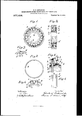
- This intention relates to a roller bearing and embraced b -aconical casing so that the rolls Ina-y e cieiitly sustain end thrust, and the objectof the invention is to .hold the rolls elastically in place upon-the hub while permitting a slight expansive movement of the rolls thereon.
- This object is attained by forming each rollwith a shallow groove upon its periphery about the middle of its length, and fitting to the-serieso'f rolls an elastic band of greater width than thickness, which embraces the rolls at the several grooves, so as to prevent; any material ex pansive movement of the rolls.
- Each roll e is formed-with a peripheral groove of greater width than depth having a Hatedge f and afhereled edge 7', and'a tension band g is fitted to the grooves and to the saidvedges-andencirclesihe huhis illustrated separately in Fight collar b at its smaller end proportioned to.
- the invention will be understood by ref- "The larger end of the hub is r abheted, forming an outwardly-facingshoulder d and a seat 4 upon-the hub.
- v A. seriesof rolls e is fitted to the hub and encircled by'a casing e all of the rolls, so as to-retainthem-u on.
- the hub in contact Wit-lithe shoji'ilderscl-v he tension band as shown in Fig,- 3 isfa continw point and it is thereforehensi-blefl t s great Strain pplied internally, Th
- the cage thus guidin the rolls in their proper-path upon the-bu Lugs l are Thu r'ed hyriyets tofu flang'Ja, which fits movably upon the seat d again-st theshoulder'd, l
- the tension band operates when the rolls have been slipped over the collar to draw them into' their, normal position upon the hub ⁇ i'itlrthe'ir smaller-ends in cont In Fig. 6, two of the rolls-are shown and the tension band Stretched straight between the rolls, althoughthe-bandis normally ofequal curvature at all points, as. shown in Fig. 3.
- Such flattening of the curvature between the several rolls is resisted elastically by the metal of the band, Which is madeof greater vldth than thickness so as to be flexed'm some degree between the rolls when snflicient force is applied.
- Such flexure of the band is not in practice so great as that shown in Fi- 6, 'where the-band-is represented tangential to the rolls merely to illustrate the nature of the fiexure and D not its extent.
- the construction of the band is not in practice so great as that shown in Fi- 6, 'where the-band-is represented tangential to the rolls merely to illustrate the nature of the
- the split in the mug permits it be readily expanded for slipping over a series of rolls after they are assembled upon the hub, which as i'iotpossihle with an unact with s'i'msa' asides. ring, such is" teen-ted, ante efinitely limit the present construction to d outward expansion of; the rolls.
- the present construction is especially adapted to what is termed ahigh-duty bearing in which a heavy load m'ust be sustained by relatively short rolls, for want;
Landscapes
- Engineering & Computer Science (AREA)
- General Engineering & Computer Science (AREA)
- Mechanical Engineering (AREA)
- Rolls And Other Rotary Bodies (AREA)
Description
(I. S. LOCKWOOD. ROLLER BEARING HAVING GROOVBD ROLLS AND TENSION BAND.
APPLIGATIOH FILED JUNE 2, 1910. 977,458. Patented Dec.6,1910.
% wmnmfor mm: runs. an: mm. mum-rm n. c.
UNITED STATES PATENT OFFICE.
CHARLES S. LOCKWOOD, F NEWARK, NEW JERSEY, ASSIGNOR TO HYATT ROLLER BEARING COMPANY, OF HARRISON, NEW J EItSEY, A CORPORATION OF NEW JERSEY.
BOLLEB BEARING HAVING GROQVEI) ROLLS AND TENSION-BAND. m
Specification of Letters Patent.
Application filed'June 2, 1910. Serial No. 564,540.
- 1 '0 all whom it may concern:
having tapering rolls fitted to a conical huh Be-it known that 1,- CHARLES S. Loon woon, a citizen of the United States, residing at 289 Market street, Newark, countypf Essex, and State of New Jersey, have 111 vented certain new and useful Improvements in Roller-Bearings Having Grooved Rolls and Tension-Bands, fully described and represented in the following spec fication and the accompanying dra wi.ngs,- forming a part of the same.
This intentionrelates to a roller bearing and embraced b -aconical casing so that the rolls Ina-y e cieiitly sustain end thrust, and the objectof the invention is to .hold the rolls elastically in place upon-the hub while permitting a slight expansive movement of the rolls thereon. This object is attained by forming each rollwith a shallow groove upon its periphery about the middle of its length, and fitting to the-serieso'f rolls an elastic band of greater width than thickness, which embraces the rolls at the several grooves, so as to prevent; any material ex pansive movement of the rolls.
, The tension hand IS 'SO proportioned that any end movement of the rolls tends to are'keptin asuit-able path upon the hub to straighten the curvature of the bandbetween the-peripheries of adjacent rolls, which permits a slightelastlc movement of the rolls when subjected to sufiicient strain-.- The rolls retain the tensionha-nd in the grooves, by
an inwardly facing shoulder formed upon" a collar atthe srmi'ller end of the hub,- the smaller endsof the rolls contacting with such Shoulder in their normal movement "yields sufliciently to permit," the crowding slightly: elevated collar -'which formsfgtheshoulder. at the smaller end of 'tlhe;hub,'while jssah'o'ut the hub. The 'space between a .coni
cal hub and. conical casing is of tapering form, so that end thrust upon the'hub tends to. force the rolls upwardly upon thei'rre- :s'ective conical's'eats, andlgthe elasticity of. t e tension band-produces an elastic resist ance to suehupwardmoirement and prevents the rolls fromyielding' materially, while it' yields 'ys'ufiiciently to avoid abrupt shocks,- when the hub subjected to suddeIi'thrust.-"
The elasticity of the teiisionhand also "perform's another important tunction as it of theseries of rolls upon theihubflo'i er the embre'eedlbi' h a ercnce to the annexed drawing, in which Figure 1 is an elevation of the hearlng with the casing removed; Fig. a longi-.
a cross sectionof'one of the rolls and part of the cage at the forward edge of the tension hand.
where. it is shown with conical seata and aform a slight inwardly-facing shoulder r-.'
having a tapering seat fitted to the exterior of the rolls. Each roll e is formed-with a peripheral groove of greater width than depth having a Hatedge f and afhereled edge 7', and'a tension band g is fitted to the grooves and to the saidvedges-andencirclesihe huhis illustrated separately in Fight collar b at its smaller end proportioned to.
Patented Deere, 1910. I
The invention will be understood by ref- "The larger end of the hub is r abheted, forming an outwardly-facingshoulder d and a seat 4 upon-the hub. v A. seriesof rolls e is fitted to the hub and encircled by'a casing e all of the rolls, so as to-retainthem-u on. the hub in contact Wit-lithe shoji'ilderscl-v he tension band as shown in Fig,- 3 isfa continw point and it is thereforehensi-blefl t s great Strain pplied internally, Th
groove. as shown'in Fig; 5, W ereifthe parts" edge 9' of the tension band 'isbeve'ledliiif .wardly mam plane of-the' ed f upon the are enlarged to showthe for'ni moreclea'i'lj; A cage havinga' conical shell his; rovitled with apertures z' to receive the. r'o s e, and with a ring jat its larger end-which, after the parts are assembledupon thel h-uligis.se-
der 0, the cage thus guidin the rolls in their proper-path upon the-bu Lugs l are Thu r'ed hyriyets tofu flang'Ja, which fits movably upon the seat d again-st theshoulder'd, l
when the rolls are in contact with the shoal: Y 1
no ous ringandnot; dixided'oi' split-shiny":
Ibo"
'forme'dnp'oh the cage atithe ed es of the; apertures and projectedinward y at right 'ang lesto the cage to p'ermitthe insertion of I the rolls from. the inside, after which thellO the shoulder c.
lugs areibe'nt-to fit; the sides of "the rollsloosely, asshownrin Fig)? \v r It is obvious that the tension band cannot be-appliedto-thje rolls afterftlieya're assembled upon-the hub, and it is therefore neces;
sary to fit the "rollswithin the cage and apply the tension bandto the. grooves,- before the hub is inserted in the rolls.
In assembling the 'ca e With the rolls, the
tension band is firstp aced over the cage,'
the rolls inserted through the apertures from' the'inner side of the cage and engaged. with the tension band, and-the lugs l upon the cageare then bent to prevent the escapev of 'the rolls, thus inakingthe band, thejcage,
and the -rollsa unitary struct-ure'whiclrcan be handled without the derangement of its parts. The rolls can then'be forced-over the collar b at the smaller end of the hub; as shownin" Fig.5, the tension "band yielding, or in some measurestraightening between .the sereral rolls as indicated in Fig. (5, to
permit such expansion of'the rolls.
The tension band operates when the rolls have been slipped over the collar to draw them into' their, normal position upon the hub \i'itlrthe'ir smaller-ends in cont In Fig. 6, two of the rolls-are shown and the tension band Stretched straight between the rolls, althoughthe-bandis normally ofequal curvature at all points, as. shown in Fig. 3. Such flattening of the curvature between the several rolls is resisted elastically by the metal of the band, Which is madeof greater vldth than thickness so as to be flexed'm some degree between the rolls when snflicient force is applied. Such flexure of the band is not in practice so great as that shown in Fi- 6, 'where the-band-is represented tangential to the rolls merely to illustrate the nature of the fiexure and D not its extent. The construction of the band.
enablesitijto elastically resist. expansion of the rollswith nicreasmg resistance as the rolls move upwardly upon the hub. andforms. rigid obstacle to their movement beyond a certain limit, as the ring embraces the series of rolls positively and is not split.
or divided to permit its yielding indefinitely. Inthis respect it differs n'iaterially from rings which have. been split upon one side and applied to rolls in a manner similar to n'iy divided ring, for the mere. purpose of holdingrolls upon a hub while assembling the parts ofthe bearing.
In such a construt-non, the split in the mug permits it be readily expanded for slipping over a series of rolls after they are assembled upon the hub, which as i'iotpossihle with an unact with s'i'msa' asides. ring, such is" teen-ted, ante efinitely limit the present construction to d outward expansion of; the rolls.
It will be'observed that the tension'liand is applied to the rolls intermediate their ends so that any retarding effect which the- :ban' may have upon the rolls does not tend to. twist'the rollsout of their normal rela'-' tion to the' hub, which sometimes results when'aguiding device is applied to one end only of the rolls.
The present construction is especially adapted to what is termed ahigh-duty bearing in which a heavy load m'ust be sustained by relatively short rolls, for want;
of -space to apply a long bearing; and such short rolls have a greater tendency" than' long rolls to twist outof line within the bearing, Y By applying the tension band to the middle of the roll it has no tendency to retard one end of the roll more than the other, and thus produces"no tendency to twist the rolls out of place.
Having thus set forth-the nature of the invention what is claimed 'herein is 1. In a roller bearing, the combination, with a conical hub havin'gjan inwardly facing shoulder near its smaller end, of a series of tapering rolls fitted to such hub with their smaller ends against such shoulder and having each a shallow .groove' about the middle ofits length, and an undivided annular flexible tension band fitted to such groove and arrangedand operatedt o hold the rolls vagai'nst the said shoulder and to elastically resist certain expansive movements of the rolls upon the hub, and positively prevent the expansion-of the rolls beyond a certain limit.
2. In a roller bearing, the. combination, with a conical hub having an inwardlyfacingshoulder near its smaller end, of a series of tapering rolls fitted to such hub and having-each a groove at the middle (if its length, an annular flexible tension band of greater breadth than thickness fittedto" such grooves, and a cage having a conical shellwith apertures to admit the rolls, and
a flange upon the cage en 'aging such hub, toguide the cage and rolf ment.
In testimony whereof I have hereunto set my hand in the presence of two subscribing witnesses.
CHARLES s. LooKWoon.
\Vitnesses':
VILLIAM D. BROWN,
Ivy W. ASLIN.
s in their move-I
Priority Applications (1)
| Application Number | Priority Date | Filing Date | Title |
|---|---|---|---|
| US56454010A US977458A (en) | 1910-06-02 | 1910-06-02 | Roller-bearing having grooved rolls and tension-band. |
Applications Claiming Priority (1)
| Application Number | Priority Date | Filing Date | Title |
|---|---|---|---|
| US56454010A US977458A (en) | 1910-06-02 | 1910-06-02 | Roller-bearing having grooved rolls and tension-band. |
Publications (1)
| Publication Number | Publication Date |
|---|---|
| US977458A true US977458A (en) | 1910-12-06 |
Family
ID=3045836
Family Applications (1)
| Application Number | Title | Priority Date | Filing Date |
|---|---|---|---|
| US56454010A Expired - Lifetime US977458A (en) | 1910-06-02 | 1910-06-02 | Roller-bearing having grooved rolls and tension-band. |
Country Status (1)
| Country | Link |
|---|---|
| US (1) | US977458A (en) |
Cited By (6)
| Publication number | Priority date | Publication date | Assignee | Title |
|---|---|---|---|---|
| US3341262A (en) * | 1964-12-21 | 1967-09-12 | Scully Jones Company | Recirculating bearing |
| DE4334534A1 (en) * | 1993-10-09 | 1995-04-13 | Schaeffler Waelzlager Kg | Radial bearing |
| US6238095B1 (en) | 1999-01-06 | 2001-05-29 | The Timken Company | Relieved tapered roller bearing with true rolling contacts |
| DE102005048920A1 (en) * | 2005-10-13 | 2007-04-19 | Schaeffler Kg | Axial roller bearing e.g. for rotor bearing in wind power station, has tracks of pressure disks and are formed without outer guidance board whereby radial support of tapped roller takes place by tension ring |
| DE102005048869A1 (en) * | 2005-10-13 | 2007-04-19 | Schaeffler Kg | Radial tapered roller bearing e.g. for rotor bearing in wind power plant, has clamping ring which is guided axially through annular grooves machined in larger front sides of tapered rollers |
| DE102012217506A1 (en) * | 2012-09-27 | 2014-03-27 | Schaeffler Technologies Gmbh & Co. Kg | Bearing assembly for transmission e.g. differential gear of vehicle, has roller bearing whose retainer is connected to flanged wheel in form-fitting manner, such that rolling bearing side faces of rolling element are assigned |
-
1910
- 1910-06-02 US US56454010A patent/US977458A/en not_active Expired - Lifetime
Cited By (7)
| Publication number | Priority date | Publication date | Assignee | Title |
|---|---|---|---|---|
| US3341262A (en) * | 1964-12-21 | 1967-09-12 | Scully Jones Company | Recirculating bearing |
| DE4334534A1 (en) * | 1993-10-09 | 1995-04-13 | Schaeffler Waelzlager Kg | Radial bearing |
| US6238095B1 (en) | 1999-01-06 | 2001-05-29 | The Timken Company | Relieved tapered roller bearing with true rolling contacts |
| DE102005048920A1 (en) * | 2005-10-13 | 2007-04-19 | Schaeffler Kg | Axial roller bearing e.g. for rotor bearing in wind power station, has tracks of pressure disks and are formed without outer guidance board whereby radial support of tapped roller takes place by tension ring |
| DE102005048869A1 (en) * | 2005-10-13 | 2007-04-19 | Schaeffler Kg | Radial tapered roller bearing e.g. for rotor bearing in wind power plant, has clamping ring which is guided axially through annular grooves machined in larger front sides of tapered rollers |
| DE102012217506A1 (en) * | 2012-09-27 | 2014-03-27 | Schaeffler Technologies Gmbh & Co. Kg | Bearing assembly for transmission e.g. differential gear of vehicle, has roller bearing whose retainer is connected to flanged wheel in form-fitting manner, such that rolling bearing side faces of rolling element are assigned |
| DE102012217506B4 (en) * | 2012-09-27 | 2014-07-10 | Schaeffler Technologies Gmbh & Co. Kg | Bearing arrangement for a transmission |
Similar Documents
| Publication | Publication Date | Title |
|---|---|---|
| US2504776A (en) | Supporting structure | |
| US1746978A (en) | Adapter for bearings | |
| US1811679A (en) | Ball and roller bearing | |
| US977458A (en) | Roller-bearing having grooved rolls and tension-band. | |
| US1970449A (en) | Antifriction bearing | |
| US3174813A (en) | Universal joint seal | |
| US1370599A (en) | Resilient support for machinery | |
| US3506317A (en) | Antifriction bearing | |
| US1469991A (en) | Means for preventing displacement of rollers-in | |
| US1773427A (en) | Shaft bearing | |
| US2818313A (en) | Roller bearing | |
| US3526409A (en) | Sealing device | |
| EP2975278B1 (en) | Rolling bearing and method for manufacturing such a rolling bearing | |
| US2105013A (en) | Roller bearing cage | |
| US2648557A (en) | Spring retainer ring | |
| US1844552A (en) | Self-aligning bearing | |
| US1332444A (en) | Ball-bearing | |
| US2033074A (en) | Antifriction bearing | |
| US1593580A (en) | Roller bearing | |
| US1324523A (en) | Flexible coupling fob | |
| US1865566A (en) | Piston packing | |
| US1300386A (en) | Roller-bearing. | |
| US1105132A (en) | Antifriction-bearing. | |
| US3049355A (en) | Seals for bearings | |
| US2628687A (en) | Spring loaded preloading mechanism for blade retention with increased stiffness |