US9769775B2 - Sync interval determination - Google Patents
Sync interval determination Download PDFInfo
- Publication number
- US9769775B2 US9769775B2 US14/353,324 US201114353324A US9769775B2 US 9769775 B2 US9769775 B2 US 9769775B2 US 201114353324 A US201114353324 A US 201114353324A US 9769775 B2 US9769775 B2 US 9769775B2
- Authority
- US
- United States
- Prior art keywords
- time
- synchronization signal
- time offset
- time point
- transmitting
- Prior art date
- Legal status (The legal status is an assumption and is not a legal conclusion. Google has not performed a legal analysis and makes no representation as to the accuracy of the status listed.)
- Active, expires
Links
- 238000000034 method Methods 0.000 claims abstract description 30
- 230000004044 response Effects 0.000 claims description 14
- 230000005540 biological transmission Effects 0.000 claims description 12
- 238000012935 Averaging Methods 0.000 claims description 3
- 238000004891 communication Methods 0.000 description 10
- 238000010586 diagram Methods 0.000 description 6
- 230000007246 mechanism Effects 0.000 description 4
- 230000006870 function Effects 0.000 description 3
- 230000001360 synchronised effect Effects 0.000 description 3
- 238000004364 calculation method Methods 0.000 description 2
- 230000007123 defense Effects 0.000 description 2
- 230000001419 dependent effect Effects 0.000 description 2
- 230000006399 behavior Effects 0.000 description 1
- 230000008901 benefit Effects 0.000 description 1
- 230000021615 conjugation Effects 0.000 description 1
- 238000013461 design Methods 0.000 description 1
- 238000005516 engineering process Methods 0.000 description 1
- 238000009472 formulation Methods 0.000 description 1
- 238000005259 measurement Methods 0.000 description 1
- 239000000203 mixture Substances 0.000 description 1
- 238000010295 mobile communication Methods 0.000 description 1
- 238000012545 processing Methods 0.000 description 1
- 239000002699 waste material Substances 0.000 description 1
Images


Classifications
-
- H—ELECTRICITY
- H04—ELECTRIC COMMUNICATION TECHNIQUE
- H04W—WIRELESS COMMUNICATION NETWORKS
- H04W56/00—Synchronisation arrangements
-
- H—ELECTRICITY
- H04—ELECTRIC COMMUNICATION TECHNIQUE
- H04J—MULTIPLEX COMMUNICATION
- H04J3/00—Time-division multiplex systems
- H04J3/02—Details
- H04J3/06—Synchronising arrangements
- H04J3/0635—Clock or time synchronisation in a network
- H04J3/0638—Clock or time synchronisation among nodes; Internode synchronisation
- H04J3/0658—Clock or time synchronisation among packet nodes
- H04J3/0661—Clock or time synchronisation among packet nodes using timestamps
- H04J3/0667—Bidirectional timestamps, e.g. NTP or PTP for compensation of clock drift and for compensation of propagation delays
-
- Y—GENERAL TAGGING OF NEW TECHNOLOGICAL DEVELOPMENTS; GENERAL TAGGING OF CROSS-SECTIONAL TECHNOLOGIES SPANNING OVER SEVERAL SECTIONS OF THE IPC; TECHNICAL SUBJECTS COVERED BY FORMER USPC CROSS-REFERENCE ART COLLECTIONS [XRACs] AND DIGESTS
- Y02—TECHNOLOGIES OR APPLICATIONS FOR MITIGATION OR ADAPTATION AGAINST CLIMATE CHANGE
- Y02D—CLIMATE CHANGE MITIGATION TECHNOLOGIES IN INFORMATION AND COMMUNICATION TECHNOLOGIES [ICT], I.E. INFORMATION AND COMMUNICATION TECHNOLOGIES AIMING AT THE REDUCTION OF THEIR OWN ENERGY USE
- Y02D30/00—Reducing energy consumption in communication networks
- Y02D30/70—Reducing energy consumption in communication networks in wireless communication networks
Definitions
- the invention relates to a method of synchronizing clocks of at least two devices in a network and a corresponding wireless device for synchronizing its clock with another wireless device.
- Time synchronization is a very important issue for mobile communication systems, especially for TD-SCDMA, WiMAX or LTE systems. Generally these communication systems need time accuracy within several microseconds ( ⁇ s).
- GPS Global Positioning System
- RBS Radio Base Station
- GPS system is limited by its satellite communication mechanism.
- the GPS system has difficulty in site selection, especially for in-door RBS, where the satellite signal from the GPS system is too weak to be detected.
- the GPS system is controlled by the US Department of Defense, its security and availability are under consideration for other countries and organizations.
- IEEE 1588 is proposed to synchronize real-time clocks in the nodes of a distributed system that communicate using a network. It enables precise synchronization of clocks in measurement and control systems implemented with technologies such as network communication, local computing and distributed objects.
- the clocks communicate with each other over a communication network.
- the protocol generates a master-slave relationship among the clocks in the system.
- the clock of a slave device is synchronized to the clock of its master device, and all clocks ultimately derive their time from a clock known as the grandmaster clock.
- IEEE 1588 protocol eliminates the needs of communication to a satellite system and has been extensively investigated to be used in all kinds of networks. It can be either used to replace some GPS or as a complementation when GPS is not detected. For example, for Femto-cell, synchronization by means of IEEE 1588 protocol will be more reliable than using GPS since GPS signal might be too small to be detected.
- each slave synchronizes to its master using Sync, Follow_Up, Delay_Req, and Delay_Resp messages.
- the ‘sync’ message is sent periodically (2 seconds in default) from the master device to the slave device to update the clock information at the slave device.
- the slave clock When the slave clock is accurate, the frequent transmission of sync message will waste the communication bandwidth in the network and also consume the calculation power in the slave device to perform corresponding operations. On the other hand, when the slave clock is not accurate or stable, it may result in a relatively large time offset between the master clock and the slave clock.
- a method for synchronizing a first device with at least one second device transmits a synchronization signal to said at least one second device to determine at least one time offset between a clock of the first device and at least one clock associated with said at least one second device, receives said at least one time offset from said at least one second device; and determines a time interval for the first device based on a time offset parameter corresponding to said at least one time offset, after which time interval the first device transmits a next synchronization signal to said at least one second device.
- Such a method is suitable for a radio station receiving data signals.
- the messages can be optimally scheduled and the radio station is able to reduce its power consumption when the time offset between the first device and the second device is small.
- the first device is a master device and the second device is a slave device whose clock is synchronized to the master clock of the master device.
- the frequency of transmitting the unicast synchronization messages are balanced with the time offset between the first device and the second device.
- said time offset parameter equals to an averaging value of said at least one time offset or the smallest one of said at least one time offset. The determination of the frequency of multicasting the synchronization messages has taken the behavior of all the slave devices.
- the master device further receives a request message from a first one of said at least one second device, transmits a response message to said first second device to inform a fourth time point of receiving said request message at the first device.
- the synchronization signal comprises information about a first time point of transmitting the synchronization signal at the first device.
- a first one of said at least one time offset is determined based on the first time point, the fourth time point, a second time point of receiving said synchronization signal at the first second device, and a third time point of transmitting said request message from the first second device.
- the slave device determines the time offset value and uses it to adjust its slave clock.
- a report message containing the slave time offset can be sent to the master after the time offset is determined by the slave device. This option is useful in cases where it is not possible both to achieve sufficient time stamp accuracy and place the time stamp in the message as it is transmitted.
- the master device receives a request message from a first one of said at least one second device, which includes the information about a second time point of receiving said synchronization signal at the first second device and a third time point of transmitting said request message from the first second device, and notes a fourth time point of receiving said request message at the first device. Then the master device determines a first one of said at least one time offset based on the first time point, the second time point, the third time point and the fourth time point.
- a synchronization method for synchronizing a first device with a second device comprises the steps of: transmitting a synchronization signal from a first device to a second device; transmitting a follow up message from the first device to the second device, indicating a first time point (t 1 ) of transmitting the synchronization signal; transmitting a request message from the second device to the first device; transmitting a response message from the first device to the second device to inform the fourth time point (t 4 ) of receiving said request message at said first device; determining at least one time offset between a clock of the first device and a clock associated with said second device according to the first time point (t 1 ), a second time point (t 2 ) of receiving said synchronization signal at the second device, a third time point (t 3 ) of transmitting said request message, and the fourth time point (t 4 ); receiving said at least one time offset from said second device; and determining a time interval for the first device based
- a first device for synchronizing with at least one second device.
- Said first device comprises a transmitter for transmitting a synchronization signal to said at least one second device to determine at least one time offset between a clock of the first device and at least one clock associated with said at least one second device; a receiver for receiving said at least one time offset from said at least one second device; and a time interval determination unit for determining a time interval for the first device based on a time offset parameter corresponding to said at least one time offset, after which time interval the transmitter transmits a next synchronization signal to said at least one second device.
- FIG. 1 is a timing diagram of a Delay-Request-Response mechanism according to the IEEE 1588 protocol.
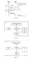
- FIG. 2 is a block diagram of a master device for sending sync messages according to an embodiment of the present invention
- FIG. 3 is a block diagram of a slave device for receiving the sync message according to an embodiment of the present invention.
- FIG. 4 is a flow chart of an exemplary method of performing the synchronization method, according to an embodiment of the present invention.
- FIG. 1 is a timing diagram of a basic Delay-Request-Response mechanism.
- Master time refers to the time according to a clock of a master device
- Slave time refers to the time according to a clock of a slave device.
- the master device After a device has been selected as the master device, for example, by using the Best Master Clock algorithm, the master device at first sends a synchronization message (Sync) to its slave at time point t 1 . Then the master device sends a follow up message after the transmission of the associated synchronization message, which includes the precise information about t 1 . Both the synchronization message and the follow up message are received by a slave device.
- Sync synchronization message
- the follow up message is optional.
- the value of t 1 is embedded in the synchronization message and there is no follow up message associated with the sync message. However in this case, it requires some sort of hardware processing for highest accuracy and precision.
- the slave device sends a request message (Delay_Req) to the master device at time point t 3 , and notes t 3 in its memory.
- the master device receives the request message and notes the time of reception t 4 .
- the master device generates a response message (Delay_Resp) corresponding to the request message.
- the value of t 4 is conveyed to the slave device.
- the slave device After the receipt of the response message from the master device, the slave device now possess information about four time points, t 1 , t 2 , t 3 and t 4 .
- the values of the time points t 1 and t 4 are measured using the time clock of the master device, and the values of the time points t 2 and t 3 are measured using the time clock of the slave device.
- These timestamps may be used by the slave device to compute the offset of the slave clock with respect to the master and the mean propagation time of messages between the two clocks.
- the slave device may adjust its clock and synchronize to the master device.
- FIG. 2 is a block diagram of a master device for sending sync messages according to an embodiment of the present invention, and the master device is designated generally as master device 200 .
- the master device 200 includes a controller 202 , a memory 204 , a clock 206 , an interval determination device 208 , a transmitter 210 and a receiver 212 .
- the controller 202 controls the communication functions of the master device 200 and coordinates all the components of the master device to work together.
- the memory 204 is used to save some necessary system information.
- the clock 206 is selected as the master clock, to which all the slave clocks synchronize to.
- the transmitter 210 is used to transmit various messages from the master device.
- the transmitter 210 transmits, among others, event messages, such as the synchronization message, the follow-up message and the response message as mentioned with reference to FIG. 1 .
- the receiver 212 is used to receive a variety of messages from the other devices, including a grandmaster device or the slave devices.
- the receiver 212 may receive, among others, some event messages such as the response message from the slave device and general messages from other devices to perform clock selection.
- the interval determination device 208 is used to determine the time interval between the transmissions of two successive synchronization messages. This interval is very important to the whole synchronization system because all the timing is centered around the synchronization interval.
- FIG. 3 is a block diagram of a slave device which may be configured to implement an embodiment of the present invention and generally designated as slave device 300 .
- the slave device 300 includes a controller 302 , a memory 304 , a clock 306 , a clock adjustment device 308 , a transmitter 310 and a receiver 312 .
- the controller 302 controls the communication functions of the slave device 300 and coordinates all the components of the slave device.
- the transmitter 310 is used to transmit various messages from the slave device 300 to the master device 200
- the receiver 312 is used to receive a variety of messages from the master devices.
- the transmitter may transmit, among others, a report message to inform the master device of the time offset value between the slave clock and the master clock.
- the time adjustment device 308 determines the time offset between the slave clock 306 and the master clock 206 , and the time delay from the master device to the slave device, and uses the time offset to adjust the clock 306 so as to synchronize to the master clock.
- the master clock can be selected by using for example the Best master clock algorithm.
- the algorithm determines which of the clocks described in several Announce messages is the best clock. In determination of the best clock, the algorithm may take into consideration the priority, the accuracy, the stability and the traceability.
- the transmitter 210 broadcasts a synchronization message at time point t 1 to inform all the other devices in the network.
- the synchronization message may include an estimate of the sending time of the sending time t 1 .
- the transmitter 210 is also configured to transmit a corresponding follow up message after the transmission of the synchronization message to inform the slave device of the precise value of sending the synchronization message, t 1 .
- the synchronization message and the follow up message are received by the slave device 300 through its receiver 312 .
- the slave controller notes the receipt time point t 2 of the synchronization message and derives the value of time point t 1 from the follow up message.
- the slave device 300 sends a request message to the master device 200 through the slave transmitter 310 at time point t 3 , in response to the receipt of the synchronization message.
- the master receiver 212 receives the request message (Delay_Req) from the slave device 300 .
- the controller 202 notes the time of reception t 4 of the request message and includes the value of t 4 into a response message (Delay_Resp), which is also transmitted by the transmitter 210 to the slave device 300 .
- the time adjustment device 308 may determines the time offset and the time delay according to F 3 and 4 , and adjusts the slave clock 306 based on the time offset thus determined, so as to synchronize to the master clock 206 .
- the time offset is also transmitted by the slave device 300 through a report message to the master device 200 .
- the time offset is transmitted to the master device 200 as soon as it is derived.
- the receiver 212 receives the time offset message from the slave device, and sends said the time offset to the interval determination device 208 .
- the interval determination device 208 determines a time interval of the master device based on the time offset.
- the time interval determined above is used by the controller 202 to determine when to send the next synchronization message.
- the time interval is set between 0.5 s ⁇ 5 s, and the values of T refL and T refH are set to be 0.4 ⁇ s and 4 ⁇ s, respectively.
- the time offset value is greater than T refH
- the time interval is set to 0.5 s
- the time offset value is smaller than T refL
- the time interval is set to 5 s.
- the skilled person in the art may choose other values of these parameters, which also fall in the scope of the present invention.
- the messages can be optimally scheduled and the communication traffic between the master device and the slave device may be optimized by sending the next synchronization after a longer time interval when the time offset of the slave device is small.
- sending the next synchronization after a shorter time interval when the time offset of the slave device is large it ensures timely synchronization for inaccurate slave clocks.
- time interval values can be predetermined and stored in a lookup table. A corresponding entry in the lookup table can be found according to the current time offset range.
- the time interval can be determined by a moving average method.
- the master device may store all the time offset values in its memory 204 , and determines the interval based on a time offset parameter corresponding to the time offset values of the plurality of slave device.
- the time offset parameter is the average value of all the time offsets received to ensure the transmission of synchronization message is appropriate to most of the slave devices.
- the average value may be selected according to the least square method, so as to minimize the sum of the squares of the errors between the average value t para and the actual time offsets t 1 to t n
- ⁇ i 1 n ⁇ ( t para - t i ) 2 , wherein n is the number of the plurality of slave devices and t i is the time offset received from the i th slave device.
- the slave device may also transmits the values of time point t 2 and time point t 3 to the master device, for example, by including these values into a request message. Then the master device can determine the time offset between the master clock and a particular slave clock associated with said request message, and therefore determine the synchronization interval based on said time offset.
- FIG. 4 is a flow chart of an exemplary method of performing the synchronization method, according to an embodiment of the present invention.
- the method starts with transmitting a synchronization signal to at least one slave device.
- the slave device may synchronize to the master clock by the message flow as described with reference to FIG. 1 .
- the time offset between the slave clock and the master clock is derived.
- the master device 200 receives the time offset from the slave device 300 . Said time offset can be conveyed by a report message.
- the master device 200 calculates a time interval based on the time offset.
- the time interval is the time period between the transmission of the previous synchronization signal and the transmission of the next synchronization signal.
- the calculation of the time interval can be conducted as described above.
- the single time offset from said slave device is sufficient to determine the timer interval between two successive sync messages.
- the first sync message is multicast to a plurality of slave devices and received by more than one slave devices. Then the master device will receive more than one time offsets. In this case, the master device may use the average value of these time offsets in responsive to the first sync message to calculate the time interval. Alternatively the master device may also use the smallest one of these time offsets to calculate the time interval.
- the master device sends the next synchronization message to the slave device(s) after the time interval has expired since the transmission of the previous synchronization message.
Landscapes
- Engineering & Computer Science (AREA)
- Computer Networks & Wireless Communication (AREA)
- Signal Processing (AREA)
- Synchronisation In Digital Transmission Systems (AREA)
Abstract
Description
T −MS=offset+MS delay=t2−t1. (1)
T −SM=−offset+SM delay=t4−t3. (2)
Offset=(Slave time)−(Master time)=[(t 2 −t 1)−(t 4 −t 3)]/2 (3)
Delay=[(t 2 −t 1)+(t 4 −t 3)]/2 (4)
T syncinterval =T syncint0*(t ref /t para) if trefL≦tpara≦t refH (5)
wherein Tsyncint0=2 s is a default time interval of the master device; tref is a reference time offset of 1 μs; tpara is a time offset parameter, which is the time offset value received in this embodiment; TrefL and TrefH are the lower and upper limits of the time offset parameter respectively.
wherein n is the number of the plurality of slave devices and ti is the time offset received from the ith slave device.
Claims (20)
T syncinterval =T syncint0*(t ref /t para) if t refL≦tpara≦t refH
T offset _ 1=[(t2−t1)−(t4−t3)]/2.
T syncinterval=T syncint0*(t ref/t para) if t refL≦tpara≦t refH
T offset _ 1=[(t2−t1)−(t4−t3)]/2.
Applications Claiming Priority (1)
| Application Number | Priority Date | Filing Date | Title |
|---|---|---|---|
| PCT/CN2011/001886 WO2013067655A1 (en) | 2011-11-11 | 2011-11-11 | Sync interval determination |
Publications (2)
| Publication Number | Publication Date |
|---|---|
| US20140269673A1 US20140269673A1 (en) | 2014-09-18 |
| US9769775B2 true US9769775B2 (en) | 2017-09-19 |
Family
ID=48288422
Family Applications (1)
| Application Number | Title | Priority Date | Filing Date |
|---|---|---|---|
| US14/353,324 Active 2032-06-01 US9769775B2 (en) | 2011-11-11 | 2011-11-11 | Sync interval determination |
Country Status (4)
| Country | Link |
|---|---|
| US (1) | US9769775B2 (en) |
| EP (1) | EP2777183B1 (en) |
| CN (1) | CN103999387B (en) |
| WO (1) | WO2013067655A1 (en) |
Families Citing this family (11)
| Publication number | Priority date | Publication date | Assignee | Title |
|---|---|---|---|---|
| CN103001720B (en) * | 2012-11-12 | 2017-05-10 | 中兴通讯股份有限公司 | Time synchronization method and device |
| US9973601B2 (en) * | 2013-03-15 | 2018-05-15 | Avago Technologies General Ip (Singapore) Pte. Ltd. | Fault tolerant clock network |
| JP2015039131A (en) * | 2013-08-19 | 2015-02-26 | 株式会社東芝 | Measuring apparatus and method |
| CN103596261B (en) * | 2013-11-05 | 2017-11-07 | 迈锐数据(北京)有限公司 | A kind of clock synchronizing method of vehicle detecting system |
| US10958965B2 (en) * | 2014-10-31 | 2021-03-23 | Telefonaktiebolaget Lm Ericsson (Publ) | Video stream synchronization |
| CN109005019B (en) | 2014-12-31 | 2020-01-03 | 华为技术有限公司 | Signal sending and detecting device, system and method |
| US9992258B2 (en) * | 2015-01-13 | 2018-06-05 | Whatsapp Inc. | Techniques for managing a remote web client from an application on a mobile device |
| CN104811988B (en) * | 2015-04-24 | 2019-02-22 | 迈锐数据(北京)有限公司 | A kind of quick method of network entry of wireless sensor network node |
| CN106774634A (en) * | 2016-12-08 | 2017-05-31 | 郑州云海信息技术有限公司 | A kind of skewed clock bearing calibration, device and system |
| CN110324889B (en) * | 2018-03-30 | 2021-02-09 | 华为技术有限公司 | Clock synchronization method, communication device, and communication equipment |
| WO2020213190A1 (en) * | 2019-04-19 | 2020-10-22 | 三菱電機株式会社 | Communication system, master device, slave device, and submaster device |
Citations (6)
| Publication number | Priority date | Publication date | Assignee | Title |
|---|---|---|---|---|
| CN1852049A (en) | 2005-12-30 | 2006-10-25 | 华为技术有限公司 | Method and system for realizing empty pont synchronous emitting data |
| CN101043277A (en) | 2007-04-29 | 2007-09-26 | Ut斯达康通讯有限公司 | Pulse synchronized method and module in receptivity test of mobile communication terminal |
| CN101252429A (en) | 2008-02-22 | 2008-08-27 | 浙江大学 | A Method of Improving Clock Synchronization Accuracy in Distributed Network System |
| US20090168808A1 (en) * | 2007-04-04 | 2009-07-02 | Jae-Hun Cho | Apparatus and method for performing time synchronization using gps information in communication system |
| US20100098111A1 (en) | 2008-10-21 | 2010-04-22 | Huawei Technologies Co., Ltd. | Method and system for precise-clock synchronization, and device for precise-clock frequency/time synchronization |
| US20110013737A1 (en) | 2009-07-20 | 2011-01-20 | Electronics And Telecommunications Research Institute | Time synchronization apparatus based on parallel processing |
Family Cites Families (1)
| Publication number | Priority date | Publication date | Assignee | Title |
|---|---|---|---|---|
| US6837827B1 (en) | 2003-06-17 | 2005-01-04 | Garmin Ltd. | Personal training device using GPS data |
-
2011
- 2011-11-11 WO PCT/CN2011/001886 patent/WO2013067655A1/en not_active Ceased
- 2011-11-11 US US14/353,324 patent/US9769775B2/en active Active
- 2011-11-11 CN CN201180074768.8A patent/CN103999387B/en active Active
- 2011-11-11 EP EP11875461.3A patent/EP2777183B1/en active Active
Patent Citations (6)
| Publication number | Priority date | Publication date | Assignee | Title |
|---|---|---|---|---|
| CN1852049A (en) | 2005-12-30 | 2006-10-25 | 华为技术有限公司 | Method and system for realizing empty pont synchronous emitting data |
| US20090168808A1 (en) * | 2007-04-04 | 2009-07-02 | Jae-Hun Cho | Apparatus and method for performing time synchronization using gps information in communication system |
| CN101043277A (en) | 2007-04-29 | 2007-09-26 | Ut斯达康通讯有限公司 | Pulse synchronized method and module in receptivity test of mobile communication terminal |
| CN101252429A (en) | 2008-02-22 | 2008-08-27 | 浙江大学 | A Method of Improving Clock Synchronization Accuracy in Distributed Network System |
| US20100098111A1 (en) | 2008-10-21 | 2010-04-22 | Huawei Technologies Co., Ltd. | Method and system for precise-clock synchronization, and device for precise-clock frequency/time synchronization |
| US20110013737A1 (en) | 2009-07-20 | 2011-01-20 | Electronics And Telecommunications Research Institute | Time synchronization apparatus based on parallel processing |
Non-Patent Citations (7)
| Title |
|---|
| "Overview and Timing Performance of IEEE 802.1AS" by Michael D. Johas Teener and Geoffrey M. Garner, Sep. 22-26, 2008. |
| Extended European Search Report issued by the EPO for Application No./Patent No. 11875461.3-1851 / 2777183 PCT/CN2011001886, Jun. 10, 2015. |
| IEEE Standard for a Precision Clock Synchronization Protocol for Networked Measurement and Control Systems (IEEE Instrumentation and Measurement Society); IEEE Std 1588 Jul. 24, 2008. |
| Intl. Appln. 201180074768.8, Chinese Office Action (with translation) with Search Report, dated Aug. 31, 2016. |
| PCT Chapter II Demand and Response to ISR/WO for International Application No. PCT/CN2011/001886, Aug. 28, 2013. |
| PCT International Search Report for International Application No. PCT/CN2011/001886, Aug. 23, 2012. |
| PCT Notification of Transmittal of International Preliminary Report on Patentability for International Application No. PCT/CN2011/001886, Jan. 29, 2014. |
Also Published As
| Publication number | Publication date |
|---|---|
| EP2777183A1 (en) | 2014-09-17 |
| EP2777183A4 (en) | 2015-07-08 |
| WO2013067655A1 (en) | 2013-05-16 |
| CN103999387A (en) | 2014-08-20 |
| US20140269673A1 (en) | 2014-09-18 |
| EP2777183B1 (en) | 2016-08-10 |
| CN103999387B (en) | 2017-05-17 |
Similar Documents
| Publication | Publication Date | Title |
|---|---|---|
| US9769775B2 (en) | Sync interval determination | |
| Hasan et al. | GNSS time synchronization in vehicular ad-hoc networks: Benefits and feasibility | |
| Hasan et al. | Time synchronization in vehicular ad-hoc networks: A survey on theory and practice | |
| KR101650862B1 (en) | Method and apparatus for synchronizing a wireless network with an external timing source | |
| EP2375834B1 (en) | Maintaining time of day synchronization | |
| KR100913800B1 (en) | Third generation partnership project radio network controller | |
| JP2011244486A (en) | Base station synchronization for wireless communication systems | |
| US7719994B2 (en) | Sub-frame synchronized ranging | |
| JP6132734B2 (en) | Time synchronization system and apparatus | |
| US20170214479A1 (en) | Method for transmitting time synchronization messages in a communication network, network component, and communication network | |
| US20220039042A1 (en) | Methods, second node and apparatus for determining clock asynchronization | |
| EP4286881A1 (en) | Positioning method and system for compensation of internal propagation delays | |
| EP2710761B1 (en) | Clustering apparatus and method for controlling timing | |
| GB0723098D0 (en) | Oscillator calibration | |
| CN106572528B (en) | Clock synchronization method and device | |
| US7688747B2 (en) | Sub-frame synchronized residual ranging | |
| WO2023072402A1 (en) | Apparatuses and methods relating to updating an internal clock of a mobile device | |
| Harada et al. | 20-µs accuracy time-synchronization method using bluetooth low energy for internet-of-things sensors | |
| Bush | Low-energy sensor network time synchronization as an emergent property | |
| US20160227494A1 (en) | Method and apparatus to determine a transmission time of a wireless data frame | |
| Rebel et al. | A novel indoor localization scheme for autonomous nodes in ieee 802.15. 4a networks | |
| US10887856B2 (en) | Adaptive mesh synchronized time network | |
| US20260072119A1 (en) | Positioning system | |
| HK1115484A (en) | Method and apparatus for synchronizing base stations | |
| HK1114700A (en) | Method and apparatus for synchronizing base stations |
Legal Events
| Date | Code | Title | Description |
|---|---|---|---|
| AS | Assignment |
Owner name: TELEFONAKTIEBOLAGET L M ERICSSON (PUBL), SWEDEN Free format text: ASSIGNMENT OF ASSIGNORS INTEREST;ASSIGNOR:YIN, HUI;REEL/FRAME:032724/0689 Effective date: 20111205 |
|
| STCF | Information on status: patent grant |
Free format text: PATENTED CASE |
|
| MAFP | Maintenance fee payment |
Free format text: PAYMENT OF MAINTENANCE FEE, 4TH YEAR, LARGE ENTITY (ORIGINAL EVENT CODE: M1551); ENTITY STATUS OF PATENT OWNER: LARGE ENTITY Year of fee payment: 4 |
|
| MAFP | Maintenance fee payment |
Free format text: PAYMENT OF MAINTENANCE FEE, 8TH YEAR, LARGE ENTITY (ORIGINAL EVENT CODE: M1552); ENTITY STATUS OF PATENT OWNER: LARGE ENTITY Year of fee payment: 8 |