US9769475B2 - Enhanced reference region utilization for scalable video coding - Google Patents
Enhanced reference region utilization for scalable video coding Download PDFInfo
- Publication number
- US9769475B2 US9769475B2 US13/997,935 US201213997935A US9769475B2 US 9769475 B2 US9769475 B2 US 9769475B2 US 201213997935 A US201213997935 A US 201213997935A US 9769475 B2 US9769475 B2 US 9769475B2
- Authority
- US
- United States
- Prior art keywords
- region
- regions
- layer
- reference region
- prediction
- Prior art date
- Legal status (The legal status is an assumption and is not a legal conclusion. Google has not performed a legal analysis and makes no representation as to the accuracy of the status listed.)
- Expired - Fee Related
Links
Images


Classifications
-
- H—ELECTRICITY
- H04—ELECTRIC COMMUNICATION TECHNIQUE
- H04N—PICTORIAL COMMUNICATION, e.g. TELEVISION
- H04N19/00—Methods or arrangements for coding, decoding, compressing or decompressing digital video signals
- H04N19/60—Methods or arrangements for coding, decoding, compressing or decompressing digital video signals using transform coding
- H04N19/61—Methods or arrangements for coding, decoding, compressing or decompressing digital video signals using transform coding in combination with predictive coding
- H04N19/615—Methods or arrangements for coding, decoding, compressing or decompressing digital video signals using transform coding in combination with predictive coding using motion compensated temporal filtering [MCTF]
-
- H04N19/00793—
-
- H—ELECTRICITY
- H04—ELECTRIC COMMUNICATION TECHNIQUE
- H04N—PICTORIAL COMMUNICATION, e.g. TELEVISION
- H04N19/00—Methods or arrangements for coding, decoding, compressing or decompressing digital video signals
- H04N19/10—Methods or arrangements for coding, decoding, compressing or decompressing digital video signals using adaptive coding
- H04N19/102—Methods or arrangements for coding, decoding, compressing or decompressing digital video signals using adaptive coding characterised by the element, parameter or selection affected or controlled by the adaptive coding
- H04N19/103—Selection of coding mode or of prediction mode
- H04N19/105—Selection of the reference unit for prediction within a chosen coding or prediction mode, e.g. adaptive choice of position and number of pixels used for prediction
-
- H—ELECTRICITY
- H04—ELECTRIC COMMUNICATION TECHNIQUE
- H04N—PICTORIAL COMMUNICATION, e.g. TELEVISION
- H04N19/00—Methods or arrangements for coding, decoding, compressing or decompressing digital video signals
- H04N19/10—Methods or arrangements for coding, decoding, compressing or decompressing digital video signals using adaptive coding
- H04N19/134—Methods or arrangements for coding, decoding, compressing or decompressing digital video signals using adaptive coding characterised by the element, parameter or criterion affecting or controlling the adaptive coding
- H04N19/136—Incoming video signal characteristics or properties
- H04N19/137—Motion inside a coding unit, e.g. average field, frame or block difference
- H04N19/139—Analysis of motion vectors, e.g. their magnitude, direction, variance or reliability
-
- H—ELECTRICITY
- H04—ELECTRIC COMMUNICATION TECHNIQUE
- H04N—PICTORIAL COMMUNICATION, e.g. TELEVISION
- H04N19/00—Methods or arrangements for coding, decoding, compressing or decompressing digital video signals
- H04N19/10—Methods or arrangements for coding, decoding, compressing or decompressing digital video signals using adaptive coding
- H04N19/134—Methods or arrangements for coding, decoding, compressing or decompressing digital video signals using adaptive coding characterised by the element, parameter or criterion affecting or controlling the adaptive coding
- H04N19/146—Data rate or code amount at the encoder output
- H04N19/147—Data rate or code amount at the encoder output according to rate distortion criteria
-
- H—ELECTRICITY
- H04—ELECTRIC COMMUNICATION TECHNIQUE
- H04N—PICTORIAL COMMUNICATION, e.g. TELEVISION
- H04N19/00—Methods or arrangements for coding, decoding, compressing or decompressing digital video signals
- H04N19/10—Methods or arrangements for coding, decoding, compressing or decompressing digital video signals using adaptive coding
- H04N19/169—Methods or arrangements for coding, decoding, compressing or decompressing digital video signals using adaptive coding characterised by the coding unit, i.e. the structural portion or semantic portion of the video signal being the object or the subject of the adaptive coding
- H04N19/17—Methods or arrangements for coding, decoding, compressing or decompressing digital video signals using adaptive coding characterised by the coding unit, i.e. the structural portion or semantic portion of the video signal being the object or the subject of the adaptive coding the unit being an image region, e.g. an object
- H04N19/176—Methods or arrangements for coding, decoding, compressing or decompressing digital video signals using adaptive coding characterised by the coding unit, i.e. the structural portion or semantic portion of the video signal being the object or the subject of the adaptive coding the unit being an image region, e.g. an object the region being a block, e.g. a macroblock
-
- H—ELECTRICITY
- H04—ELECTRIC COMMUNICATION TECHNIQUE
- H04N—PICTORIAL COMMUNICATION, e.g. TELEVISION
- H04N19/00—Methods or arrangements for coding, decoding, compressing or decompressing digital video signals
- H04N19/30—Methods or arrangements for coding, decoding, compressing or decompressing digital video signals using hierarchical techniques, e.g. scalability
-
- H—ELECTRICITY
- H04—ELECTRIC COMMUNICATION TECHNIQUE
- H04N—PICTORIAL COMMUNICATION, e.g. TELEVISION
- H04N19/00—Methods or arrangements for coding, decoding, compressing or decompressing digital video signals
- H04N19/60—Methods or arrangements for coding, decoding, compressing or decompressing digital video signals using transform coding
- H04N19/61—Methods or arrangements for coding, decoding, compressing or decompressing digital video signals using transform coding in combination with predictive coding
- H04N19/619—Methods or arrangements for coding, decoding, compressing or decompressing digital video signals using transform coding in combination with predictive coding the transform being operated outside the prediction loop
-
- H—ELECTRICITY
- H04—ELECTRIC COMMUNICATION TECHNIQUE
- H04N—PICTORIAL COMMUNICATION, e.g. TELEVISION
- H04N19/00—Methods or arrangements for coding, decoding, compressing or decompressing digital video signals
- H04N19/70—Methods or arrangements for coding, decoding, compressing or decompressing digital video signals characterised by syntax aspects related to video coding, e.g. related to compression standards
Definitions
- High Efficient Video Coding is an evolving video compression standard that is under development by the Joint Collaborative Team on Video Coding (JCT-VC) formed by ISO/IEC Moving Picture Experts Group (MPEG) and ITU-T Video Coding Experts Group (VCEG).
- JCT-VC Joint Collaborative Team on Video Coding
- MPEG Moving Picture Experts Group
- VCEG ITU-T Video Coding Experts Group
- JCT-VC is planning to add a Scalable Video Coding (SVC) extension into the HEVC standard.
- SVC Scalable Video Coding
- FIG. 1 shows an example system that generates one base layer and two enhancement layers.
- FIG. 2A shows a position of co-located lower layer block.
- FIG. 2B depicts an example of use of an inter-layer reference block that may not be co-located in a different layer.
- FIG. 3 shows an example in which multiple reference blocks can be searched and potentially used to code a current coding block.
- FIG. 4 depicts an example process used by an encoder to encode a block.
- FIG. 5 depicts an example process used by a decoder to decode a block based on one or more candidate reference blocks.
- FIG. 6 depicts an example manner to transport reference block indices and shift vectors to a decoder.
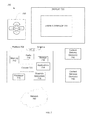
- FIG. 7 illustrates an embodiment of a system.
- FIG. 8 shows a device
- HEVC For encoding video, HEVC defines Coding Units (CUs), which are used to sub-partition a picture into rectangular blocks having variable size. Within each CU, a quad-tree based splitting scheme can be used to specify the CU partition pattern. In addition, HEVC defines Prediction Units (PUs) and Transform Units (TUs) to specify how to divide a CU for prediction and transform, respectively. After intra or inter prediction, a transform is applied to the residual blocks to generate coefficients. Next, coefficients are quantized, scanned into one-dimensional order, and context-adaptive binary arithmetic coding (CABAC) coded.
- CABAC context-adaptive binary arithmetic coding
- An SVC bit stream contains several decodable subset bit streams.
- the subset bit streams represent source video content with different resolution, frame rate, quality, bit depth, and so forth. Scalability can be achieved by using a multi-layer coding structure.
- BL Base Layer
- ELs Enhancement Layers
- FIG. 1 shows an example system that generates one BL and two ELs.
- the BL can be coded according to HEVC.
- an EL has a layer identifier equal to N, all the layers with layer identifier less than N are available.
- Blocks belonging to an EL can be predicted using Inter-Layer Reference Blocks (ILRBs) which are from lower layer pictures or by Temporal Reference Blocks (TRBs) which are from previously coded pictures in the same layer.
- ILRBs Inter-Layer Reference Blocks
- TRBs Temporal Reference Blocks
- the term “block” can be interchangeable with “region.”
- a “block” can be any shaped pixel region, such as square, rectangle, triangle, circle, and so forth.
- each of the encoders and the decoder can include a controller that initiates operations of each element, including but not limited to the transmission of the output bit stream by a radio or network interface.
- a co-located block of a lower layer is marked to be used as an inter-layer reference block (ILRB).
- ILRB inter-layer reference block
- Co-located means that a region covers the same coordinates in a base layer and an enhancement layer. For example, FIG. 2A shows that the position of co-located lower layer block is exactly aligned to the current coding block a higher layer.
- Rate-distortion cost can be a measure of amount of distortion (loss of video quality) against the amount of data required to encode the video.
- Various techniques are available for measuring rate-distortion cost.
- FIG. 2B depicts an example of use of an inter-layer reference block that may not be co-located in a different layer.
- a two dimensional offset parameter, shift_vector can be used to specify an upper left corner pixel coordinate of an ILRB relative to a block in the same layer as the ILRB that is co-located with respect to the current coding block. For example, if shift_vector has parameters (Hor, Ver), then the co-located position is the original point and with the shift_vector equal to (0, 0). If Hor is positive value, ILRB is below the co-located position. If Hor is a negative value, ILRB is above the co-located position.
- ILRB is on the right of the co-located position but if Ver is a negative value, ILRB is on the left of the co-located position.
- Other conventions can be used to identify an upper left pixel coordinate location of an ILRB.
- Various embodiments provide a manner to identify one or more candidate reference blocks used to generate a prediction block to encode a current coding block.
- the candidate reference blocks can be in the same layer as the current coding block or a different layer.
- the candidate reference blocks do not have to be co-located with the current coding block.
- Motion vectors and shift vectors can be used to identify the candidate reference blocks.
- uniform and non-uniform weighting can be applied to the candidate reference blocks to generate the prediction block. Accordingly, an encoder can determine and identify reference blocks to a decoder that can provide desirable rate-distortion cost. Accordingly, quality of video can be improved while maintaining a same bandwidth used to transmit the video.
- Various embodiments provide for use of multiple reference blocks to encode a block.
- four kinds of reference blocks are available for use in coding the current coding block.
- other numbers of reference blocks can be used. For example:
- FIG. 3 shows an example in which multiple reference blocks can be searched and potentially used to code a current coding block.
- Picture A has two temporal reference pictures: (1) forward reference picture B whose temporal id is equal to t ⁇ 1 and (2) backward reference picture C whose temporal id is equal to t+1.
- picture D is the corresponding picture of picture A.
- Picture D has the same temporal id with picture A.
- Pictures E and F are respective temporal forward and backward reference pictures of picture D.
- the temporal ids of pictures E and F are t ⁇ 1 and t+1, respectively.
- picture G is the corresponding of picture A.
- a multiple reference block list of reference blocks b to i can be generated.
- the following is an example of a reference block list.
- the reference block list building process could be adaptive or fixed. Reference blocks can be selected that have the lowest sum of absolute difference (SAD) relative to the current coding block. In an adaptive implementation, reference blocks can be selected and ordered based on their relative SAD values from lowest to highest.
- SAD sum of absolute difference
- a reference block list is set up so that all the ILRBs are added to the list with their layer distances in increasing order.
- all the TRBs can be added into the tail of the list, with their temporal distances in increasing order.
- all the T ⁇ ILRBs can be added into the tail of the list, with their layer distances in increasing order.
- all the IL ⁇ TRBs can be added into the tail of the list, with their temporal distances in increasing order.
- not all identified reference blocks are used to encode a block of interest.
- the encoder can select one or more reference blocks to use from the reference block list. For example, rate-distortion (RD) cost can be used to select the reference blocks that result in the lowest RD cost.
- RD cost can be used to select reference blocks.
- RD cost based approach to select one or more reference blocks one example implementation is to find a single best reference block.
- the encoder can build a list of reference blocks and each reference block is marked by an index.
- Another example implementation identifies multiple reference blocks for use to code a block of interest. Multiple reference blocks could be searched to identify M blocks.
- the indices of the best reference blocks can be provided by the encoder for transmission to the decoder.
- the decoder can use the reference blocks identified for use to decode a block.
- a non-RD based approach to identify reference blocks for use to code a block can be as follows.
- the order of reference blocks can be fixed and use of the first N available blocks could be identified as the reference blocks.
- the temporal and layer distance can be used as the metric for ordering.
- the weighting factors can also be fixed. For example, the largest weighting factor is given to the first reference block, the second largest weighting factor is given to the second reference block, and so on.
- a first reference block can be that which has lowest temporal and lowest layer distance from the block of interest and so forth.
- a syntax called best_reference_block_idx can signal the index in the bitstream.
- the general coding unit syntax of sections 7.3.9.1 or 7.3.10 of High Efficiency Video Coding (HEVC) Text Specification draft 8 (2012) from JCT-VC can be used to transmit best_reference_block_idx.
- HEVC High Efficiency Video Coding
- a reference block list is reconstructed.
- the decoder can construct the list.
- the decoder can construct the list in a similar manner as the encoder constructed the list.
- the decoder selects the best reference block according to best_reference_block_idx to finish the decoding process. In some cases, the decoder selects from among the best reference blocks. In some cases, several reference blocks having the lowest RD cost can be identified to the decoder. If there is no received best_reference_block_idx, decoder can use all the available reference blocks.
- a parameter max_active_reference_block_num having value N can be formed by or at instruction of the encoder to inform a decoder to use the first N available reference blocks, instead of all the reference blocks.
- the parameter max_active_reference_block_num can be transmitted to a decoder using Sequence Parameter Set (SPS), Picture Parameter Set (PPS), or slice header. Using fewer than all available reference blocks can benefit the decoder by using less buffer size.
- SPS is described for example in section 7.3.2.2 in High Efficiency Video Coding (HEVC) Text Specification draft 8 (2012) and PPS is described in section 7.3.2.3 in High Efficiency Video Coding (HEVC) Text Specification draft 8 (2012). Syntaxes controlling the whole video or whole picture can be transmitted in SPS and PPS.
- All pixel sample values in the reference blocks are multiplied by weighting factors. Specifically, luma and chroma values are multiplied by weighting factors.
- the weighting factors w 0 to w N control the magnitude of each reference block as well as the offset factor o.
- default weighting factors and offset factor are used.
- the weighting factors and offset factor are generated by an encoder and sent to a decoder.
- the weighting factor can be determined in different ways, for example:
- the offset factor o can be used to tune the weighted prediction result for flexibility.
- the offset factor can be determined by the encoder. If the encoder detects the weighted prediction result is always smaller than original pixel value, a positive offset factor can be used and vice versa.
- Motion vectors and shift vectors identify positions of the reference blocks ref 0 to ref N that are used to encode the prediction block, pred. Motion vectors and shift vectors can be provided by the encoder for transmission to the decoder.
- the shift_vector can be signaled at a block level, which means each CU/PU/TU may have a different shift_vector.
- the shift_vector can be signaled at slice/picture/layer level, which means all blocks belonging to the slice/picture/layer may use the same regional shift vector.
- most of the shift vectors are centralized to some value. This centralized value can be chosen as the regional shift vector. Coding the centralized shift vector at the slice level might benefit most of blocks in the slice.
- Use of a slice/picture/layer regional shift vector can avoid use of bits that would have been used to code the shift vectors for each block.
- a regional shift vector means the same shift vector is used to decode blocks or regions in the slice/picture/layer level. In some implementations, all blocks in the same slice/picture/layer use the regional shift vector to find their ILRBs.
- each block can also transmit a delta shift vector and the actual shift vector used to locate an ILRB can be obtained by summing the regional shift vector with the delta shift vector.
- an error difference between the block a and the prediction block pred is a residual.
- the residual will be transformed, quantized, and entroy coded into a bitstream and provided for transmission to a decoder.
- FIG. 4 depicts an example process used by an encoder to encode a block.
- Block 401 includes selecting one or more candidate reference blocks for use in encoding a candidate block.
- the candidate block can be any dimensions.
- the candidate block can be square, rectangular, triangular, circular, or any shape.
- candidate block can be a rectangular block having a variable size.
- the candidate block can be an HEVC CU.
- the one or more candidate reference blocks can be in the same layer or different layer than that of the candidate block.
- the one or more reference blocks may not be co-located with the candidate block in the different layer.
- a motion vector with x, y coordinates and reference picture index component can be used to identify offset of the candidate reference block from the candidate block.
- a shift vector can be used to identify a location of the candidate reference block relative to a co-located candidate block in the same layer as the candidate reference block.
- a motion vector relative to the co-located candidate block and a shift vector can be used to identify a location of the candidate reference block relative to a co-located candidate block.
- One or more reference blocks can be selected based on RD cost or distance from the candidate block.
- Block 402 includes determining weighting applied to the selected one or more candidate reference blocks. Based on the determined weighting, the candidate reference blocks may all be used to form a prediction block for the candidate block. Techniques for determining weighting factors are described earlier.
- block 402 could also include determining an offset factor. Determination of offset factor is described earlier.
- Block 403 includes providing encoding parameters for transmission to a decoder.
- the encoding parameters can include layer indices of every candidate reference block, motion vectors, shift vectors, weighting factors, and offset for the candidate reference blocks.
- a residual difference the prediction block and the candidate block can be quantized and entropy encoded and provided for transmission to the decoder.
- Transmission of the parameters can take place using a video bitstream. Syntax information in the bitstream can be used to transmit parameters.
- FIG. 5 depicts an example process used by a decoder to decode a block based on one or more candidate reference blocks.
- the block can be any pixel sized square or rectangle or other shapes.
- the block to be decoded can be an HEVC CU.
- Block 501 includes determining whether multiple reference blocks are used for a prediction block.
- the prediction block can be used to decode a block. If multiple reference blocks are used to determine a prediction block, then block 502 can follow block 501 . If multiple reference blocks are not used to determine a prediction block, then block 530 can follow block 501 .
- Each reference block can be identified using a layer index, motion vector, or a shift vector. Reference blocks can be identified by a video encoder.
- Block 502 includes generating a reference block.
- a technique for generating a reference block depends on the type of the reference block.
- a decoder can know whether reference block is ILRB, TRB, T+ILRB, or IL+TRB based on parameters received with the reference block. For example, if there is just a received motion vector but no shift vector, the decoder knows reference block is a TRB. If there is just a received shift vector but no motion vector, the decoder knows reference block is an ILRB. If a TRB has its own shift vector, then the reference block identified using the shift vector is a T+ILRB. If an ILRB has its own motion vector, then the reference block identified using the motion vector is an IL+TRB.
- Generating a TRB can include using a received motion vector to identify an upper left coordinate of the TRB relative to a location of a block to be decoded.
- Generating an ILRB can include using a received shift vector to identify an upper left coordinate of the ILRB relative to a co-located block in a lower level.
- a decoder can determine a layer level of the ILRB based on information received in the video stream.
- up-sampling can be applied to translate the ILRB to the dimensions and resolution of block to be decoded.
- Generating a T+ILRB can include (a) using a received motion vector to identify an upper left coordinate of a TRB relative to a location of a block to be decoded and (b) using a shift vector to identify an upper left coordinate of the T+ILRB relative to a co-located block of the TRB in a lower level.
- Generating an IL+TRB can include (a) using a shift vector to identify an upper left coordinate of a block in a lower level relative to a co-located block and (b) using a received motion vector to identify an upper left coordinate of the IL ⁇ TRB relative to a location of the block identified using the shift vector.
- the block in the lower layer may be up-sampled to the size of the current coding block. Up-sampling can include pixel interpolation and scaling to the resolution of the layer of the current coding block.
- the resolution of shift_vector can be integer or fractional.
- an interpolation filter is used to generate the actual ILRB.
- Various of interpolation filters can be used, including but not limit to bilinear filter, bi-cubic filter, poly-phase FIR filters, and so forth.
- Block 510 includes determining whether all reference blocks provided for use in decoding a block of interest have been identified.
- the relevant reference blocks can be identified by an encoder. Block 502 repeats until block 510 indicates all reference blocks have been generated.
- Block 520 includes generating a prediction block from one or more reference blocks.
- the prediction block can be generated from weighting of each of the one or more reference blocks. Weighting of each of the reference blocks can be different or the same. An example manner to generate the prediction block is described earlier.
- Block 530 includes applying inter or intra prediction using a single reference block to determine a prediction block for a block of interest.
- Techniques suggested with respect to HEVC as well as any variety of H.264 and MPEG can be used for inter or intra prediction of the prediction block.
- Block 540 includes applying residual decoding to the prediction block.
- the prediction block can be determined using one or more reference blocks.
- Residual values can be provided by an encoder of the video and can be received in entropy encoded format.
- Block 540 includes decoding the residual values.
- Decoding residual values can include applying entropy decoding and inverse quantization. Residual values may include pixel difference values between pixels in the original pre-encoded block of interest and pixels in a predicted block.
- Block 550 includes reconstructing a block of interest.
- Reconstructing the block of interest can include summing residual values with the prediction block on a per pixel basis.
- the resulting block of interest is a reconstructed version of an encoded block.
- FIG. 6 depicts an example manner to transport reference block indices and shift vectors to a decoder.
- the expressions and parameters shown in FIG. 6 can be used in a video stream to identify reference block index numbers and horizontal and vertical values of shift vectors for each of the reference blocks.
- the shift vectors are associated with a particular layer and can be transmitted from lowest layer to highest reference layer.
- Reference blocks can be TU, PU, CU, slice, picture, or layer level.
- HEVC High Efficiency Video Coding
- the following provides a table of parameters referenced in FIG. 6 that can be transmitted to a decoder.
- FIG. 7 illustrates an embodiment of a system 700 .
- system 700 may be a media system although system 700 is not limited to this context.
- system 700 may be incorporated into a personal computer (PC), laptop computer, ultra-laptop computer, tablet, touch pad, portable computer, handheld computer, palmtop computer, personal digital assistant (PDA), cellular telephone, combination cellular telephone/PDA, television, smart device (e.g., smart phone, smart tablet or smart television), mobile internet device (MID), messaging device, data communication device, and so forth.
- PC personal computer
- PDA personal digital assistant
- cellular telephone combination cellular telephone/PDA
- television smart device (e.g., smart phone, smart tablet or smart television), mobile internet device (MID), messaging device, data communication device, and so forth.
- smart device e.g., smart phone, smart tablet or smart television
- MID mobile internet device
- system 700 includes a platform 702 coupled to a display 720 .
- Platform 702 may receive content from a content device such as content services device(s) 730 or content delivery device(s) 740 or other similar content sources.
- a navigation controller 750 comprising one or more navigation features may be used to interact with, for example, platform 702 and/or display 720 .
- platform 702 can be communicatively to display 720 through a display interface.
- platform 702 may include any combination of a chipset 705 , processor 710 , memory 712 , storage 714 , graphics subsystem 715 , applications 716 and/or radio 718 .
- Chipset 705 may provide intercommunication among processor 710 , memory 712 , storage 714 , graphics subsystem 715 , applications 716 and/or radio 718 .
- chipset 705 may include a storage adapter (not depicted) capable of providing intercommunication with storage 714 .
- Processor 710 may be implemented as Complex Instruction Set Computer (CISC) or Reduced Instruction Set Computer (RISC) processors, x86 instruction set compatible processors, multi-core, or any other microprocessor or central processing unit (CPU).
- processor 710 may include dual-core processor(s), dual-core mobile processor(s), and so forth.
- Memory 712 may be implemented as a volatile memory device such as, but not limited to, a Random Access Memory (RAM), Dynamic Random Access Memory (DRAM), or Static RAM (SRAM).
- RAM Random Access Memory
- DRAM Dynamic Random Access Memory
- SRAM Static RAM
- Storage 714 may be implemented as a non-volatile storage device such as, but not limited to, a magnetic disk drive, optical disk drive, tape drive, an internal storage device, an attached storage device, flash memory, battery backed-up SDRAM (synchronous DRAM), and/or a network accessible storage device.
- storage 714 may include technology to increase the storage performance enhanced protection for valuable digital media when multiple hard drives are included, for example.
- Graphics subsystem 715 may perform processing of images such as still or video for display.
- Graphics subsystem 715 may be a graphics processing unit (GPU) or a visual processing unit (VPU), for example.
- Various embodiments of VPU can provide video encoding or decoding using hardware, software, and/or firmware.
- Various embodiments of VPU can use embodiments described herein.
- An analog or digital interface may be used to communicatively couple graphics subsystem 715 and display 720 .
- the interface may be any of a High-Definition Multimedia Interface, DisplayPort, wireless HDMI, and/or wireless HD compliant techniques.
- Graphics subsystem 715 could be integrated into processor 710 or chipset 705 .
- Graphics subsystem 715 could be a stand-alone card communicatively coupled to chipset 705 .
- graphics and/or video processing techniques described herein may be implemented in various hardware architectures.
- graphics and/or video functionality may be integrated within a chipset.
- a discrete graphics and/or video processor may be used.
- the graphics and/or video functions may be implemented by a general purpose processor, including a multi-core processor.
- the functions may be implemented in a consumer electronics device.
- Radio 718 may include one or more radios capable of transmitting and receiving signals using various suitable wireless communications techniques. Such techniques may involve communications across one or more wireless networks. Exemplary wireless networks include (but are not limited to) wireless local area networks (WLANs), wireless personal area networks (WPANs), wireless metropolitan area network (WMANs), cellular networks, and satellite networks. In communicating across such networks, radio 718 may operate in accordance with one or more applicable standards in any version.
- WLANs wireless local area networks
- WPANs wireless personal area networks
- WMANs wireless metropolitan area network
- cellular networks and satellite networks.
- display 720 may include any television type monitor or display.
- Display 720 may include, for example, a computer display screen, touch screen display, video monitor, television-like device, and/or a television.
- Display 720 may be digital and/or analog.
- display 720 may be a holographic display.
- display 720 may be a transparent surface that may receive a visual projection.
- projections may convey various forms of information, images, and/or objects.
- such projections may be a visual overlay for a mobile augmented reality (MAR) application.
- MAR mobile augmented reality
- platform 702 may display user interface 722 on display 720 .
- MAR mobile augmented reality
- content services device(s) 730 may be hosted by any national, international and/or independent service and thus accessible to platform 702 via the Internet, for example.
- Content services device(s) 730 may be coupled to platform 702 and/or to display 720 .
- Platform 702 and/or content services device(s) 730 may be coupled to a network 760 to communicate (e.g., send and/or receive) media information to and from network 760 .
- Content delivery device(s) 740 also may be coupled to platform 702 and/or to display 720 .
- content services device(s) 730 may include a cable television box, personal computer, network, telephone, Internet enabled devices or appliance capable of delivering digital information and/or content, and any other similar device capable of unidirectionally or bidirectionally communicating content between content providers and platform 702 and/display 720 , via network 760 or directly. It will be appreciated that the content may be communicated unidirectionally and/or bidirectionally to and from any one of the components in system 700 and a content provider via network 760 . Examples of content may include any media information including, for example, video, music, medical and gaming information, and so forth.
- Content services device(s) 730 receives content such as cable television programming including media information, digital information, and/or other content.
- content providers may include any cable or satellite television or radio or Internet content providers. The provided examples are not meant to limit embodiments of the invention.
- platform 702 may receive control signals from navigation controller 750 having one or more navigation features.
- the navigation features of controller 750 may be used to interact with user interface 722 , for example.
- navigation controller 750 may be a pointing device that may be a computer hardware component (specifically human interface device) that allows a user to input spatial (e.g., continuous and multi-dimensional) data into a computer.
- GUI graphical user interfaces
- televisions and monitors allow the user to control and provide data to the computer or television using physical gestures.
- Movements of the navigation features of controller 750 may be echoed on a display (e.g., display 720 ) by movements of a pointer, cursor, focus ring, or other visual indicators displayed on the display.
- a display e.g., display 720
- the navigation features located on navigation controller 750 may be mapped to virtual navigation features displayed on user interface 722 , for example.
- controller 750 may not be a separate component but integrated into platform 702 and/or display 720 . Embodiments, however, are not limited to the elements or in the context shown or described herein.
- drivers may include technology to enable users to instantly turn on and off platform 702 like a television with the touch of a button after initial boot-up, when enabled, for example.
- Program logic may allow platform 702 to stream content to media adaptors or other content services device(s) 730 or content delivery device(s) 740 when the platform is turned “off.”
- chip set 705 may include hardware and/or software support for 5.1 surround sound audio and/or high definition 7.1 surround sound audio, for example.
- Drivers may include a graphics driver for integrated graphics platforms.
- the graphics driver may include a peripheral component interconnect (PCI) Express graphics card.
- PCI peripheral component interconnect
- any one or more of the components shown in system 700 may be integrated.
- platform 702 and content services device(s) 730 may be integrated, or platform 702 and content delivery device(s) 740 may be integrated, or platform 702 , content services device(s) 730 , and content delivery device(s) 740 may be integrated, for example.
- platform 702 and display 720 may be an integrated unit. Display 720 and content service device(s) 730 may be integrated, or display 720 and content delivery device(s) 740 may be integrated, for example. These examples are not meant to limit the invention.
- system 700 may be implemented as a wireless system, a wired system, or a combination of both.
- system 700 may include components and interfaces suitable for communicating over a wireless shared media, such as one or more antennas, transmitters, receivers, transceivers, amplifiers, filters, control logic, and so forth.
- a wireless shared media may include portions of a wireless spectrum, such as the RF spectrum and so forth.
- system 700 may include components and interfaces suitable for communicating over wired communications media, such as input/output (I/O) adapters, physical connectors to connect the I/O adapter with a corresponding wired communications medium, a network interface card (NIC), disc controller, video controller, audio controller, and so forth.
- wired communications media may include a wire, cable, metal leads, printed circuit board (PCB), backplane, switch fabric, semiconductor material, twisted-pair wire, co-axial cable, fiber optics, and so forth.
- Platform 702 may establish one or more logical or physical channels to communicate information.
- the information may include media information and control information.
- Media information may refer to any data representing content meant for a user. Examples of content may include, for example, data from a voice conversation, videoconference, streaming video, electronic mail (“email”) message, voice mail message, alphanumeric symbols, graphics, image, video, text and so forth. Data from a voice conversation may be, for example, speech information, silence periods, background noise, comfort noise, tones and so forth.
- Control information may refer to any data representing commands, instructions or control words meant for an automated system. For example, control information may be used to route media information through a system, or instruct a node to process the media information in a predetermined manner. The embodiments, however, are not limited to the elements or in the context shown or described in FIG. 7 .
- FIG. 8 illustrates embodiments of a small form factor device 800 in which system 700 may be embodied.
- device 800 may be implemented as a mobile computing device having wireless capabilities.
- a mobile computing device may refer to any device having a processing system and a mobile power source or supply, such as one or more batteries, for example.
- examples of a mobile computing device may include a personal computer (PC), laptop computer, ultra-laptop computer, tablet, touch pad, portable computer, handheld computer, palmtop computer, personal digital assistant (PDA), cellular telephone, combination cellular telephone/PDA, television, smart device (e.g., smart phone, smart tablet or smart television), mobile internet device (MID), messaging device, data communication device, and so forth.
- PC personal computer
- laptop computer ultra-laptop computer
- tablet touch pad
- portable computer handheld computer
- palmtop computer personal digital assistant
- PDA personal digital assistant
- cellular telephone e.g., cellular telephone/PDA
- television smart device (e.g., smart phone, smart tablet or smart television), mobile internet device (MID), messaging device, data communication device, and so forth.
- smart device e.g., smart phone, smart tablet or smart television
- MID mobile internet device
- Examples of a mobile computing device also may include computers that are arranged to be worn by a person, such as a wrist computer, finger computer, ring computer, eyeglass computer, belt-clip computer, arm-band computer, shoe computers, clothing computers, and other wearable computers.
- a mobile computing device may be implemented as a smart phone capable of executing computer applications, as well as voice communications and/or data communications.
- voice communications and/or data communications may be described with a mobile computing device implemented as a smart phone by way of example, it may be appreciated that other embodiments may be implemented using other wireless mobile computing devices as well. The embodiments are not limited in this context.
- FIG. 8 shows a device 800 that can use embodiments of the present invention.
- Device 800 includes a housing 802 , a display 804 , an input/output (I/O) device 806 , and an antenna 808 .
- Device 800 also may include navigation features 812 .
- Display 804 may include any suitable display unit for displaying information appropriate for a mobile computing device.
- I/O device 806 may include any suitable I/O device for entering information into a mobile computing device. Examples for I/O device 806 may include an alphanumeric keyboard, a numeric keypad, a touch pad, input keys, buttons, switches, rocker switches, microphones, speakers, voice recognition device and software, and so forth. Information also may be entered into device 800 by way of microphone. Such information may be digitized by a voice recognition device. The embodiments are not limited in this context.
- Various embodiments may be implemented using hardware elements, software elements, or a combination of both.
- hardware elements may include processors, microprocessors, circuits, circuit elements (e.g., transistors, resistors, capacitors, inductors, and so forth), integrated circuits, application specific integrated circuits (ASIC), programmable logic devices (PLD), digital signal processors (DSP), field programmable gate array (FPGA), logic gates, registers, semiconductor device, chips, microchips, chip sets, and so forth.
- Examples of software may include software components, programs, applications, computer programs, application programs, system programs, machine programs, operating system software, middleware, firmware, software modules, routines, subroutines, functions, methods, procedures, software interfaces, application program interfaces (API), instruction sets, computing code, computer code, code segments, computer code segments, words, values, symbols, or any combination thereof. Determining whether an embodiment is implemented using hardware elements and/or software elements may vary in accordance with any number of factors, such as desired computational rate, power levels, heat tolerances, processing cycle budget, input data rates, output data rates, memory resources, data bus speeds and other design or performance constraints.
- logic may include, by way of example, software or hardware and/or combinations of software and hardware.
- Coupled and “connected” along with their derivatives. These terms are not intended as synonyms for each other. For example, some embodiments may be described using the terms “connected” and/or “coupled” to indicate that two or more elements are in direct physical or electrical contact with each other. The term “coupled,” however, may also mean that two or more elements are not in direct contact with each other, but yet still co-operate or interact with each other.
- Some embodiments may be implemented, for example, using a machine-readable medium or article which may store an instruction or a set of instructions that, if executed by a machine, may cause the machine to perform a method and/or operations in accordance with the embodiments.
- a machine may include, for example, any suitable processing platform, computing platform, computing device, processing device, computing system, processing system, computer, processor, or the like, and may be implemented using any suitable combination of hardware and/or software.
- the machine-readable medium or article may include, for example, any suitable type of memory unit, memory device, memory article, memory medium, storage device, storage article, storage medium and/or storage unit, for example, memory, removable or non-removable media, erasable or non-erasable media, writeable or re-writeable media, digital or analog media, hard disk, floppy disk, Compact Disk Read Only Memory (CD-ROM), Compact Disk Recordable (CD-R), Compact Disk Rewriteable (CD-RW), optical disk, magnetic media, magneto-optical media, removable memory cards or disks, various types of Digital Versatile Disk (DVD), a tape, a cassette, or the like.
- memory removable or non-removable media, erasable or non-erasable media, writeable or re-writeable media, digital or analog media, hard disk, floppy disk, Compact Disk Read Only Memory (CD-ROM), Compact Disk Recordable (CD-R), Compact Disk Rewriteable (CD-RW), optical disk, magnetic
- the instructions may include any suitable type of code, such as source code, compiled code, interpreted code, executable code, static code, dynamic code, encrypted code, and the like, implemented using any suitable high-level, low-level, object-oriented, visual, compiled and/or interpreted programming language.
- processing refers to the action and/or processes of a computer or computing system, or similar electronic computing device, that manipulates and/or transforms data represented as physical quantities (e.g., electronic) within the computing system's registers and/or memories into other data similarly represented as physical quantities within the computing system's memories, registers or other such information storage, transmission or displays.
- physical quantities e.g., electronic
- Embodiments may include an apparatus to decode an image region
- the apparatus can include: circuitry, logic, or one or more processors programmed, configured, or adapted to: identify a first reference region based at least in part on parameters, the first reference region located in a lower layer than the image region and the first reference region either co-located or not co-located to the image region; form a prediction region based at least on the first reference region; and form the image region based at least on the prediction region and a residual value.
- Embodiments may include a computer-implemented method, the method can include: accessing parameters from a received video stream, the parameters identifying one or more reference regions, the parameters comprising one or more motion vectors, one or more shift vectors, a layer identifier, one or more reference block indices, and weighting factors for the one or more reference regions; determining a prediction region based on the one or more reference regions and the weighting factors; determining a residual value from at least a portion of the received video stream; and forming a first region based on the prediction region and the residual value.
- Embodiments may include a system to encode an image region relative to one or more reference regions.
- the system can include: circuitry, logic, or a processor programmed, configured, or adapted to: identify or locate one or more reference regions in a lower layer than that of the image region; determine or compute weighting applied to each of the one or more reference regions; and provide encoding parameters for transmission to a device with a video decoder or to a video decoder.
- Embodiments may include a method to encode an image region relative to one or more reference regions.
- the method can include identifying or locating one or more reference regions in a lower layer than that of the image region; determining or computing weighting applied to each of the one or more reference regions; and providing encoding parameters for transmission to a device with a video decoder or to a video decoder.
- Embodiments may include a method to encode a first region of video for encoding, the method including: identifying a first region of video for encoding; determining one or more reference regions for encoding the first region, the one or more reference regions in a lower layer than that of the first region and co-located or not co-located with the first region; ordering the one or more reference regions; and determining weighting factors for the one or more reference regions for encoding the first region.
- the one or more reference regions in a lower layer than that of the image region can be identified or located using one or more motion vector and/or one or more shift vector.
- the one or more reference regions can be selected by identifying a region or regions with a lowest or low rate distortion cost.
- the weighting applied to each of the reference regions can be uniform or non-uniform.
- the parameters can identify the best or several best reference regions for the decoder to use.
- the parameters can include one or more motion vectors, one or more shift vectors, a layer identifier, at least one reference block index, weighting factors, and an offset factor.
- the system can include: circuitry, logic, or a processor programmed, configured, or adapted to: determine or calculate a residual between a prediction region and the image region and quantize and entropy encode the residual for transmission to a device with a decoder or a decoder.
- the method can include determining or calculating a residual between a prediction region and the image region and quantize and entropy encode the residual for transmission to a device with a decoder or a decoder.
Landscapes
- Engineering & Computer Science (AREA)
- Multimedia (AREA)
- Signal Processing (AREA)
- Compression Or Coding Systems Of Tv Signals (AREA)
Abstract
Description
-
- 1. Temporal reference block (TRB) is a block of a temporal reference picture in the same layer and can be specified by a temporal motion_vector.
- 2. Inter-layer reference block (ILRB) is a block of a corresponding picture in a lower layer and can be specified by a shift_vector. For example, if
layer 0 is a base layer, then blocks inlayer 1 can use ILRBs fromlayer 0 and blocks inlayer 2 can use ILRBs fromlayers - 3. T+ILRB is an ILRB of a TRB. If spatial scalability is used, the block of a lower layer may be up-sampled to the size of the current coding block.
- 4. IL+TRB is a TRB of a ILRB. If spatial scalability is used, the block of a lower layer may be up-sampled to the size of the current coding block.
-
- 1. Blocks b, c, and d are TRBs of block a, and can be located using motion_vectors.
- 2. Blocks e and f are ILRBs of block a in layer n−1 (block a in layer n−1 is shown as a′), and can be located using shift_vectors. Upsampling of blocks e and f may be applied to match their pixel dimensions to that of block a.
- 3. Block g is a T+ILRB of block a in layer n−1. Block g can be derived from an existing TRB c by using a shift_vector relative to c′, which is the co-located version of block c in layer n−1. Upsampling of block g may be applied to match its pixel dimensions to that of block a.
- 4. Block h is an IL+TRB of block a in layer n−1. Block h can be derived from an existing ILRB f by using f's motion_vector. Upsampling of block h may be applied to match its pixel dimensions to that of block a.
- 5. Block i is an ILRB of block a in layer n−2 (which is shown as a″). Block i can be located using a shift_vector. Upsampling of block i may be applied to match its pixel dimensions to that of block a.
RD(i)=SAD(i)+lambda*Bits(i)
-
- SAD(i) indicates the SAD value between the original block pixel sample and the reference block pixel block and
- Bits(i) is the resulting number of coding bits when using this reference block.
The reference block with smallest RD(i) can be used for final encoding and its index sent to decoder.
RD(i0, i1, . . . , iM)=SAD(i0, i1, . . . , iM)+lambda*Bits(i0, i1, . . . , iM)
Accordingly, the encoder finds the best combination of M blocks by finding the M blocks which produce the lowest RD cost. The indices of the best reference blocks can be provided by the encoder for transmission to the decoder. The decoder can use the reference blocks identified for use to decode a block.
pred=w 0*ref0 +w 1*ref1 + . . . +w N*refN +o
-
- pred indicates the resulting predicted block;
- w0 to wN are weighting factors; and
- ref0 to refN refer to the multiple reference blocks.
-
- 1. In some implementations, a simple average is used, so all the weighting factors are equal to 1/N and
- 2. In some implementations, the weighting factors are related to the temporal and spatial distance to the current coding block. When the motion_vector/shift_vector values are larger, a smaller weighting factor will be used, because the reference block is further away from the current coding block.
| Name | Brief Description | ||
| layerID | Layer number of reference block | ||
| inter_layer_refer- | Reference block index number | ||
| ence_block_num | |||
| shift_vector_hor | Horizontal offset of shift vector | ||
| shift_vector_ver | Vertical offset of shift vector | ||
| weighting_factor | Weighting factor for a specified | ||
| reference block in a specified layer | |||
| offset_factor | Offset factor to determine prediction | ||
| block | |||
Claims (19)
Applications Claiming Priority (1)
| Application Number | Priority Date | Filing Date | Title |
|---|---|---|---|
| PCT/CN2012/082339 WO2014047885A1 (en) | 2012-09-28 | 2012-09-28 | Enhanced reference region utilization for scalable video coding |
Publications (2)
| Publication Number | Publication Date |
|---|---|
| US20140286409A1 US20140286409A1 (en) | 2014-09-25 |
| US9769475B2 true US9769475B2 (en) | 2017-09-19 |
Family
ID=50386859
Family Applications (1)
| Application Number | Title | Priority Date | Filing Date |
|---|---|---|---|
| US13/997,935 Expired - Fee Related US9769475B2 (en) | 2012-09-28 | 2012-09-28 | Enhanced reference region utilization for scalable video coding |
Country Status (6)
| Country | Link |
|---|---|
| US (1) | US9769475B2 (en) |
| EP (1) | EP2901691A4 (en) |
| JP (1) | JP6005865B2 (en) |
| KR (1) | KR101766101B1 (en) |
| CN (1) | CN104937932B (en) |
| WO (1) | WO2014047885A1 (en) |
Cited By (3)
| Publication number | Priority date | Publication date | Assignee | Title |
|---|---|---|---|---|
| US20160173889A1 (en) * | 2013-07-15 | 2016-06-16 | Kt Corporation | Method and apparatus for encoding/decoding scalable video signal |
| US10057588B2 (en) | 2013-07-15 | 2018-08-21 | Kt Corporation | Scalable video signal encoding/decoding method and device |
| US11006116B2 (en) * | 2016-10-05 | 2021-05-11 | Interdigital Vc Holdings, Inc. | Method and device for context-adaptive binary arithmetic coding a sequence of binary symbols representing a syntax element related to picture data |
Families Citing this family (10)
| Publication number | Priority date | Publication date | Assignee | Title |
|---|---|---|---|---|
| AU2013261838A1 (en) * | 2012-05-14 | 2014-12-04 | Guido MEARDI | Encoding and decoding based on blending of sequences of samples along time |
| US20150358644A1 (en) * | 2012-12-28 | 2015-12-10 | Nippon Telegraph And Telephone Corporation | Video encoding apparatus and method, video decoding apparatus and method, and programs therefor |
| KR20150026927A (en) * | 2013-09-03 | 2015-03-11 | 주식회사 케이티 | A method and an apparatus for encoding/decoding a scalable video signal |
| US10785475B2 (en) * | 2014-11-05 | 2020-09-22 | Mediatek Singapore Pte. Ltd. | Method and apparatus of video coding with prediction offset |
| WO2017086738A1 (en) | 2015-11-19 | 2017-05-26 | 한국전자통신연구원 | Method and apparatus for image encoding/decoding |
| KR20170058838A (en) * | 2015-11-19 | 2017-05-29 | 한국전자통신연구원 | Method and apparatus for encoding/decoding of improved inter prediction |
| US10368073B2 (en) * | 2015-12-07 | 2019-07-30 | Qualcomm Incorporated | Multi-region search range for block prediction mode for display stream compression (DSC) |
| GB201607879D0 (en) * | 2016-05-05 | 2016-06-22 | Magic Pony Technology Ltd | Video encoding using hierarchical algorithms |
| EP4387222A3 (en) | 2017-10-09 | 2024-08-07 | Nokia Technologies Oy | An apparatus, a method and a computer program for video coding and decoding |
| CN113557739B (en) * | 2019-03-08 | 2023-07-11 | 知识产权之桥一号有限责任公司 | Image encoding device, image encoding method, and image encoding program, image decoding device, image decoding method, and image decoding program |
Citations (12)
| Publication number | Priority date | Publication date | Assignee | Title |
|---|---|---|---|---|
| US5742343A (en) | 1993-07-13 | 1998-04-21 | Lucent Technologies Inc. | Scalable encoding and decoding of high-resolution progressive video |
| US20020089610A1 (en) * | 2000-12-26 | 2002-07-11 | Tomoyuki Ohno | Broadcast receiver, broadcast reception method, digital TV broadcast receiver, external terminal, broadcast receiver control system, and storage medium |
| EP1364534A2 (en) | 2001-02-26 | 2003-11-26 | Koninklijke Philips Electronics N.V. | Improved prediction structures for enhancement layer in fine granular scalability video coding |
| US20040008782A1 (en) * | 2002-07-15 | 2004-01-15 | Boyce Jill Macdonald | Motion estimation with weighting prediction |
| US20050129127A1 (en) * | 2002-04-09 | 2005-06-16 | Jeon Byeong M. | Method for predicting an image |
| CN1636407A (en) | 2001-08-15 | 2005-07-06 | 皇家飞利浦电子股份有限公司 | Totally embedded FGS video coding with motion compensation |
| US20050201627A1 (en) * | 2004-03-11 | 2005-09-15 | Yi Liang | Methods and apparatus for performing fast mode decisions in video codecs |
| WO2006078115A1 (en) | 2005-01-21 | 2006-07-27 | Samsung Electronics Co., Ltd. | Video coding method and apparatus for efficiently predicting unsynchronized frame |
| US20060233263A1 (en) * | 2005-04-13 | 2006-10-19 | Lg Electronics Inc. | Method and apparatus for decoding video signal using reference pictures |
| US20080089411A1 (en) | 2006-10-16 | 2008-04-17 | Nokia Corporation | Multiple-hypothesis cross-layer prediction |
| US20090026367A1 (en) | 2007-07-06 | 2009-01-29 | Kerry Cheung | Batch fabricated rectangular rod, planar mems quadrupole with ion optics |
| US20110243231A1 (en) | 2010-04-02 | 2011-10-06 | National Chiao Tung University | Selective motion vector prediction method, motion estimation method and device thereof applicable to scalable video coding system |
-
2012
- 2012-09-28 JP JP2015532270A patent/JP6005865B2/en not_active Expired - Fee Related
- 2012-09-28 KR KR1020157004926A patent/KR101766101B1/en not_active Expired - Fee Related
- 2012-09-28 CN CN201280075531.6A patent/CN104937932B/en not_active Expired - Fee Related
- 2012-09-28 US US13/997,935 patent/US9769475B2/en not_active Expired - Fee Related
- 2012-09-28 EP EP12885325.6A patent/EP2901691A4/en not_active Withdrawn
- 2012-09-28 WO PCT/CN2012/082339 patent/WO2014047885A1/en not_active Ceased
Patent Citations (12)
| Publication number | Priority date | Publication date | Assignee | Title |
|---|---|---|---|---|
| US5742343A (en) | 1993-07-13 | 1998-04-21 | Lucent Technologies Inc. | Scalable encoding and decoding of high-resolution progressive video |
| US20020089610A1 (en) * | 2000-12-26 | 2002-07-11 | Tomoyuki Ohno | Broadcast receiver, broadcast reception method, digital TV broadcast receiver, external terminal, broadcast receiver control system, and storage medium |
| EP1364534A2 (en) | 2001-02-26 | 2003-11-26 | Koninklijke Philips Electronics N.V. | Improved prediction structures for enhancement layer in fine granular scalability video coding |
| CN1636407A (en) | 2001-08-15 | 2005-07-06 | 皇家飞利浦电子股份有限公司 | Totally embedded FGS video coding with motion compensation |
| US20050129127A1 (en) * | 2002-04-09 | 2005-06-16 | Jeon Byeong M. | Method for predicting an image |
| US20040008782A1 (en) * | 2002-07-15 | 2004-01-15 | Boyce Jill Macdonald | Motion estimation with weighting prediction |
| US20050201627A1 (en) * | 2004-03-11 | 2005-09-15 | Yi Liang | Methods and apparatus for performing fast mode decisions in video codecs |
| WO2006078115A1 (en) | 2005-01-21 | 2006-07-27 | Samsung Electronics Co., Ltd. | Video coding method and apparatus for efficiently predicting unsynchronized frame |
| US20060233263A1 (en) * | 2005-04-13 | 2006-10-19 | Lg Electronics Inc. | Method and apparatus for decoding video signal using reference pictures |
| US20080089411A1 (en) | 2006-10-16 | 2008-04-17 | Nokia Corporation | Multiple-hypothesis cross-layer prediction |
| US20090026367A1 (en) | 2007-07-06 | 2009-01-29 | Kerry Cheung | Batch fabricated rectangular rod, planar mems quadrupole with ion optics |
| US20110243231A1 (en) | 2010-04-02 | 2011-10-06 | National Chiao Tung University | Selective motion vector prediction method, motion estimation method and device thereof applicable to scalable video coding system |
Non-Patent Citations (12)
| Title |
|---|
| Extended European Search Report for European Patent Application No. 12885325.6, issued Apr. 26, 2016. |
| International Preliminary Report on Patentability for International Patent Application No. PCT/CN2012/082339, mailed on Apr. 9, 2015. |
| International Search Report and Written Opinion received for PCT Patent Application No. PCT/CN2012/082339, mailed on Jul. 11, 2013, 11 pages. |
| Kamp, S et al., "Local adaptation of leak factor in AR-FGS", Joint Video Team (JVT) of ISO/IEC MPEG & ITU-T (ISO/IEC JTC1/SC29/WG11 and ITU-T SG16 Q 6) 19th Meeting, Geneva, Switzerland Mar. 31-Apr. 7, 2006, JVT-S092. |
| Kim, Seung Hwan et al., "Adaptive multiple reference frame based scalable video coding algorithm", International Conference on Image Processing (ICIP), IEEE, vol. 2, Sep. 22, 2002, pp. 33-36. |
| Notice of Allowance for Korean Patent Application No. 10-2015-7004926, dated May 2, 2017. Translation provided. |
| Notice of Last Preliminary Rejection for Korean Patent Application No. 10-2015-7004926, mailed on Nov. 17, 2016. Translation Summary provided. |
| Notice of Preliminary Rejection (Non-Final) for Korean Patent Application No. 10-2015-7004926, issued on Mar. 31, 2016. No Translation available. |
| Notice of Reasons for Rejection for Japanese Patent Application No. 2015-532270, issued on Mar. 8, 2016. Translation. |
| Park, Chun-Su et al., "Estimation-Based Interlayer Intra Prediction for Scalable Video Coding", IEEE Transactions on Circuits and Systems for Video Technology, IEEE Service Center, vol. 19, No. 12, Dec. 1, 2009, Piscataway, NJ, US, pp. 1902-1907. |
| Park, Seung-Wook et al., "Intra BL prediction considering phase shift", Joint Video Team (JVT) of ISO/IEC MPEG & ITU-T (ISO/IEC JTC1/SC29/WG11 and ITU-T SG16 Q.6) 15th Meeting, Busan, KR Apr. 16-22, 2005, JVT-O023. |
| Wang, Tae-Shick et al., "Improved inter-layer intra prediction for scalable video coding", TENCON 2007, 2007 IEEE Region 10 Conference, Oct. 30, 2007, pp. 1-4. |
Cited By (5)
| Publication number | Priority date | Publication date | Assignee | Title |
|---|---|---|---|---|
| US20160173889A1 (en) * | 2013-07-15 | 2016-06-16 | Kt Corporation | Method and apparatus for encoding/decoding scalable video signal |
| US10057588B2 (en) | 2013-07-15 | 2018-08-21 | Kt Corporation | Scalable video signal encoding/decoding method and device |
| US10390031B2 (en) * | 2013-07-15 | 2019-08-20 | Kt Corporation | Method and apparatus for encoding/decoding scalable video signal |
| US10491910B2 (en) | 2013-07-15 | 2019-11-26 | Kt Corporation | Scalable video signal encoding/decoding method and device |
| US11006116B2 (en) * | 2016-10-05 | 2021-05-11 | Interdigital Vc Holdings, Inc. | Method and device for context-adaptive binary arithmetic coding a sequence of binary symbols representing a syntax element related to picture data |
Also Published As
| Publication number | Publication date |
|---|---|
| WO2014047885A1 (en) | 2014-04-03 |
| JP6005865B2 (en) | 2016-10-12 |
| JP2015534361A (en) | 2015-11-26 |
| EP2901691A1 (en) | 2015-08-05 |
| KR20150038357A (en) | 2015-04-08 |
| CN104937932A (en) | 2015-09-23 |
| CN104937932B (en) | 2019-04-19 |
| KR101766101B1 (en) | 2017-08-07 |
| EP2901691A4 (en) | 2016-05-25 |
| US20140286409A1 (en) | 2014-09-25 |
Similar Documents
| Publication | Publication Date | Title |
|---|---|---|
| US9769475B2 (en) | Enhanced reference region utilization for scalable video coding | |
| US10659777B2 (en) | Cross-channel residual prediction | |
| JP6550633B2 (en) | Predictive Parameter Inheritance for 3D Video Coding | |
| US9769450B2 (en) | Inter-view filter parameters re-use for three dimensional video coding | |
| US9860558B2 (en) | Inter-layer intra mode prediction | |
| US20150281716A1 (en) | Content adaptive, characteristics compensated prediction for next generation video | |
| US20170264904A1 (en) | Intra-prediction complexity reduction using limited angular modes and refinement | |
| WO2014047877A1 (en) | Inter-layer residual prediction | |
| US10536710B2 (en) | Cross-layer cross-channel residual prediction | |
| CN112313959A (en) | Method and apparatus for decoding image using MVD derived based on LUT in image coding system | |
| US20140192880A1 (en) | Inter layer motion data inheritance | |
| US9860533B2 (en) | Cross-layer cross-channel sample prediction |
Legal Events
| Date | Code | Title | Description |
|---|---|---|---|
| AS | Assignment |
Owner name: INTEL CORPORATION, CALIFORNIA Free format text: ASSIGNMENT OF ASSIGNORS INTEREST;ASSIGNORS:ZHANG, WENHAO;CHIU, YI-JEN;XU, LIDONG;AND OTHERS;SIGNING DATES FROM 20151208 TO 20151209;REEL/FRAME:037269/0597 |
|
| FEPP | Fee payment procedure |
Free format text: PAYOR NUMBER ASSIGNED (ORIGINAL EVENT CODE: ASPN) |
|
| STCF | Information on status: patent grant |
Free format text: PATENTED CASE |
|
| MAFP | Maintenance fee payment |
Free format text: PAYMENT OF MAINTENANCE FEE, 4TH YEAR, LARGE ENTITY (ORIGINAL EVENT CODE: M1551); ENTITY STATUS OF PATENT OWNER: LARGE ENTITY Year of fee payment: 4 |
|
| FEPP | Fee payment procedure |
Free format text: MAINTENANCE FEE REMINDER MAILED (ORIGINAL EVENT CODE: REM.); ENTITY STATUS OF PATENT OWNER: LARGE ENTITY |
|
| LAPS | Lapse for failure to pay maintenance fees |
Free format text: PATENT EXPIRED FOR FAILURE TO PAY MAINTENANCE FEES (ORIGINAL EVENT CODE: EXP.); ENTITY STATUS OF PATENT OWNER: LARGE ENTITY |
|
| STCH | Information on status: patent discontinuation |
Free format text: PATENT EXPIRED DUE TO NONPAYMENT OF MAINTENANCE FEES UNDER 37 CFR 1.362 |
|
| FP | Lapsed due to failure to pay maintenance fee |
Effective date: 20250919 |