US9769373B2 - Situation comprehending apparatus, situation comprehending method, and program for situation comprehension - Google Patents
Situation comprehending apparatus, situation comprehending method, and program for situation comprehension Download PDFInfo
- Publication number
- US9769373B2 US9769373B2 US15/014,202 US201615014202A US9769373B2 US 9769373 B2 US9769373 B2 US 9769373B2 US 201615014202 A US201615014202 A US 201615014202A US 9769373 B2 US9769373 B2 US 9769373B2
- Authority
- US
- United States
- Prior art keywords
- image
- main subject
- distance
- specifying
- section
- Prior art date
- Legal status (The legal status is an assumption and is not a legal conclusion. Google has not performed a legal analysis and makes no representation as to the accuracy of the status listed.)
- Expired - Fee Related
Links
Images


Classifications
-
- H04N5/23212—
-
- G—PHYSICS
- G03—PHOTOGRAPHY; CINEMATOGRAPHY; ANALOGOUS TECHNIQUES USING WAVES OTHER THAN OPTICAL WAVES; ELECTROGRAPHY; HOLOGRAPHY
- G03B—APPARATUS OR ARRANGEMENTS FOR TAKING PHOTOGRAPHS OR FOR PROJECTING OR VIEWING THEM; APPARATUS OR ARRANGEMENTS EMPLOYING ANALOGOUS TECHNIQUES USING WAVES OTHER THAN OPTICAL WAVES; ACCESSORIES THEREFOR
- G03B13/00—Viewfinders; Focusing aids for cameras; Means for focusing for cameras; Autofocus systems for cameras
- G03B13/32—Means for focusing
- G03B13/34—Power focusing
- G03B13/36—Autofocus systems
Definitions
- the present invention relates to a situation comprehending apparatus, a situation comprehending method, and a program for situation comprehension.
- Japanese Patent Application Laid-open Publication No. 2013-160879 A discloses a technique relating to tracking movement of a subject and focusing the subject.
- Japanese Patent Application Laid-open Publication No. 2013-160879 A discloses an imaging apparatus comprising a region detecting means, a position change detecting means, and a determining means.
- the region detecting means calculates a feature quantity per feature in an image and detects at least two regions defined by the feature quantities.
- the position change detecting means detects positional changes at the at least two regions between frames.
- the determining means determines whether or not a distance to the subject has been changed based on a detection result provided by the position change detecting means.
- Japanese Patent Application Laid-open Publication No. 2013-160879 A discloses that, according to the technique, it is possible to predict whether a focusing direction is a front focus or a rear focus.
- An object of the present invention is to provide a situation comprehending apparatus, a situation comprehending method, and a program for situation comprehension enabling a distance to a subject to be estimated in various situations.
- a situation comprehending apparatus comprises an image acquiring section acquiring an image of a target scene, and a structure specifying section specifying a structure having linear image information in a far or near direction of the target scene or in a direction perpendicular to the far or near direction.
- a situation comprehending method comprises acquiring an image of a target scene, and specifying a structure having linear image information in a far or near direction of the target scene or in a direction perpendicular to the far or near direction.
- a program for situation comprehension has a computer execute operations comprising acquiring an image of a target scene, and specifying a structure having linear image information in a far or near direction of the target scene or in a direction perpendicular to the far or near direction.
- FIG. 1 is a block diagram illustrating a schematic configuration of an imaging apparatus according to a first embodiment
- FIG. 2 is a flowchart illustrating an example of camera control processing according to the first embodiment
- FIG. 3 describes an example of a photographing situation according to the first embodiment
- FIG. 4 describes an example of the photographing situation according to the first embodiment
- FIG. 5 is a flowchart illustrating an example of main subject distance distribution determining processing according to the first embodiment
- FIG. 6 is a flowchart illustrating an example of frame shape specifying processing according to the first embodiment
- FIG. 7 describes an example of a photographing situation according to a second embodiment
- FIG. 8 describes an example of the photographing situation according to the second embodiment
- FIG. 9 is a flowchart illustrating an example of main subject distance distribution determining processing according to the second embodiment.
- FIG. 10 is a flowchart illustrating an example of frame shape specifying processing according to the second embodiment
- FIG. 11 describes an example of a photographing situation according to a third embodiment
- FIG. 12 is a flowchart illustrating an example of main subject distance distribution determining processing according to the third embodiment.
- FIG. 13 is a flowchart illustrating an example of radial structure determining processing according to the third embodiment.
- FIG. 1 illustrates a schematic configuration of an imaging apparatus 1 according to the present embodiment.
- the imaging apparatus 1 comprises a control section 100 , a lens unit 212 , an imaging section 214 , a recording section 222 , an image recording section 224 , an operating section 226 , a display 228 , and a posture determining section 230 .
- the control section 100 as a hardware is configured to perform various calculations comprising control of operations of respective sections of the imaging apparatus 1 and image processing.
- the control section 100 comprises a central processing unit (CPU), an application specific integrated circuit (ASIC), or the like.
- the control section 100 may be constituted by one CPU or the like or combination of a plurality of CPUs, ASICs, or the like.
- the control section 100 is operated in accordance with a program recorded in the recording section 222 or a recording area in the control section 100 .
- the control section 100 will be described in detail below.
- the lens unit 212 comprises a plurality of lenses and forms an image of a subject on an imaging surface of an imaging device comprised in the imaging section 214 .
- the lens unit 212 comprises a focusing lens for focusing.
- the focusing lens comprises one or more lenses.
- the lens unit 212 can perform focusing at various positions from infinity to close focus depending on the position of the focusing lens.
- the lens configuration and the number of lenses of the lens unit 212 are not particularly limited.
- the imaging section 214 comprises the imaging device, an A/D converter, and the like.
- the imaging device can be a CCD, a CMOS, or any kind of imaging sensor.
- the imaging section 214 is configured to generate an image data based on the subject image formed by the lens unit 212 .
- the generated image data is output to the control section 100 .
- the recording section 222 is configured to record a program and various parameters for use in operations of the control section 100 .
- the image recording section 224 is configured to record image data generated in the imaging section 214 and undergoing image processing in the control section 100 .
- the image recording section 224 comprises a non-volatile recording medium removable from the imaging apparatus 1 , for example.
- the recording section 222 and the image recording section 224 can be a memory or any kind of hardware that is configured to record something.
- the operating section 226 comprises various members for input such as a button, a slider, a dial, and a touch panel.
- the operating section 226 comprises a release switch adapted to input an image capturing operation and a mode selecting dial adapted to select an image capturing mode and a replaying mode, for example.
- the display 228 displays images obtained by imaging and various kinds of information under control of the control section 100 .
- the display 228 can comprise a liquid crystal display, for example.
- a display device comprised in the display 228 another display device such as an organic EL display may be used instead of the liquid crystal display.
- the posture determining section 230 as a hardware is configured to detect a posture of the imaging apparatus 1 .
- the posture determining section 230 can comprise an acceleration sensor and a magnetic sensor, for example. Inclination of the imaging apparatus 1 is derived based on detected acceleration, and a direction in which the imaging apparatus 1 faces is derived based on detected magnetic energy.
- the posture determining section 230 outputs information about acceleration and magnetic energy to the control section 100 .
- the posture of the imaging apparatus 1 is specified based on the information, and a horizontal direction or a vertical direction is specified based on this posture.
- the horizontal direction or the vertical direction obtained in this manner is used when a horizontal or vertical line of a structure described below is specified.
- the posture determining section 230 may be configured to enable the posture to be determined based on an imaging result. Meanwhile, in a case in which a structure specifying section 112 can estimate the posture of the imaging apparatus 1 based on characteristics of a structure when the structure specifying section 112 specifies the structure, the posture determining section 230 may be omitted. Also, in other embodiments described below, the posture determining section 230 is not necessarily an essential component.
- the posture determining section 230 can be implemented by the control section 100 .
- the control section 100 can be configured to implement an image acquiring section 102 , an image determining section 110 , a distance acquiring section 122 , a main subject distance distribution determining section 124 , a focusing section 132 , a lens control section 134 , an operation determining section 142 , an image processing section 144 , and a display control section 146 .
- the image acquiring section 102 is configured to control operations of the imaging section 214 and acquire from the imaging section 214 data regarding a captured image obtained by imaging.
- the image determining section 110 is configured to determine the image. More specifically, the image determining section 110 is configured to acquire the data of the captured image from the image acquiring section 102 and analyze the subject comprised in the image.
- the image determining section 110 comprises the structure specifying section 112 and a main subject specifying section 114 .
- the structure specifying section 112 specifies a structure comprised in the captured image.
- the structure specifying section 112 may specify 1) whether or not a structure exists in the data of the captured image, 2) in a case in which the structure exists, in which position in the data of the captured image and in which shape the structure exists, and 3) in a case in which a plurality of structures exist, in which arrangement the plurality of structures exist three-dimensionally.
- the structure specifying section 112 may specify artificially assembled buildings and vehicles; parts, exteriors, and interiors thereof (walls, ceilings, windows, built-in shelves, and illuminations); furniture pieces, tools, and in-room desks and storages thereof; and three-dimensional structures such as roads, utility poles, traffic lights, and signs.
- a primary characteristic of each of such three-dimensional structures is that it has braces and poles erected approximately in a vertical direction to the ground to keep its shape on the ground against the force of gravity. Also, in many cases, to help the plurality of poles to receive uniform forces and to prevent upper objects from falling, beams are provided in a direction vertical to the poles or a direction horizontal to the ground, and wall surfaces are provided along these beams. Linear image information pieces (structure straight lines) such as outline portions of these members are often perpendicular to each other from the following reason. That is, a mere wall surface consisting only of poles and a wall would collapse and would provide no living space, no space for arranging goods, or no working space.
- each structure is often formed in a rectangular solid by providing similar poles and beams to be opposed to each other.
- walls, ceilings, windows, illuminations, and furniture pieces are formed in quadrangular shapes extending in directions matched with directions of the poles and beams, and the furniture pieces such as shelves, doors, drawers, and screens similarly have many linear portions defined horizontally or vertically to the ground.
- Many of the furniture pieces and tools housed in the aforementioned rectangular solid are in quadrangular shapes as seen in the vertical direction. Accordingly, many of rooms and corridors are quadrangles or combined quadrangles.
- roads, or utility poles or signs scattered on the roads are installed to have approximately equal widths.
- the structure can be specified as the “structure” through determination of the aforementioned gravity direction and relations among straight lines constituting the structure.
- Such a structure has various kinds of information since it has straight lines having obvious specific rules such as having an equal width, extending in a far or near direction, and spreading in a direction perpendicular to the far or near direction and is convenient especially for obtaining information in the far or near direction.
- the structure specifying section 112 specifies a window frame comprised in the captured image.
- the structure specified by the structure specifying section 112 is not limited to the window frame but may be any of various structures such as a structure existing indoor such as a pole, a beam and a desk and a structure existing outdoor such as a building as described above, the window will be taken as a simplest example (in terms of description of a scene and a detecting method) herein.
- the window is a typical example of the structure having the straight lines having the obvious specific rules such as having the equal width, extending in the far or near direction, spreading in the direction perpendicular to the far or near direction, and having the information.
- the main subject specifying section 114 specifies a main subject. More specifically, the main subject specifying section 114 may specify a state of the main subject.
- the main subject specifying section 114 may specify at least any one of brightness of the main subject, a characteristic of illumination light to the main subject, and contrast of the main subject.
- the main subject may be a part of a subject specified by the main subject specifying section 114 in accordance with a predetermined specifying method or a part of a main subject that a person who takes pictures wishes to focus at the time of photographing and that is selected by the person who takes pictures.
- the distance acquiring section 122 is configured to acquire a distance to the structure specified in the structure specifying section 112 .
- the distance acquiring section 122 is configured to acquire the distance from the imaging apparatus 1 (more specifically, imaging device comprised in the imaging section 214 ) to the structure by focusing the structure, for example. Meanwhile, the distance acquiring section 122 may acquire distance distribution from the imaging apparatus 1 to the structure. For example, in a case in which the structure specifying section 112 specifies a plurality of structures, the distance acquiring section 122 may acquire information about positional relationship among the plurality of structures based on how the structures specified in the structure specifying section 112 overlap with each other.
- the main subject distance distribution determining section 124 is configured to determine distance distribution to the main subject based on the main subject (or the state of the main subject) specified in the main subject specifying section 114 and the distance to the structure acquired in the distance acquiring section 122 . More specifically, the main subject distance distribution determining section 124 is configured to determine an index of a distance from the imaging apparatus 1 (more specifically, the imaging device comprised in the imaging section 214 ) to the main subject. For example, the main subject distance distribution determining section 124 may determine whether the main subject exists in a position located nearer the imaging apparatus 1 or farther from the imaging apparatus 1 than the structure specified in the structure specifying section 112 .
- the main subject distance distribution determining section 124 may be configured to determine the distance from the imaging apparatus 1 to the main subject. Also, the main subject distance distribution determining section 124 may be configured to determine the index of the distance from the imaging apparatus 1 to the main subject more specifically in accordance with predetermined conditions defined in advance in the control section 100 . For example, in a case in which the main subject distance distribution determining section 124 is configured to determine that the main subject exists in a position located nearer the imaging apparatus 1 than the structure specified in the structure specifying section 112 , the main subject distance distribution determining section 124 may be configured to determine that the main subject is located in a center position between the imaging apparatus 1 and the structure specified in the structure specifying section 112 .
- the focusing section 132 is configured to derive a position of the focusing lens in the lens unit 212 adapted to focus the subject based on an evaluation value of contrast of the image, for example.
- the focusing section 132 is configured to focus the main subject and focus the structure in cooperation with the distance acquiring section 122 .
- the focusing section 132 is configured to use the distance distribution to the main subject determined in the main subject distance distribution determining section 124 to focus the main subject.
- the focusing section 132 may be configured to use the index of the distance from the imaging apparatus 1 to the main subject.
- the focusing section 132 is configured to output the position of the focusing lens in the lens unit 212 for focusing to the lens control section 134 . Meanwhile, for auto-focusing performed in the focusing section 132 , not only the contrast detecting method but also various methods such as a phase difference detecting method can be used.
- the lens control section 134 is configured to acquire information about the position of the focusing lens in the lens unit 212 from the focusing section 132 and is configured to control operations of the focusing lens in the lens unit 212 based on the information. In this manner, the focusing section 132 and the lens control section 134 can be configured to function as auto-focus control sections controlling the auto-focus operations.
- the operation determining section 142 is configured to detect an operation to the operating section 226 and is configured to transmit obtained operating information to the respective sections in the control section 100 . Meanwhile, in FIG. 1 , illustration of lines connected from the operating section 226 to the respective sections is omitted.
- the image processing section 144 is configured to acquire a captured image from the image acquiring section 102 and is configured to perform various image processing operations to this captured image.
- the image processing section 144 is configured to output image data after image processing to the display control section 146 to have an image displayed on the display 228 based on the processed image data.
- the image processing section 144 also can obtain the processed image data recorded in the image recording section 224 , for example.
- the display control section 146 is configured to acquire the image data from the image processing section 144 and is configured to obtain the image displayed on the display 228 based on the data.
- step S 101 the control section 100 is configured to determine whether or not the mode is an image capturing mode for capturing images.
- the mode is input with use of the mode selecting dial in the operating section 226 .
- the processing proceeds to step S 102 .
- step S 102 the control section 100 is configured to acquire image data from the imaging section 214 and is configured to perform image processing to the image data.
- the control section 100 is configured to obtain the processed image displayed on the display 228 to execute display of a live view image.
- an image obtained in the imaging section 214 will be referred to as a captured image.
- the control section 100 specifies a main subject comprised in the live view image.
- the main subject may be a subject at the center of the captured image, for example.
- the main subject may be a subject specified by pattern matching such as face detection or may be a subject that is being tracked with use of a subject tracking technique.
- the main subject may also be a subject selected by a person who takes pictures. In the following description, a case in which the main subject is regarded as one located at the center of the captured image will be taken as an example.
- step S 104 the control section 100 is configured to determine whether or not the main subject can be focused.
- the processing proceeds to step S 105 .
- step S 105 the control section 100 performs processing for focusing. That is, the control section 100 is configured to operate the focusing lens to focus the main subject. In the focusing, the contrast detecting method can be used, for example.
- the processing thereafter proceeds to step S 106 .
- main subject distance distribution determining processing may be executed absolutely after the main subject is specified. In this case, step S 104 may be omitted.
- step S 106 the control section 100 is configured to determine whether or not the image capturing operation such as pressing the release switch in the operating section 226 has been performed. When the image capturing operation is not performed, the processing returns to step S 101 . Conversely, when the image capturing operation has been performed, the processing proceeds to step S 107 .
- step S 107 the control section 100 is configured to perform image capturing processing. That is, the control section 100 is configured to have the imaging section 214 perform the image capturing processing and is configured to acquire image data from the imaging section 214 . The control section 100 is configured to perform image processing to the acquired image data and is configured to record the processed image data in the image recording section 224 . The processing thereafter returns to step S 101 .
- step S 104 When it is determined in step S 104 that the main subject cannot be focused, the processing proceeds to step S 108 .
- a photographing situation is a backlight situation, or in which contrast of the main subject is low, focusing is kept unsuccessful, and it is determined that focusing cannot be performed.
- step S 108 the control section 100 is configured to perform the main subject distance distribution determining processing.
- the main subject distance distribution determining processing is processing of determining distance distribution to the main subject. More specifically, the main subject distance distribution determining processing is processing of determining an index of a distance from the imaging apparatus 1 to the main subject with use of characteristics of a structure.
- An outer frame in FIG. 3 or 4 represents an imaging region 310 in which an image is acquired by the imaging section 214 .
- the image in this imaging region 310 comprises a window frame 314 .
- a situation illustrated in FIG. 3 is a situation in which an airplane 316 existing behind the window is regarded as a main subject, and in which the airplane 316 is to be focused.
- a situation illustrated in FIG. 4 is a situation in which a bunch of flowers 318 existing in front of the window is regarded as a main subject, and in which the bunch of flowers 318 is to be focused.
- the airplane 316 is located farther than the window frame 314 .
- FIG. 3 the situation illustrated in FIG.
- the bunch of flowers 318 is located nearer than the window frame 314 .
- a structure such as the window frame is specified, and information of whether the main subject is farther or nearer than the structure is acquired. The main subject distance distribution determining processing will be described further in detail below.
- step S 109 the control section 100 is configured to compare the determined distance from the imaging apparatus 1 to the main subject with a focusing distance at a current position of the focusing lens.
- step S 110 the control section 100 is configured to determine a moving direction of the focusing lens based on a comparison result in step S 109 .
- step S 111 the control section 100 is configured to perform focusing processing. At this time, information regarding the moving direction of the focusing lens determined in step S 110 is used.
- the focusing is performed by, in a case of using the contrast detecting method, for example, analyzing changes of an evaluation value of contrast along with movement of the focusing lens and searching a position of the focusing lens at which the evaluation value of contrast is maximum.
- using the moving direction determined in step S 110 reduces a searching range to check whether or not the main subject is focused and enables quicker focusing to be achieved.
- step S 112 the control section 100 is configured to determine whether or not the focusing has been completed, that is, whether or not the main subject has been focused.
- the processing proceeds to step S 106 .
- the processing proceeds to step S 113 .
- step S 113 the control section 100 is configured to set the determination value of the index of the distance from the imaging apparatus 1 to the main subject estimated in step S 108 as a value at a focused position. The processing thereafter proceeds to step S 106 .
- step S 101 When it is determined in step S 101 that the mode is not an image capturing mode, the processing proceeds to step S 114 . Detailed description of operations other than those in the image capturing mode will be omitted, and brief description thereof will be provided.
- step S 114 the control section 100 is configured to determine whether or not the mode is a replaying mode. When the mode is the replaying mode, the processing proceeds to step S 115 .
- step S 115 the control section 100 replays the image. That is, the control section 100 is configured to read out the image data from the image recording section 224 and is configured to have the image displayed on the display 228 .
- step S 116 the control section 100 is configured to determine whether or not an instruction of changing the replayed image has been input, that is, whether or not the displayed image is to be changed. When the replayed image is not to be changed, the processing returns to step S 101 . Conversely, when the replayed image is to be changed, the processing proceeds to step S 117 .
- step S 117 the control section 100 is configured to change the replayed image. That is, the control section 100 is configured to read other image data from the image recording section 224 and is configured to have the image displayed on the display 228 . The processing thereafter returns to step S 101 .
- step S 114 When it is determined in step S 114 that the mode is not the replaying mode, the processing proceeds to step S 118 .
- step S 118 the control section 100 is configured to communicate with another apparatus to transmit or receive images. The processing thereafter returns to step S 101 .
- step S 108 the main subject distance distribution determining processing performed in step S 108 will be described with reference to a flowchart illustrated in FIG. 5 .
- step S 201 the control section 100 is configured to perform structure specifying processing.
- frame shape specifying processing will be described as a mode of the structure specifying processing.
- the frame shape specifying processing is processing of specifying a structure formed in a frame shape comprises in a live view image.
- the frame shape specifying processing will be described with reference to a flowchart illustrated in FIG. 6 .
- the control section 100 is configured to measure a contrast value in the horizontal direction or a direction of an X axis from a center part in an up-down direction of the image or a center point in a direction of a Y axis to specify contrast changing points, each of which is a point at which contrast changes.
- the contrast changing points are sequentially searched from the center to the right and the left, and a coordinate point on the left side at which a change in brightness has been detected is X 01 while a coordinate point on the right side at which a change in brightness has been detected is X 02 .
- the reason for searching the contrast changing points from the center is that the main subject is assumed to reside at the center part and that a frame-shaped structure surrounding the main subject is desired to be specified.
- step S 302 the control section 100 is configured to determine whether or not X 01 is smaller than a predetermined value X 1 and whether or not X 02 is larger than a predetermined value X 2 . That is, it is determined whether or not the contrast changing point detected on the left side is located further on the left side than a predetermined position and whether or not the contrast changing point detected on the right side is located further on the right side than a predetermined position.
- the predetermined values X 1 and X 2 are values preset in the imaging apparatus 1 or values preset by a person who takes pictures or the like.
- the predetermined value X 1 can be set at a position away from a left edge of the image by 20% of a horizontal width of the image.
- the predetermined value X 2 can be set at a position away from a right edge of the image by 20% of the horizontal width of the image.
- step S 303 the control section 100 measures the contrast value in the horizontal direction or the direction of the X axis at a 1 ⁇ 4 part from an upper edge in the up-down direction of the image to specify the contrast changing points, each of which is a point at which contrast changes.
- the contrast changing points are sequentially searched from the center to the right and the left, and a coordinate point on the left side at which a change in brightness has been detected is X 11 while a coordinate point on the right side at which a change in brightness has been detected is X 12 .
- step S 304 the control section 100 is configured to determine whether or not X 11 is smaller than the predetermined value X 1 and whether or not X 12 is larger than the predetermined value X 2 .
- the processing proceeds to step S 305 .
- step S 305 the control section 100 is configured to determine whether or not a difference between X 01 and X 11 is smaller than a predetermined value and whether or not a difference between X 02 and X 12 is smaller than the predetermined value.
- the processing proceeds to step S 306 .
- step S 306 when the contrast changing points are found on the right and the left as a result of measuring the contrast value in the horizontal direction at the center part and at the 1 ⁇ 4 part from the upper edge in the up-down direction of the image, a line connecting the contrast changing points found on the left side is approximately parallel to a left edge, and a line connecting the contrast changing points found on the right side is approximately parallel to a right edge, the processing proceeds to step S 306 .
- step S 306 the control section 100 is configured to conclude that the image comprises a frame shape.
- the frame shape specifying processing thereafter ends, and the processing returns to the main subject distance distribution determining processing.
- step S 302 When it is determined in step S 302 that X 01 is not smaller than the predetermined value X 1 or that X 02 is not larger than the predetermined value X 2 , the processing proceeds to step S 307 .
- step S 307 the control section 100 is configured to conclude that the image comprises no frame shape. The frame shape specifying processing thereafter ends, and the processing returns to the main subject distance distribution determining processing.
- step S 304 When it is determined in step S 304 that X 11 is not smaller than the predetermined value X 1 or that X 12 is not larger than the predetermined value X 2 , the processing proceeds to step S 308 . Also, when it is determined in step S 305 that the difference between X 01 and X 11 is smaller than the predetermined value and that the difference between X 02 and X 12 is not smaller than the predetermined value, the processing proceeds to step S 308 .
- step S 308 the control section 100 is configured to measure the contrast value in the horizontal direction or the direction of the X axis at a 1 ⁇ 4 part from a lower edge in the up-down direction of the image to specify the contrast changing points, each of which is a point at which contrast changes.
- the contrast changing points are sequentially searched from the center to the right and the left, and a coordinate point on the left side at which a change in brightness has been detected is X 21 while a coordinate point on the right side at which a change in brightness has been detected is X 22 .
- step S 309 the control section 100 is configured to determine whether or not X 21 is smaller than the predetermined value X 1 and whether or not X 22 is larger than the predetermined value X 2 .
- the processing proceeds to step S 310 .
- step S 310 the control section 100 is configured to determine whether or not a difference between X 01 and X 21 is smaller than the predetermined value and whether or not a difference between X 02 and X 22 is smaller than the predetermined value.
- the processing proceeds to step S 306 .
- the processing proceeds to step S 306 .
- the image comprises a frame shape.
- step S 309 When it is determined in step S 309 that X 21 is not smaller than the predetermined value X 1 or that X 22 is not larger than the predetermined value X 2 , the processing proceeds to step S 307 . Also, when it is determined in step S 310 that the difference between X 01 and X 21 is smaller than the predetermined value and that the difference between X 02 and X 22 is not smaller than the predetermined value, the processing proceeds to step S 307 . In other words, in these cases, it is concluded that the image comprises no frame shape.
- a structure extending in the vertical direction is specified has been taken as an example herein, a structure extending in the horizontal direction such as upper and lower edges of a window frame can also be detected in a similar manner.
- step S 202 the control section 100 is configured to determine whether or not a frame exists at a peripheral part of the image. When it is determined that no frame exists, the processing proceeds to S 203 .
- step S 203 the control section 100 is configured to conclude that the distance to the main subject is unknown. The main subject distance distribution determining processing thereafter ends, and the processing returns to the camera control processing.
- step S 204 the control section 100 is configured to acquire a distance from the imaging apparatus 1 to the detected frame.
- the distance from the imaging apparatus 1 to the detected frame is derived by focusing the frame, for example.
- step S 205 the control section 100 is configured to determine whether or not an inner peripheral part of the frame is bright. That is, the detected frame is herein the window frame as in FIG. 3 or 4 or the like, and it is determined whether or not the image is in a state in which an outside is seen from an inside of a building or the like. In a case in which the frame is the window frame or the like, in which the outside is seen from the inside, and in which it is bright outside as on a sunny day, an inside of the frame is generally brighter than the frame.
- the processing proceeds to step S 203 , and it is concluded that the distance to the main subject is unknown.
- a threshold value at which it is determined that the part is bright may be preset in the control section 100 .
- a center part (or the main subject) has a brightness value within a predetermined reference range with reference to a brightness value of the inner peripheral part of the frame, it may be determined that the center part (or the main subject) is bright. In this manner, comparison of brightness between the inside of the frame and the frame may be performed with use of an existing technique.
- a position of the inner peripheral part of the frame may be determined by the control section 100 in accordance with a preset determining method.
- step S 206 the control section 100 is configured to determine whether or not the center part of the captured image is bright. When the center part is bright, it is estimated that the main subject at the center part is outside the window or the like as illustrated in FIG. 3 . When the center part is bright, the processing proceeds to step S 207 . In step S 207 , the control section 100 is configured to determine that the main subject is farther than the frame. The main subject distance distribution determining processing thereafter ends, and the processing returns to the camera control processing.
- step S 206 When it is determined in step S 206 that the center part of the captured image is not bright, that is, that the center part is dark, the processing proceeds to step S 208 .
- the case in which the center part is dark is a case in which the main subject at the center part is inside the window or the like as illustrated in FIG. 4 .
- step S 208 the control section 100 is configured to determine that the main subject is nearer than the frame. The main subject distance distribution determining processing thereafter ends, and the processing returns to the camera control processing.
- the present invention is not limited to this. For example, it may be determined that the main subject is farther than the window when the main subject is small and that the main subject is nearer than the window when the main subject is large, paying attention to a size of the main subject. Since the subject under sunlight is much brighter than the subject under artificial illumination light, it may be determined whether the subject is outside or inside the window based on an absolute value of brightness, not based on the relative comparison.
- a frame-shaped structure such as a window frame is specified, and it is determined whether or not a photographing situation is a situation in which the auto-focusing is difficult as described above.
- the photographing situation is the situation in which the auto-focusing is difficult, it is determined, based on brightness at the center part of the frame at which the subject to be focused exists, whether the subject is outside or inside the window.
- the window frame or the like has a significant contrast change in a boundary thereof.
- an imaging apparatus performing distance measurement and focusing quickly as an imaging apparatus comprising an image acquiring section acquiring an image which is based on a subject image, a structure specifying section detecting a structure (window) having linear image information in a far or near direction of the captured subject or in a direction perpendicular to the far or near direction, and a main subject distance distribution determining section, wherein, in a case in which a distance to a structure straight line is acquired, and in which the main subject different from the structure comprised in the image can be specified, the main subject distance distribution determining section is configured to determine a distance to a main subject with use of an image of the structure and an image of the main subject.
- auxiliary information image characteristic information
- whether a structure and a target are far or near can be determined by shaking the imaging section (or a part thereof such as the lens and the imaging device) to confirm changes of the images. That is, when the imaging section is shaken from front to back and from side to side, the object whose image changes much is determined to be near while the object whose image changes little is determined to be far.
- the present embodiment is configured to detect a window frame based on a vertical line. Also, since each structure as well as the window frame is often constituted by straight lines, the structure is found easily by searching straight lines. Also, contrast of a structure is generally high in a captured image, a distance to the structure is obtained easily. For this reason, the distance to the subject is estimated with reference to the structure. Another subject may be used as a reference instead of the structure.
- the structure specifying section detecting a structure (window) having linear image information in a far or near direction of the captured subject or in a direction perpendicular to the far or near direction, enables distance relation in the scene to be comprehended immediately.
- the structure and distance distribution in the scene derived from the structure are determined.
- this is a situation comprehending method for photographing (or observation) that is made available because, in many cases, a person who takes pictures stands up and sits down vertically, that is, lives under the force of gravity, lives, facing in a direction perpendicular to the force of gravity, and is often in a scene of taking pictures in the direction.
- a determining section determining whether the person who takes pictures is standing and using the imaging apparatus or is facing in a far or near direction along the ground may be provided.
- the imaging apparatus performing distance measurement and focusing quickly as the imaging apparatus comprising the main subject distance distribution determining section determining the distance to the main subject with use of the image of the structure and the image of the main subject.
- the present technique can be applied to a situation comprehending apparatus comprising an image acquiring section acquiring an image of a target scene, a structure specifying section specifying a structure having linear image information in a far or near direction of the scene or in a direction perpendicular to the far or near direction, a distance acquiring section acquiring a distance to a structure straight line comprised in the structure, a main subject specifying section specifying a main subject different from the structure comprised in the image, and a main subject distance distribution determining section determining distance distribution to the main subject with use of an image of the structure and an image of the main subject.
- the situation comprehending apparatus can be used as a focusing apparatus focusing the main subject or an imaging apparatus having a focusing function.
- the distance to the subject is estimated with reference to the structure, and the distance relation between the subject and the structure can be determined by characteristics of the images of the subject and the structure other than the distance itself, such as brightness, how the images move, and how the images overlap.
- a second embodiment of the present invention will be described. Here, different points from those in the first embodiment will be described. Similar or identical components to those in the first embodiment are shown with the same reference numerals, and description of the duplicate components is omitted.
- the first embodiment described is the case in which, in photographing the subject inside or outside the window, it is bright outside the window, that is, the case in which the photographing time is generally daytime, and in which the outside of the window is lit by the sunlight.
- the photographing time is nighttime, in which it is dark outside the window, and in which a night view is spreading outside the window.
- a window frame 324 exists in an imaging region 320 .
- the photographing time is the nighttime, and the night view is spreading outside the building behind the window frame 324 .
- a main subject is a set of outdoor buildings and signboards constituting the night view.
- a main subject is a person 328 inside the building.
- Camera control processing according to the present embodiment is similar to that in the case of the first embodiment.
- main subject distance distribution determining processing and frame shape specifying processing are different from those in the first embodiment.
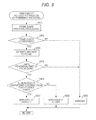
- the main subject distance distribution determining processing according to the present embodiment will be described with reference to FIG. 9 .
- step S 401 the control section 100 performs the frame shape specifying processing.
- step S 402 the control section 100 is configured to determine whether or not a frame exists at a peripheral part of an image. When it is determined that no frame exists, the processing proceeds to S 403 .
- step S 403 the control section 100 is configured to conclude that the distance to the main subject is unknown. The main subject distance distribution determining processing thereafter ends, and the processing returns to the camera control processing.
- step S 402 When it is determined in step S 402 that the frame exists, the processing proceeds to step S 404 .
- the control section 100 is configured to estimate a distance from the imaging apparatus 1 to the detected frame. The distance to the frame is derived by focusing the frame, for example.
- step S 405 the control section 100 is configured to determine whether or not an inner peripheral part of the frame is dark. That is, the detected frame is herein the window frame as in FIG. 7 or 8 or the like, and it is determined whether or not the image is in a state in which an outside is seen from an inside of a building or the like. In a case in which the frame is the window frame or the like, and in which the outside is seen from the inside of a building, the inner peripheral part of the frame is darker than the frame.
- step S 403 the processing proceeds to step S 403 , and it is concluded that the distance to the main subject is unknown. Conversely, when it is determined that the inner peripheral part is dark, the processing proceeds to step S 406 .
- step S 406 the control section 100 is configured to determine whether or not an illumination at the center part is different from that at the frame part.
- the main subject is the set of the outdoor buildings and signboards as illustrated in FIG. 7
- the illumination at the center part comprising the main subject and the illumination at the frame part are different in terms of the quality such as color temperature.
- the main subject is the indoor person or object as illustrated in FIG. 8
- the illumination at the center part comprising the main subject and the illumination at the frame part are similar in terms of the quality.
- the processing proceeds to step S 407 .
- step S 407 the control section 100 is configured to determine that the main subject is farther than the frame. The main subject distance distribution determining processing thereafter ends, and the processing returns to the camera control processing.
- step S 408 the control section 100 is configured to determine that the main subject is nearer than the frame.
- the main subject distance distribution determining processing thereafter ends, and the processing returns to the camera control processing. Meanwhile, instead of the above processing, it may be determined in step S 406 whether or not the center part is dark, and when the center part is dark, the processing may proceed to step S 408 .
- the frame shape specifying processing performed here may be similar to the frame shape specifying processing in the first embodiment described with reference to FIG. 6 .
- the window frame 324 cannot be specified by the frame shape specifying processing in the first embodiment described with reference to FIG. 6 .
- a processing method enabling the window frame 324 to be specified even in the cases of FIGS. 7 and 8 will be shown. It is to be understood that the method shown here can be used in combination with the method in the first embodiment.
- step S 501 the control section 100 searches contrast changing points in a left edge direction or a right edge direction and in an upper edge direction or a lower edge direction of an image, with reference to the center of the image.
- step S 502 the control section 100 is configured to determine whether or not the brightness change has been detected. When no brightness change is detected, the processing proceeds to step S 507 . Conversely, when the brightness change is detected, the processing proceeds to step S 503 .
- step S 503 the control section 100 is configured to search the contrast changing points in the left edge direction or the right edge direction, setting an upper part or a lower part of the image as a reference in a similar manner to that in step S 501 .
- the control section 100 is also configured to search the contrast changing points in the upper edge direction or the lower edge direction, setting a left part or a right part of the image as a reference.
- step S 504 the control section 100 is configured to determine whether or not the contrast changing points are arranged linearly when the found contrast changing points are connected. When each line is not linear, the processing proceeds to step S 507 . Conversely, when it is linear, the processing proceeds to step S 505 .
- step S 505 the control section 100 is configured to determine whether or not the plurality of straight lines obtained by connecting the contrast changing points are parallel or perpendicular. When the straight lines are not parallel or perpendicular, the processing proceeds to step S 507 . Conversely, when they are parallel or perpendicular, the processing proceeds to step S 506 .
- determination of whether or not they are parallel or perpendicular does not need to be strict determination but may be determination of whether or not they are approximately parallel or approximately perpendicular.
- step S 506 the control section 100 is configured to conclude that the image comprises a frame shape.
- the frame shape specifying processing thereafter ends, and the processing returns to the main subject distance distribution determining processing.
- the straight lines obtained by connecting the contrast changing points are parallel or perpendicular, it is estimated that these contrast changing points represent window frames, poles, ceilings, beams, and the like.
- the window frames, the poles, the ceilings, the beams, and the like are arranged to be parallel to or perpendicular to each other.
- the imaging apparatus 1 may be configured to determine whether or not the straight lines showing the contrast changing points are arranged to be parallel or perpendicular and to conclude that the image comprises a frame shape when they are arranged to be parallel or perpendicular.
- step S 507 the control section 100 is configured to conclude that the image comprises no frame shape.
- the frame shape specifying processing thereafter ends, and the processing returns to the main subject distance distribution determining processing.
- the photographing time is nighttime, and in which a night view is photographed through a window, or in which an indoor subject is photographed with the night view therebehind
- the structure such as the window frame is focused relatively easily.
- the distance to the subject is estimated with reference to the structure, and the distance relation between the subject and the structure can be determined by brightness of the structure and the main subject, how the images of the structure and the main subject move, and how the images overlap in a similar manner to that in the previous embodiment.
- Indoor illumination components may be used.
- a spectral component of an illumination lighting an inside of the structure and a spectral component of an illumination lighting the main subject are compared, and when they are the same, it can be determined that the main subject is in front of the structure, and when they are different, it can be determined that the main subject is outside the structure.
- Such comparison targets are collectively referred to as image characteristics.
- a third embodiment of the present invention will be described. Here, different points from those in the first embodiment will be described. Similar or identical components to those in the first embodiment are shown with the same reference numerals, and description of the duplicate components is omitted.
- the first embodiment described is the example of, in photographing the subject inside or outside the window, estimating the distance to the main subject with reference to the window frame.
- the present embodiment described is an example of, in an indoor location, estimating a distance to the main subject with reference to a structure existing continuously from a near side to a far side.
- a technique according to the present embodiment can be used in a case in which contrast of the main subject is low, and in which focusing by means of auto-focusing is difficult, such as a backlight case.
- a structure straight line in a building such as a line on a ceiling described herein is a typical example of a structure having a straight line having obvious specific rules such as having an equal width, extending in a far or near direction, and having information in the far or near direction and in a direction perpendicular to the far or near direction.
- FIG. 11 a case in which structures 334 , such as patterns on a ceiling and beams, existing continuously from the nearside to the far side, exist in an imaging region 330 , is considered.
- the structures 334 existing continuously from the near side to the far side look radial so as to be focused on one vanishing point in perspective.
- contrast differs with a distance thereof.
- Camera control processing according to the present embodiment is similar to that in the case of the first embodiment.
- main subject distance distribution determining processing is different from that in the first embodiment.
- the main subject distance distribution determining processing according to the present embodiment will be described with reference to FIG. 12 .
- step S 601 the control section 100 is configured to perform radial structure specifying processing.
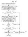
- the radial structure specifying processing will be described with reference to a flowchart illustrated in FIG. 13 .
- the radial structure specification is a method for determining characteristics of structures with use of characteristics of an image in which the lines look as if they were gradually narrowed and is a determining method with perspective. This method can be used in many scenes such as indoor ceiling and wall, a top-down view of a rooftop of a building, a side surface of a building, and a road.
- step S 701 the control section 100 is configured to specify contrast changing points in a horizontal direction at a 1/10 part from an upper edge in the up-down direction of the image and specifies the contrast changing points in the horizontal direction at a 1 ⁇ 5 part from the upper edge in the up-down direction of the image.
- step S 702 the control section 100 is configured to make the contrast changing points at the 1/10 part from the upper edge correspond to the contrast changing points at the 1 ⁇ 5 part from the upper edge specified in step S 701 . For example, at the 1/10 part and the 1 ⁇ 5 part from the upper edge, similar contrast changing points are made to correspond to each other sequentially from the center part in the right-left direction of the image to prepare a plurality of sets of the contrast changing points. In addition, straight lines each connecting the contrast changing points that have been made to correspond to each other are defined.
- step S 703 the control section 100 is configured to determine whether or not the plurality of straight lines each connecting the contrast changing points defined in step S 702 are arranged radially so as to be focused on one point.
- the processing proceeds to step S 704 .
- step S 704 the control section 100 is configured to conclude that the image comprises a radial structure.
- the radial structure specifying processing thereafter ends, and the processing returns to the main subject distance distribution determining processing.
- step S 705 the control section 100 is configured to conclude that the image comprises no radial structure.
- the radial structure specifying processing thereafter ends, and the processing returns to the main subject distance distribution determining processing.
- step S 602 the control section 100 is configured to determine whether or not a radial structure exists. That is, the control section 100 is configured to determine whether or not a radial structure has been specified in the radial structure specifying processing. When it is determined that no radial structure exists, the processing proceeds to S 603 . In step S 603 , the control section 100 is configured to conclude that the distance to the main subject with use of the radial lines is unknown.
- a structure behind the main subject (here, it is found from how the objects overlap that the window frame is further behind) may be detected, and it may be determined from a distance to the window frame that the main subject is nearer than the window frame.
- This further provides an invention of a situation comprehending apparatus comprising a structure detecting section detecting a second structure existing in front of or behind the main subject. Since this way of thinking is effective regardless of whether or not radial lines are detected, using only how the main subject overlaps with structures without performing the perspective radial line detection is available. In an indoor location, many structures such as desks and lockers exist, which facilitates distance comprehension.
- the main subject distance distribution determining processing thereafter ends, and the processing returns to the camera control processing.
- step S 604 the control section 100 estimates a distance from the imaging apparatus 1 to any position of the radial structure. Examples of the position are a middle point of the radial structure in the photographing region and a position at which contrast changes significantly at the current focused position. The distance to this position is derived by focusing the radial structure, for example.
- step S 605 the control section 100 is configured to determine whether or not contrast at the center part of the image at which the main subject exists and contrast at a far part of the structure are similar. When the contrast is similar, the processing proceeds to step S 606 .
- step S 606 the control section 100 is configured to determine that the main subject is far. The main subject distance distribution determining processing thereafter ends, and the processing returns to the camera control processing. Meanwhile, in a case in which an outline of the main subject is unclear, such contrast comparison is difficult.
- changes in contrast may be confirmed along the outline of the main subject, or relative changes in contrast may be confirmed by changing a focused position for imaging, to compare the contrast of the main subject with the contrast of the structure and to comprehend the distance relation between the main subject and the structure.
- step S 605 When it is determined in step S 605 that the contrast at the center part and the contrast at the far part of the structure are not similar, the processing proceeds to step S 607 .
- step S 607 the control section 100 is configured to determine that the main subject is near. The main subject distance distribution determining processing thereafter ends, and the processing returns to the camera control processing.
- the difficulty in the auto-focusing in the above situation can be reduced.
- contrast distribution of the image is used, and the distance relation between the structure and another object is comprehended.
- the distance to the subject is estimated with reference to the structure, and the distance relation between the subject and the structure can be determined by brightness of the structure and the main subject, how the images of the structure and the main subject move, how the images overlap, and contrast of the structure and the main subject (these are regarded as the image characteristics) in a similar manner to that in the previous embodiment.
- a second structure may be found behind the main subject, and how the main subject overlaps with the second structure may be determined and may be used as the image characteristic.
- This case can provide a situation comprehending apparatus comprising an image acquiring section acquiring an image of a target scene, a structure specifying section specifying a structure comprising linear image information in a far or near direction of the scene or in a direction perpendicular to the far or near direction, a distance acquiring section acquiring a distance to a structure straight line comprised in the structure, a main subject specifying section specifying a main subject different from the structure comprised in the image, and a distance distribution determining section determining an image of a second structure with use of an image of the structure and an image of the main subject and determining a distance to the target from characteristics of the images of the main subject and the second structure.
- the posture determining section 230 is not necessarily an essential component.
- first to third embodiments may be used in combination with each other.
- the main subject distance distribution determining processing described in the first embodiment or the main subject distance distribution determining processing described in the second embodiment may be used selectively.
- the main subject distance distribution determining processing operations in the first to third embodiments may be performed sequentially so as to select an optimal estimated value of the distance to the main subject.
- each control operation described with reference to the flowchart out of the techniques described in each embodiment can be achieved with use of a program.
- This program can be recorded in a recording medium or a recording section.
- Various methods for recording the program in the recording medium or the recording section can be used.
- the program may be recorded before shipping the product, may be recorded when the distributed recording medium is used, or may be recorded by downloading via the Internet.
- the above configuration of the imaging apparatus 1 can be applied in an information mobile terminal such as a smartphone and a tablet terminal.
- an information mobile terminal such as a smartphone and a tablet terminal.
- Another example of the information mobile terminal is a wearable terminal.
- Such a technique is particularly important in the wearable device, in which operations by a person who takes pictures are not easy.
- the configuration can also be used effectively in a monitoring camera for use inside a structure, an industrial device for inspections, and an industrial endoscope, not only in a consumer camera.
- the configuration can be applied in a microscope and various observation devices for medical use.
- the above configuration of the imaging apparatus 1 can also be used for inspections (e.g., an inspection for occurrence of temporal change), observations, and the like of a construction such as a building, a house, and a bridge.
- inspections e.g., an inspection for occurrence of temporal change
- observations e.g., observations, and the like of a construction
- the configuration can be used effectively in focusing when it can be defined that the construction extends in the far or near direction, instead of focusing under the force of gravity.
- the configuration can be used not only in focusing but also for a method and apparatus for immediately comprehending distance relation and distance distribution between a structure and another object.
- the lens unit 212 may be a replaceable lens unit or a lens unit integrally attached to the imaging section 214 .
- the posture of the imaging apparatus 1 may be estimated based on subject information in an image acquired by the image acquiring section 102 .
- the frame shape does not necessarily comprise structure straight lines.
- the main subject distance distribution determining section 124 may be configured to determine that the main subject is located farther than the frame shape when the illumination at the inner peripheral part of the frame shape is different from that at the main subject and that the main subject is located nearer than the frame shape when the illumination at the inner peripheral part of the frame shape is the same as that at the main subject. For determination of whether or not the illuminations are the same, it may be determined that “the illuminations are the same” when the brightness values are within a predetermined range and that “the illuminations are different” when the brightness values are out of the predetermined range. That is, for the determination that the illuminations are the same, the illuminations do not necessarily have to be identical in a strict sense. A reference for the determination that the illuminations are the same can be preset in the control section 100 .
- An imaging apparatus comprising a processor comprising hardware, wherein the processor is configured to implement:
- an image acquiring section configured to acquire an image which is based on a subject image
- a structure specifying section configured to specify a structure comprised in the image
- a distance acquiring section configured to acquire a structure distance which is a distance to the structure
- a main subject determining section configured to determine a state of a main subject comprised in the image
- a main subject distance determining section configured to determine an index of a distance to the main subject with use of the structure distance based on the state of the main subject.
- a subject distance estimating method comprising:
- a computer readable device for subject distance estimation having a computer execute operations comprising:
Landscapes
- Physics & Mathematics (AREA)
- General Physics & Mathematics (AREA)
- Studio Devices (AREA)
- Measurement Of Optical Distance (AREA)
- Focusing (AREA)
- Automatic Focus Adjustment (AREA)
Abstract
Description
Claims (21)
Applications Claiming Priority (2)
| Application Number | Priority Date | Filing Date | Title |
|---|---|---|---|
| JP2015019508A JP2016142658A (en) | 2015-02-03 | 2015-02-03 | Situation grasping device, situation grasping method, and program for grasping situation |
| JP2015-019508 | 2015-02-03 |
Publications (2)
| Publication Number | Publication Date |
|---|---|
| US20160223883A1 US20160223883A1 (en) | 2016-08-04 |
| US9769373B2 true US9769373B2 (en) | 2017-09-19 |
Family
ID=56553080
Family Applications (1)
| Application Number | Title | Priority Date | Filing Date |
|---|---|---|---|
| US15/014,202 Expired - Fee Related US9769373B2 (en) | 2015-02-03 | 2016-02-03 | Situation comprehending apparatus, situation comprehending method, and program for situation comprehension |
Country Status (2)
| Country | Link |
|---|---|
| US (1) | US9769373B2 (en) |
| JP (1) | JP2016142658A (en) |
Citations (6)
| Publication number | Priority date | Publication date | Assignee | Title |
|---|---|---|---|---|
| US20040183939A1 (en) * | 2003-02-04 | 2004-09-23 | Osamu Nonaka | Camera having AF function |
| US20100238325A1 (en) * | 2009-03-19 | 2010-09-23 | Casio Computer Co., Ltd. | Image processor and recording medium |
| US20110268369A1 (en) * | 2010-05-03 | 2011-11-03 | Microsoft Corporation | Generating a combined image from multiple images |
| US20120206619A1 (en) * | 2011-01-25 | 2012-08-16 | Nikon Corporation | Image processing apparatus, image capturing apparatus and recording medium |
| JP2013160879A (en) | 2012-02-03 | 2013-08-19 | Nikon Corp | Imaging apparatus |
| US20150109474A1 (en) * | 2013-10-23 | 2015-04-23 | Canon Kabushiki Kaisha | Image processing apparatus, image processing method, and storage medium |
-
2015
- 2015-02-03 JP JP2015019508A patent/JP2016142658A/en active Pending
-
2016
- 2016-02-03 US US15/014,202 patent/US9769373B2/en not_active Expired - Fee Related
Patent Citations (6)
| Publication number | Priority date | Publication date | Assignee | Title |
|---|---|---|---|---|
| US20040183939A1 (en) * | 2003-02-04 | 2004-09-23 | Osamu Nonaka | Camera having AF function |
| US20100238325A1 (en) * | 2009-03-19 | 2010-09-23 | Casio Computer Co., Ltd. | Image processor and recording medium |
| US20110268369A1 (en) * | 2010-05-03 | 2011-11-03 | Microsoft Corporation | Generating a combined image from multiple images |
| US20120206619A1 (en) * | 2011-01-25 | 2012-08-16 | Nikon Corporation | Image processing apparatus, image capturing apparatus and recording medium |
| JP2013160879A (en) | 2012-02-03 | 2013-08-19 | Nikon Corp | Imaging apparatus |
| US20150109474A1 (en) * | 2013-10-23 | 2015-04-23 | Canon Kabushiki Kaisha | Image processing apparatus, image processing method, and storage medium |
Also Published As
| Publication number | Publication date |
|---|---|
| JP2016142658A (en) | 2016-08-08 |
| US20160223883A1 (en) | 2016-08-04 |
Similar Documents
| Publication | Publication Date | Title |
|---|---|---|
| JP7480823B2 (en) | Information processing device, information processing method, and program | |
| Bouman et al. | Turning corners into cameras: Principles and methods | |
| US10654422B2 (en) | View friendly monitor systems | |
| Morse et al. | UAV video coverage quality maps and prioritized indexing for wilderness search and rescue | |
| US11010979B2 (en) | Overlay for camera field of vision | |
| JP2020181595A (en) | How to take a picture through a visual obstacle | |
| US20120307113A1 (en) | Method and system for sequential viewing of two video streams | |
| JP6278242B2 (en) | Shading device, shading method, and program | |
| JP7533646B2 (en) | Evaluation device, evaluation method, and program | |
| KR101803340B1 (en) | Visual odometry system and method | |
| Zhang et al. | Event-based sensor fusion and application on odometry: A survey | |
| US11734833B2 (en) | Systems and methods for detecting movement of at least one non-line-of-sight object | |
| WO2018087545A1 (en) | Object location technique | |
| KR20150145596A (en) | Apparatus for measuring light pollution and method for measuring light pollution using the same | |
| US9769373B2 (en) | Situation comprehending apparatus, situation comprehending method, and program for situation comprehension | |
| CN108055456B (en) | Texture acquisition method and device | |
| EP3173839B1 (en) | Microscope system and control method therefor | |
| US20180060685A1 (en) | View friendly monitor systems | |
| Buquet et al. | Next-generation of sUAS 360 surround vision cameras designed for automated navigation in low-light conditions | |
| Jędrasiak et al. | The comparison of capabilities of low light camera, thermal imaging camera and depth map camera for night time surveillance applications | |
| WO2022198631A1 (en) | Method, apparatus and system for auto-labeling | |
| JP2015002476A (en) | Image processing apparatus | |
| Hu et al. | Cell-based visual surveillance with active cameras for 3D human gaze computation | |
| Song et al. | High-speed object tracking and localization using event-based extended Kalman filtering | |
| Li et al. | Optical flow based velocity estimation for mobile robots |
Legal Events
| Date | Code | Title | Description |
|---|---|---|---|
| AS | Assignment |
Owner name: OLYMPUS CORPORATION, JAPAN Free format text: ASSIGNMENT OF ASSIGNORS INTEREST;ASSIGNORS:KOSHIKAWA, MIZUKI;ITO, KAZUMI;KOUCHI, TAICHIRO;AND OTHERS;SIGNING DATES FROM 20160302 TO 20160328;REEL/FRAME:038328/0455 |
|
| AS | Assignment |
Owner name: OLYMPUS CORPORATION, JAPAN Free format text: CHANGE OF ADDRESS;ASSIGNOR:OLYMPUS CORPORATION;REEL/FRAME:043077/0165 Effective date: 20160401 |
|
| STCF | Information on status: patent grant |
Free format text: PATENTED CASE |
|
| MAFP | Maintenance fee payment |
Free format text: PAYMENT OF MAINTENANCE FEE, 4TH YEAR, LARGE ENTITY (ORIGINAL EVENT CODE: M1551); ENTITY STATUS OF PATENT OWNER: LARGE ENTITY Year of fee payment: 4 |
|
| AS | Assignment |
Owner name: OM DIGITAL SOLUTIONS CORPORATION, JAPAN Free format text: CHANGE OF NAME;ASSIGNOR:OLYMPUS CORPORATION;REEL/FRAME:058152/0131 Effective date: 20210730 |
|
| FEPP | Fee payment procedure |
Free format text: MAINTENANCE FEE REMINDER MAILED (ORIGINAL EVENT CODE: REM.); ENTITY STATUS OF PATENT OWNER: LARGE ENTITY |
|
| LAPS | Lapse for failure to pay maintenance fees |
Free format text: PATENT EXPIRED FOR FAILURE TO PAY MAINTENANCE FEES (ORIGINAL EVENT CODE: EXP.); ENTITY STATUS OF PATENT OWNER: LARGE ENTITY |
|
| STCH | Information on status: patent discontinuation |
Free format text: PATENT EXPIRED DUE TO NONPAYMENT OF MAINTENANCE FEES UNDER 37 CFR 1.362 |
|
| FP | Lapsed due to failure to pay maintenance fee |
Effective date: 20250919 |