US9765841B2 - Damper assembly - Google Patents
Damper assembly Download PDFInfo
- Publication number
- US9765841B2 US9765841B2 US14/846,600 US201514846600A US9765841B2 US 9765841 B2 US9765841 B2 US 9765841B2 US 201514846600 A US201514846600 A US 201514846600A US 9765841 B2 US9765841 B2 US 9765841B2
- Authority
- US
- United States
- Prior art keywords
- chamber
- inner cylinder
- aperture
- damper
- plunger
- Prior art date
- Legal status (The legal status is an assumption and is not a legal conclusion. Google has not performed a legal analysis and makes no representation as to the accuracy of the status listed.)
- Active, expires
Links
Images


Classifications
-
- F—MECHANICAL ENGINEERING; LIGHTING; HEATING; WEAPONS; BLASTING
- F16—ENGINEERING ELEMENTS AND UNITS; GENERAL MEASURES FOR PRODUCING AND MAINTAINING EFFECTIVE FUNCTIONING OF MACHINES OR INSTALLATIONS; THERMAL INSULATION IN GENERAL
- F16F—SPRINGS; SHOCK-ABSORBERS; MEANS FOR DAMPING VIBRATION
- F16F9/00—Springs, vibration-dampers, shock-absorbers, or similarly-constructed movement-dampers using a fluid or the equivalent as damping medium
- F16F9/32—Details
- F16F9/3207—Constructional features
- F16F9/3214—Constructional features of pistons
-
- B—PERFORMING OPERATIONS; TRANSPORTING
- B60—VEHICLES IN GENERAL
- B60G—VEHICLE SUSPENSION ARRANGEMENTS
- B60G21/00—Interconnection systems for two or more resiliently-suspended wheels, e.g. for stabilising a vehicle body with respect to acceleration, deceleration or centrifugal forces
- B60G21/02—Interconnection systems for two or more resiliently-suspended wheels, e.g. for stabilising a vehicle body with respect to acceleration, deceleration or centrifugal forces permanently interconnected
- B60G21/06—Interconnection systems for two or more resiliently-suspended wheels, e.g. for stabilising a vehicle body with respect to acceleration, deceleration or centrifugal forces permanently interconnected fluid
- B60G21/067—Interconnection systems for two or more resiliently-suspended wheels, e.g. for stabilising a vehicle body with respect to acceleration, deceleration or centrifugal forces permanently interconnected fluid between wheels on different axles on the same side of the vehicle, i.e. the left or the right side
-
- B—PERFORMING OPERATIONS; TRANSPORTING
- B60—VEHICLES IN GENERAL
- B60G—VEHICLE SUSPENSION ARRANGEMENTS
- B60G21/00—Interconnection systems for two or more resiliently-suspended wheels, e.g. for stabilising a vehicle body with respect to acceleration, deceleration or centrifugal forces
- B60G21/02—Interconnection systems for two or more resiliently-suspended wheels, e.g. for stabilising a vehicle body with respect to acceleration, deceleration or centrifugal forces permanently interconnected
- B60G21/06—Interconnection systems for two or more resiliently-suspended wheels, e.g. for stabilising a vehicle body with respect to acceleration, deceleration or centrifugal forces permanently interconnected fluid
- B60G21/073—Interconnection systems for two or more resiliently-suspended wheels, e.g. for stabilising a vehicle body with respect to acceleration, deceleration or centrifugal forces permanently interconnected fluid between wheels on the same axle but on different sides of the vehicle, i.e. the left and right wheel suspensions being interconnected
-
- B—PERFORMING OPERATIONS; TRANSPORTING
- B60—VEHICLES IN GENERAL
- B60G—VEHICLE SUSPENSION ARRANGEMENTS
- B60G3/00—Resilient suspensions for a single wheel
- B60G3/18—Resilient suspensions for a single wheel with two or more pivoted arms, e.g. parallelogram
- B60G3/20—Resilient suspensions for a single wheel with two or more pivoted arms, e.g. parallelogram all arms being rigid
-
- F—MECHANICAL ENGINEERING; LIGHTING; HEATING; WEAPONS; BLASTING
- F16—ENGINEERING ELEMENTS AND UNITS; GENERAL MEASURES FOR PRODUCING AND MAINTAINING EFFECTIVE FUNCTIONING OF MACHINES OR INSTALLATIONS; THERMAL INSULATION IN GENERAL
- F16F—SPRINGS; SHOCK-ABSORBERS; MEANS FOR DAMPING VIBRATION
- F16F9/00—Springs, vibration-dampers, shock-absorbers, or similarly-constructed movement-dampers using a fluid or the equivalent as damping medium
- F16F9/06—Springs, vibration-dampers, shock-absorbers, or similarly-constructed movement-dampers using a fluid or the equivalent as damping medium using both gas and liquid
- F16F9/062—Bi-tubular units
-
- F—MECHANICAL ENGINEERING; LIGHTING; HEATING; WEAPONS; BLASTING
- F16—ENGINEERING ELEMENTS AND UNITS; GENERAL MEASURES FOR PRODUCING AND MAINTAINING EFFECTIVE FUNCTIONING OF MACHINES OR INSTALLATIONS; THERMAL INSULATION IN GENERAL
- F16F—SPRINGS; SHOCK-ABSORBERS; MEANS FOR DAMPING VIBRATION
- F16F9/00—Springs, vibration-dampers, shock-absorbers, or similarly-constructed movement-dampers using a fluid or the equivalent as damping medium
- F16F9/06—Springs, vibration-dampers, shock-absorbers, or similarly-constructed movement-dampers using a fluid or the equivalent as damping medium using both gas and liquid
- F16F9/063—Springs, vibration-dampers, shock-absorbers, or similarly-constructed movement-dampers using a fluid or the equivalent as damping medium using both gas and liquid comprising a hollow piston rod
-
- F—MECHANICAL ENGINEERING; LIGHTING; HEATING; WEAPONS; BLASTING
- F16—ENGINEERING ELEMENTS AND UNITS; GENERAL MEASURES FOR PRODUCING AND MAINTAINING EFFECTIVE FUNCTIONING OF MACHINES OR INSTALLATIONS; THERMAL INSULATION IN GENERAL
- F16F—SPRINGS; SHOCK-ABSORBERS; MEANS FOR DAMPING VIBRATION
- F16F9/00—Springs, vibration-dampers, shock-absorbers, or similarly-constructed movement-dampers using a fluid or the equivalent as damping medium
- F16F9/32—Details
- F16F9/36—Special sealings, including sealings or guides for piston-rods
- F16F9/368—Sealings in pistons
-
- B—PERFORMING OPERATIONS; TRANSPORTING
- B60—VEHICLES IN GENERAL
- B60G—VEHICLE SUSPENSION ARRANGEMENTS
- B60G2200/00—Indexing codes relating to suspension types
- B60G2200/10—Independent suspensions
- B60G2200/14—Independent suspensions with lateral arms
-
- B—PERFORMING OPERATIONS; TRANSPORTING
- B60—VEHICLES IN GENERAL
- B60G—VEHICLE SUSPENSION ARRANGEMENTS
- B60G2204/00—Indexing codes related to suspensions per se or to auxiliary parts
- B60G2204/40—Auxiliary suspension parts; Adjustment of suspensions
- B60G2204/45—Stops limiting travel
-
- B—PERFORMING OPERATIONS; TRANSPORTING
- B60—VEHICLES IN GENERAL
- B60G—VEHICLE SUSPENSION ARRANGEMENTS
- B60G2206/00—Indexing codes related to the manufacturing of suspensions: constructional features, the materials used, procedures or tools
- B60G2206/01—Constructional features of suspension elements, e.g. arms, dampers, springs
- B60G2206/10—Constructional features of arms
- B60G2206/12—Constructional features of arms with two attachment points on the sprung part of the vehicle
-
- B—PERFORMING OPERATIONS; TRANSPORTING
- B60—VEHICLES IN GENERAL
- B60G—VEHICLE SUSPENSION ARRANGEMENTS
- B60G2206/00—Indexing codes related to the manufacturing of suspensions: constructional features, the materials used, procedures or tools
- B60G2206/01—Constructional features of suspension elements, e.g. arms, dampers, springs
- B60G2206/10—Constructional features of arms
- B60G2206/124—Constructional features of arms the arm having triangular or Y-shape, e.g. wishbone
-
- B—PERFORMING OPERATIONS; TRANSPORTING
- B60—VEHICLES IN GENERAL
- B60G—VEHICLE SUSPENSION ARRANGEMENTS
- B60G2206/00—Indexing codes related to the manufacturing of suspensions: constructional features, the materials used, procedures or tools
- B60G2206/01—Constructional features of suspension elements, e.g. arms, dampers, springs
- B60G2206/40—Constructional features of dampers and/or springs
- B60G2206/41—Dampers
Definitions
- the present application relates general to the field of suspension systems for vehicles. More specifically the present application relates to hydraulic shock absorbers.
- the dampers function as shock absorbers for vehicles.
- the dampers are typically formed from hydraulic cylinders, such as double-acting cylinders.
- the hydraulic cylinder includes a rod end, a cap end, and a plunger (or piston) on an end of a rod. Movement of the plunger drives hydraulic fluid into and out of the rod and cap ends. Friction from movement of the hydraulic fluid through the cylinder and associated plumbing dissipates energy associated with actuation of the suspension system in a manner proportional to the velocity of the actuation.
- the damper assembly includes a tubular member, an outer cylinder positioned at least partially within the tubular member, an inner cylinder positioned at least partially within the outer cylinder, a cap coupled to the inner cylinder, a plunger received within the inner cylinder and coupled to an end of a rod extending at least partially within the inner cylinder, an annular piston where at least a portion of the annular piston extends between the inner cylinder and the outer cylinder, and a barrier extending between the inner cylinder and the outer cylinder.
- the rod has an outer diameter that is smaller than an inner diameter of the inner cylinder.
- the plunger, the cap, and an interior of the inner cylinder at least partially define a first chamber.
- the barrier, the annular piston, an exterior surface of the inner cylinder, and the outer cylinder at least partially define a second chamber.
- a portion of the plunger at least partially defining the first chamber has a cross-sectional area that is substantially equal to that of the portion of the annular piston at least partially defining the second chamber.
- the plunger is configured to move relative to the inner cylinder and the annular piston is configured to move relative to the outer cylinder.
- the damper assembly includes a tubular member, an outer cylinder positioned at least partially within the tubular member, an inner cylinder positioned at least partially within the outer cylinder, a cap coupled to the inner cylinder, a plunger received within the inner cylinder and coupled to an end of a rod extending at least partially within the inner cylinder, an annular piston fixed to the inner cylinder where the annular piston extends between the inner cylinder and the outer cylinder, and a barrier extending between the inner cylinder and the outer cylinder.
- the rod has an outer diameter that is smaller than an inner diameter of the inner cylinder.
- the plunger, the cap, and an interior of the inner cylinder at least partially define a first chamber.
- the barrier, the annular piston, an exterior surface of the inner cylinder, and the outer cylinder at least partially define a second chamber.
- the plunger is configured to move relative to the inner cylinder and the annular piston is configured to move relative to the outer cylinder.
- the suspension system includes a first damper, a second damper, a first conduit, and a second conduit.
- the first damper includes a first chamber and a second chamber.
- the first chamber has a first movable surface for changing the volume of the first chamber.
- the first movable surface includes a first plunger received within a first inner cylinder and coupled to an end of a first rod extending at least partially within the first inner cylinder.
- the first rod has an outer diameter that is smaller than an inner diameter of the first inner cylinder.
- the second chamber has a second movable surface for changing the volume of the second chamber.
- the second movable surface includes a first piston having an annular cross-section and positioned between the first inner cylinder and a first outer cylinder.
- the second damper includes a third chamber and a fourth chamber.
- the third chamber has a third movable surface for changing the volume of the third chamber.
- the third movable surface includes a second plunger received within a second inner cylinder and coupled to an end of a second rod extending at least partially within the second inner cylinder.
- the second rod has an outer diameter that is smaller than an inner diameter of the second inner cylinder.
- the fourth chamber has a fourth movable surface for changing the volume of the fourth chamber.
- the fourth movable surface includes a second piston having an annular cross-section and positioned between the second inner cylinder and a second outer cylinder.
- the first conduit couples the first chamber and one of the third chamber and the fourth chamber.
- the second conduit couples the second chamber and the other of the third chamber and the fourth chamber.
- the cross-sectional areas of the first, second, third, and fourth movable surfaces are substantially equal to each other.
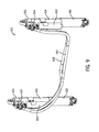
- FIG. 1 is a perspective view of an axle assembly according to an exemplary embodiment of the invention.
- FIG. 2 is a perspective view of a suspension system of the axle assembly of FIG. 1 .
- FIG. 3 is a sectional view of a damper according to an exemplary embodiment of the invention.
- FIG. 4 is a sectional view of the damper of FIG. 3 , taken along line 4 - 4 as shown in FIG. 3 .
- FIG. 5 is a sectional view of a damper according to another exemplary embodiment of the invention.
- FIG. 6 is a sectional view of the damper of FIG. 5 , in another configuration.
- FIG. 7 is a sectional view of a damper according to yet another exemplary embodiment of the invention.
- FIG. 8 is a sectional view of a damper according to still another exemplary embodiment of the invention.
- FIG. 9 is a perspective view of dampers of the axle assembly of FIG. 1 .
- FIG. 10 is a schematic diagram of a vehicle suspension system and a damper according to another exemplary embodiment of the invention.
- an axle assembly 110 is configured for use with a vehicle.
- the vehicle may be a military vehicle, a utility vehicle such as a fire truck, a tractor, construction equipment, a sport utility vehicle, or another type of vehicle.
- the axle assembly 110 includes a differential 112 connected to half shafts 114 , which are each connected to a wheel end assembly 116 .
- the wheel end assembly 116 may include brakes, a gear reduction, steering components, a wheel hub, a wheel, and other features.
- the differential 112 is further configured to be connected with a drive shaft of the vehicle, receiving rotational energy from a prime mover of the vehicle, such as a diesel engine. The differential 112 then allocates torque provided by the prime mover between the half shafts 114 of the axle assembly 110 .
- the half shafts 114 deliver the rotational energy to each wheel-end assembly 116 .
- Movement of the wheel end assembly 116 is at least partially controlled by a suspension system 118 .
- the suspension system 118 includes a spring 120 , a damper 122 , an upper support arm 124 , and a lower support arm 126 .
- the upper and lower support arms 124 , 126 couple the wheel end assembly 116 to the vehicle body, such as to a chassis, a side plate, a hull, or another part of the vehicle body.
- the vehicle may be configured for operation on both paved and rough, off-road terrain. As the vehicle travels over uneven terrain, the upper and lower support arms 124 , 126 guide the vertical movement of the wheel end assembly 116 and a stopper 128 provides an upper bound.
- the suspension system 118 includes one or more high-pressure gas or hydraulic fluid components.
- the spring 120 is a high-pressure gas spring 120 .
- the suspension system 118 further includes at least one high-pressure gas pump 130 , such as a separate high-pressure gas pumps 130 associated with each spring 120 .
- the gas of the pump 130 and spring 120 is at least 90% formed from an inert gas, such as nitrogen, argon, helium, etc., which may be stored, provided, or received in one or more reservoirs (e.g., central reservoir, tank).
- the pump 130 selectively provides gas, under pressure, to the high-pressure gas spring 120 and/or to reservoirs, tanks, accumulators, or other devices.
- additional fluid e.g., gas, hydraulic fluid
- a damper assembly 210 may be used with a suspension system (see, e.g., suspension system 118 of FIGS. 1-2 ), and includes an outer cylinder 212 and an inner cylinder 214 .
- the inner cylinder 214 is at least partially positioned within the outer cylinder 212 .
- a cap 216 FIG. 3 ) closes (e.g., seals, caps) one end of each of the inner and outer cylinders 214 , 212 .
- the inner cylinder 214 is received within a plunger 218 that moves relative to the inner cylinder 214 .
- a first chamber 220 is at least partially defined by the plunger 218 , the cap 216 , and an interior of the inner cylinder 214 . Movement of the plunger 218 relative to the inner cylinder 214 changes the volume of the first chamber 220 .
- the damper assembly 210 further includes an annular piston 222 , which moves relative to the outer cylinder 212 .
- the annular piston 222 is round and includes a ring-shaped cross-section. At least a portion of the annular piston 222 transversely extends between the inner and outer cylinders 214 , 212 .
- a barrier 224 such as a rod-end head or rod gland, also transversely extends between the inner and outer cylinders 214 , 212 .
- a second chamber 226 is at least partially defined by the barrier 224 , the annular piston 222 , an exterior surface of the inner cylinder 214 , and the outer cylinder 212 .
- the second chamber 226 is an annular chamber, and may include one or more sub-chambers divided by structural partitions, but in fluid communication with one another (see generally second chamber 428 as shown in FIG. 7 ).
- the damper assembly 210 further includes a first aperture 228 (e.g., opening, hole, conduit) associated with the first chamber 220 and a second aperture 230 associated with the second chamber 226 .
- the first aperture 228 is formed in the cap 216 and is connected to external transfer tubes or pipes (see generally hydraulic lines 132 as shown in FIGS. 1-2 ).
- the first aperture 228 allows fluid (e.g., hydraulic fluid, oil, gas, etc.) to flow into and out of the first chamber 220 .
- the second aperture 230 is formed in the barrier 224 and is connected to external transfer tubes or pipes.
- the second aperture 230 allows fluid to flow into and out of the second chamber 226 .
- Either or both of the first and second apertures 228 , 230 may include valves (e.g., directional-control valves; see, generally modular valve assembly 624 , 626 as shown in FIG. 9 ).
- the damper assembly 210 functions as a spring or an accumulator, and the first or the second chamber 220 , 226 may not include an aperture.
- the annular piston 222 is fixed to the plunger 218 . As the plunger 218 moves forward, pushing fluid out of the first chamber 220 , the annular piston 222 also moves forward at the same rate, pulling fluid into the second chamber 226 . In other embodiments, the annular piston 222 is fixed to the inner cylinder 214 , which may move relative to both the plunger 218 and to the outer cylinder 212 (see generally annular piston 324 and inner cylinder 314 as shown in FIG. 5 ).
- the portion of the plunger 218 at least partially defining the first chamber 220 has a cross-sectional area that is substantially equal to that of the portion of the annular piston 222 at least partially defining the second chamber 226 (e.g., one-to-one working area ratio).
- the rate of volume change within the first chamber 220 matches the rate of volume change within the second chamber 226 as the annular piston 222 moves.
- the rate of hydraulic fluid out of one chamber 220 , 226 matches the rate of hydraulic fluid entering the other chamber 226 , 220 .
- the first aperture 228 may be coupled to the second aperture 230 .
- Hydraulic fluid from one of the first and second chambers 220 , 226 may flow directly to the other of the first and second chambers 220 , 226 without use of an intermediate accumulator or reservoir, and without using a double-rod end cylinder configuration. No make-up volume of hydraulic fluid is required.
- a third chamber 232 is at least partially defined by the cap 216 , the interior of the outer cylinder 212 , the exterior of the inner cylinder 214 and the annular piston 222 .
- the side of the annular piston 222 that is at least partially defining the third chamber 232 has about a twenty-five percent larger working area than the side of the annular piston 222 that is defining the second chamber 226 .
- the second and third chambers 226 , 232 may contain hydraulic fluid, with the first chamber 220 forming a vacuum, containing inert gas, or in communication with ambient air.
- the extend-to-retract area ratio is about 1-to-1.25 (e.g., near equal area). In designs where the outer diameter of the inner cylinder 214 and the inner diameter of the outer cylinder 212 increase, the extend-to-retract area may more closely approximate a 1-to-1 ratio.
- a damper assembly 310 as may be used with the suspension system 118 of FIGS. 1-2 , includes an outer cylinder 312 and an inner cylinder 314 .
- the inner cylinder 314 is positioned at least partially within the outer cylinder 312 and a plunger 316 is received in the inner cylinder 314 .
- a cap 318 closes the end of the inner cylinder 314 on a side of the inner cylinder 314 that is opposite to the plunger 316 , such that a first chamber 320 is at least partially defined by the face of the plunger 316 , the cap 318 , and the interior of the inner cylinder 314 .
- a rod 322 is fixed to the plunger 316 and extends at least partially within the inner cylinder 314 .
- the rod 322 is fixed to the outer cylinder 312 .
- the damper assembly 310 further includes an annular piston 324 fixed to the inner cylinder 314 on an end of the inner cylinder 314 opposite to the cap 318 .
- the annular piston 324 moves with the inner cylinder 314 relative to both the outer cylinder 312 and the rod 322 .
- the annular piston 324 and a barrier 326 transversely extend between the inner and outer cylinders 314 , 312 , and a second chamber 328 is at least partially defined by the barrier 326 , the annular piston 324 , the exterior of the inner cylinder 314 , and the interior of the outer cylinder 312 .
- the plunger 316 has a cross-sectional area that is substantially equal to the cross-sectional area of the portion of the annular piston 324 that is at least partially defining the second chamber 328 (i.e., one-to-one working area ratio).
- the damper assembly 310 includes a first aperture 330 (e.g., conduit, tunnel, passage) coupling the first chamber 320 to a first port 332 located on the exterior of the damper assembly 310 , and a second aperture 334 coupling the second chamber 328 to a second port 336 also located on the exterior of the damper assembly 310 .
- the first and second ports 332 , 336 are proximate to one another, allowing for coupling of a modular valve assembly 338 ( FIG. 6 ) or another attachment to the damper assembly 310 that may simultaneously access the first and second chambers 320 , 328 via the first and second ports 332 , 336 .
- the first aperture 330 extends from the first port 332 through the rod 322 and the plunger 316 to the first chamber 320 .
- the second aperture 334 extends from the second port 336 , through the interior to the outer cylinder 312 to the second chamber 328 .
- the second aperture 334 extends along an outside portion of the second chamber 328
- the second aperture 334 extends along an inside portion of the second chamber 328 , such as being integrated with the rod 322 (see, e.g., aperture 440 as shown in FIG. 7 ).
- damping assembly 310 During operation of the damping assembly 310 , fluid flows into the first port 332 , through the first aperture 330 in the rod 322 and the plunger 316 , and into the first chamber 320 .
- the inner cylinder 314 slides away from the plunger 316 , and the volume of the first chamber 320 increases. Simultaneously the annular piston 324 slides toward the barrier 326 , decreasing the volume of the second chamber 328 . Fluid flows from the second chamber 328 , through the second aperture 334 and to the second port 336 .
- the first aperture 330 may be coupled to the second aperture 334 , and hydraulic fluid from one of the first and second chambers 320 , 328 may flow directly to the other of the first and second chambers 320 , 328 .
- a damper assembly 410 includes an outer cylinder 412 , an inner cylinder 414 having a cap 416 , and a plunger 418 received in the inner cylinder 414 .
- a first chamber 442 is at least partially defined by the inner cylinder 414 , the cap 416 , and the face of the plunger 418 .
- An annular piston 420 is fixed to the inner cylinder 414 on an end of the inner cylinder 414 opposite to the cap 416 .
- a first part 422 of the annular piston 420 and a barrier 424 both transversely extend between the inner and outer cylinders 414 , 412 .
- a first portion 426 (e.g., sub-chamber) of a second chamber 428 is at least partially defined by the barrier 424 , the first part 422 of the annular piston 420 , the exterior of the inner cylinder 414 , and the interior of the outer cylinder 412 .
- the damper assembly 410 of FIG. 7 further includes a second part 430 of the annular piston 420 , which transversely extends between the inner cylinder 414 and a rod 432 fixed to the plunger 418 .
- the second chamber 428 includes a second portion 434 that is at least partially defined by the rod 432 , the second part 430 of the annular piston 420 , the interior of the inner cylinder 414 , and the rear of the plunger 418 .
- the first and second portions 426 , 434 of the second chamber 428 are in fluid communication with one another such that hydraulic fluid from one of the portions 426 , 434 may flow to the other, and vice versa, through an opening 436 .
- the face of plunger 418 has a cross-sectional area that is substantially equal to the net cross-sectional area of the parts 422 , 430 of the annular piston 420 that are at least partially defining the first and second portions 426 , 434 of the second chamber 428 .
- Apertures 438 , 440 are formed in the damper assembly 410 corresponding to each of the chambers 428 , 442 .
- the aperture 438 associated with the first chamber 442 extends through the rod 432 and connects the first chamber 442 with a first port 444 .
- the aperture 440 associated with the second chamber 428 extends through the rod 432 and connects the second chamber 428 with a second port 446 .
- the first and second ports 444 , 446 are on opposite sides of the damper assembly 410 .
- a damper assembly 510 is designed for position-dependent damping.
- the damper assembly 510 includes a first port 512 , which may be connected to external compression valving (see, e.g., modular valve assembly 338 as shown in FIG. 6 ).
- a first aperture 514 connects the first port 512 to a first chamber 516 (e.g., extension flow collection volume).
- a deflected disc check valve 518 is positioned between the first aperture 514 and the first chamber 516 , allowing flow into the first chamber 516 and preventing flow out of the first chamber 516 .
- a plunger 520 at least partially defines the first chamber 516 , which includes primary flow openings 524 and a series of auxiliary openings 522 for changing the damping response as a function of the number of the auxiliary openings 522 in operation. More auxiliary openings 522 in operation provide lesser resistance to the flow. The operability of the auxiliary openings 522 depends upon the relative configuration of the plunger 520 within the first chamber 516 , which corresponds with the degree to which the damper assembly 510 is extended.
- the damper assembly 510 further includes a second port 524 , which may be connected to external recoil valving.
- a second aperture 526 connects the second port 524 to a second chamber 528 (e.g., recoil flow collection volume) of the damper assembly 510 .
- a second chamber 528 e.g., recoil flow collection volume
- an annular piston 530 is associated with the second chamber 528 .
- the second chamber 528 also includes one or more position-dependent recoil flow ports 532 .
- the damper assembly 510 includes an inner cylinder 534 and an outer cylinder 536 . However, only a portion of the inner cylinder 534 (e.g., less than half) extends within the outer cylinder 536 . Also, a rod 538 of the damper assembly 510 is hollow and includes an empty volume 540 . In contemplated embodiments, the empty volume 540 may be used to support a gas spring (see, e.g., spring 120 as shown in FIG. 1 ) or a portion thereof, integrating the gas spring with the hydraulic damper 510 .
- a gas spring see, e.g., spring 120 as shown in FIG. 1
- a damper set 610 (e.g., system), configured for use with the axle assembly 110 , includes at least two dampers, such as a first damper 612 and a second damper 614 .
- each damper 612 , 614 includes a two chambers 616 , 618 , 620 , 622 , such as rod-end chambers 616 , 620 and cap-end chambers 618 , 622 (see, e.g., chambers 320 , 328 as shown in FIG. 5 ).
- Each chamber 616 , 618 , 620 , 622 includes a surface or wall that moves to change the volume of the chamber, such as a piston or plunger (see, generally plunger 316 and annular piston 324 as shown in FIG. 5 ).
- the movable surfaces of the two chambers 616 , 618 and 620 , 622 may be formed on opposite sides of the same element (e.g., a piston), or may be surfaces of separate elements (e.g., two different pistons).
- the movable surfaces of each of the chambers 616 , 618 , 620 , 622 in the damper set 610 have substantially the same cross-sectional area (e.g., working area).
- the damper set includes a modular valve assembly 624 , 626 fastened to each damper 612 , 614 .
- the modular valve assemblies 624 , 626 include valves (e.g., passive valving, piston valve, deflected disc blow-off valve acting on the rebound side) that control fluid flow to and from the chambers 616 , 618 and 620 , 622 of associated dampers 612 , 614 .
- the modular valve assemblies 624 , 626 may be controlled by a computerized controller and may be configured to operate the damper set 610 in different modes depending upon loading of the associated vehicle (e.g., controlling damping stiffness and response as a function of axle load and/or terrain).
- the modular valve assemblies 624 , 626 are designed to be easily switchable with other modular valve assemblies including different strength valves, depending upon axle load or other factors.
- the modular valve assemblies 624 , 626 are bolted to the dampers 612 , 614 , such as over ports associated with the chambers 616 , 618 , 620 , 622 of the dampers 612 , 614 (see, e.g., ports 332 , 336 as shown in FIGS. 5-6 ).
- the dampers 612 , 614 of the damper set 610 are cross-plumbed (e.g., cross-linked).
- Hydraulic lines 628 , 630 connect opposite chambers 618 , 620 and 616 , 622 of different dampers 612 , 614 , such as connecting a rod-end of one damper with a cap-end of another damper on an opposite side of the axle assembly 110 .
- the dampers 612 , 614 may be cross-plumbed in a “walking beam” configuration for a tandem axle, and/or between dampers 122 on separate axle assemblies of the vehicle (e.g., between dampers located front-to-back, or diagonally located with respect to each other, etc.).
- the hydraulic lines 628 , 630 are coupled to the dampers 612 , 614 by way of the modular valve assemblies 624 , 626 .
- each hydraulic line 628 , 630 includes an associated accumulator 632 , 634 .
- the accumulators 632 , 634 may be fastened to the dampers 612 , 614 , or may be located elsewhere in the axle assembly 110 .
- the accumulators 632 , 634 may be used with the modular valve assemblies 624 , 626 to operate the damper set 610 in different modes, depending upon loading, terrain, speed, etc. of the associated vehicle.
- the damper 612 on the inside of the turn retracts. Retraction of the damper 612 increases pressure in the cap-end chamber 618 and decreases pressure in the rod-end chamber 616 of the damper 612 . Concurrently, the damper 614 on the outside of the turn receives and supplies the hydraulic fluid of the damper 612 . Hydraulic fluid is transferred from the cap-end chamber 618 of the damper 612 to the rod-end chamber 620 of the damper 614 , and from the cap-end chamber 622 of the damper 614 to the rod-end chamber 616 of the damper 612 .
- each of the chambers 616 , 618 , 620 , 622 in the damper set 610 have substantially the same cross-sectional area
- the pressure applied by the cap-end chamber 618 of the damper 612 is oppositely applied to the rod-end chamber 620 of the damper 614 .
- Equal and opposite pressures are intended to improve the ride quality of the associated vehicle by preventing lifting of the vehicle as the vehicle turns, such as raising and lowering of the chassis by unequal pressures loading the dampers 612 , 614 .
- the cap-end chambers 618 , 622 and the rod-end chambers 616 , 620 of the dampers 612 , 614 may be coupled via the hydraulic lines 628 , 630 .
- the modular valve assemblies 624 , 626 allow for switching of the chambers 616 , 618 , 620 , 622 that are respectively coupled, such as from cap-end chamber 618 and rod-end chamber 620 to cap-end chamber 618 and cap-end chamber 622 .
- the switching may be directed via the computerized controller, which may be manually controlled from the cabin of the associated vehicle by an operator and/or automatically controlled by the computerized controller as a function of location, speed, vehicle tilt, etc.
- a damper assembly 710 is designed for use with a rotary actuator 712 (e.g., steering gear).
- the damper assembly 710 includes two chambers 714 , 716 on opposing sides of a piston 718 .
- the piston 718 is coupled to the rotary actuator 712 via a rack-and-pinion gear arrangement 720 .
- the damper assembly 710 dissipates rotary energy and provides equal pressure for hydraulic fluid on both sides of the piston 718 .
- the first chamber 714 may be coupled to the second chamber 716 , and hydraulic fluid from one of the first and second chambers 714 , 716 may flow directly to the other of the first and second chambers 714 , 716 , without use of an intermediate accumulator or reservoir (i.e., no make-up volume required).
- the dampers 210 , 310 , 410 , 510 , and 710 are each configured to operate in a damper set, such as the damper set 610 , which may be part of an axle assembly for a vehicle, such as the axle assembly 110 . Additionally, the dampers 210 , 310 , 410 , 510 , and 710 are configured to operate in other applications, such as with landing gears of airplanes, suspension systems of railroad cars, and other industrial machinery. Further, the innovations described herein may be used with dampers and damping systems associated with large structures, such as buildings and bridges, to dissipate energy of an earthquake, wind, rough seas, etc.
- damper assembly as shown in the various exemplary embodiments, are illustrative only. Although only a few embodiments have been described in detail in this disclosure, many modifications are possible (e.g., variations in sizes, dimensions, structures, shapes and proportions of the various elements, values of parameters, mounting arrangements, use of materials, colors, orientations, etc.) without materially departing from the novel teachings and advantages of the subject matter described herein. Some elements shown as integrally formed may be constructed of multiple parts or elements, the position of elements may be reversed or otherwise varied, and the nature or number of discrete elements or positions may be altered or varied. The order or sequence of any process, logical algorithm, or method steps may be varied or re-sequenced according to alternative embodiments. Other substitutions, modifications, changes and omissions may also be made in the design, operating conditions and arrangement of the various exemplary embodiments without departing from the scope of the present invention.
Landscapes
- Engineering & Computer Science (AREA)
- Mechanical Engineering (AREA)
- General Engineering & Computer Science (AREA)
- Vehicle Body Suspensions (AREA)
- Fluid-Damping Devices (AREA)
Abstract
Description
Claims (5)
Priority Applications (5)
| Application Number | Priority Date | Filing Date | Title |
|---|---|---|---|
| US14/846,600 US9765841B2 (en) | 2011-03-14 | 2015-09-04 | Damper assembly |
| US15/707,675 US10422403B2 (en) | 2011-03-14 | 2017-09-18 | Damper assembly |
| US16/517,209 US11209067B2 (en) | 2011-03-14 | 2019-07-19 | Damper assembly |
| US17/462,924 US11378148B2 (en) | 2011-03-14 | 2021-08-31 | Damper assembly |
| US17/841,158 US20220307566A1 (en) | 2011-03-14 | 2022-06-15 | Damper assembly |
Applications Claiming Priority (2)
| Application Number | Priority Date | Filing Date | Title |
|---|---|---|---|
| US13/047,648 US9127738B2 (en) | 2011-03-14 | 2011-03-14 | Damper assembly |
| US14/846,600 US9765841B2 (en) | 2011-03-14 | 2015-09-04 | Damper assembly |
Related Parent Applications (1)
| Application Number | Title | Priority Date | Filing Date |
|---|---|---|---|
| US13/047,648 Continuation US9127738B2 (en) | 2011-03-14 | 2011-03-14 | Damper assembly |
Related Child Applications (1)
| Application Number | Title | Priority Date | Filing Date |
|---|---|---|---|
| US15/707,675 Continuation US10422403B2 (en) | 2011-03-14 | 2017-09-18 | Damper assembly |
Publications (2)
| Publication Number | Publication Date |
|---|---|
| US20150377314A1 US20150377314A1 (en) | 2015-12-31 |
| US9765841B2 true US9765841B2 (en) | 2017-09-19 |
Family
ID=45929005
Family Applications (6)
| Application Number | Title | Priority Date | Filing Date |
|---|---|---|---|
| US13/047,648 Active 2033-06-29 US9127738B2 (en) | 2011-03-14 | 2011-03-14 | Damper assembly |
| US14/846,600 Active 2031-05-01 US9765841B2 (en) | 2011-03-14 | 2015-09-04 | Damper assembly |
| US15/707,675 Active US10422403B2 (en) | 2011-03-14 | 2017-09-18 | Damper assembly |
| US16/517,209 Active 2031-05-20 US11209067B2 (en) | 2011-03-14 | 2019-07-19 | Damper assembly |
| US17/462,924 Active US11378148B2 (en) | 2011-03-14 | 2021-08-31 | Damper assembly |
| US17/841,158 Pending US20220307566A1 (en) | 2011-03-14 | 2022-06-15 | Damper assembly |
Family Applications Before (1)
| Application Number | Title | Priority Date | Filing Date |
|---|---|---|---|
| US13/047,648 Active 2033-06-29 US9127738B2 (en) | 2011-03-14 | 2011-03-14 | Damper assembly |
Family Applications After (4)
| Application Number | Title | Priority Date | Filing Date |
|---|---|---|---|
| US15/707,675 Active US10422403B2 (en) | 2011-03-14 | 2017-09-18 | Damper assembly |
| US16/517,209 Active 2031-05-20 US11209067B2 (en) | 2011-03-14 | 2019-07-19 | Damper assembly |
| US17/462,924 Active US11378148B2 (en) | 2011-03-14 | 2021-08-31 | Damper assembly |
| US17/841,158 Pending US20220307566A1 (en) | 2011-03-14 | 2022-06-15 | Damper assembly |
Country Status (2)
| Country | Link |
|---|---|
| US (6) | US9127738B2 (en) |
| WO (1) | WO2012125482A1 (en) |
Cited By (23)
| Publication number | Priority date | Publication date | Assignee | Title |
|---|---|---|---|---|
| US20180003258A1 (en) * | 2011-03-14 | 2018-01-04 | Oshkosh Defense, Llc | Damper assembly |
| US10611204B1 (en) | 2017-04-28 | 2020-04-07 | Oshkosh Defense, Llc | Systems and methods for adapting tractive elements to a disabling event |
| US10611203B1 (en) | 2017-04-27 | 2020-04-07 | Oshkosh Defense, Llc | Suspension element lockout |
| US10619696B2 (en) | 2013-03-10 | 2020-04-14 | Oshkosh Defense, Llc | Limiting system for a vehicle suspension component |
| US10632805B1 (en) | 2017-04-27 | 2020-04-28 | Oshkosh Defense, Llc | Suspension element systems and methods |
| US10752075B1 (en) | 2017-04-28 | 2020-08-25 | Oshkosh Defense, Llc | Systems and methods for determining vehicle characteristics |
| US11059436B2 (en) | 2019-02-14 | 2021-07-13 | Oshkosh Corporation | Integrated operator centric controls |
| US11199239B2 (en) | 2013-03-10 | 2021-12-14 | Oshkosh Defense, Llc | Suspension element systems and methods |
| US11376943B1 (en) | 2021-08-13 | 2022-07-05 | Oshkosh Defense, Llc | Electrified military vehicle |
| US11465698B2 (en) | 2020-03-09 | 2022-10-11 | Oshkosh Corporation | Stabilizer bar for a load span tag axle |
| US11480165B2 (en) | 2019-09-19 | 2022-10-25 | Oshkosh Corporation | Reciprocating piston pump comprising a housing defining a first chamber and a second chamber cooperating with a first piston and a second piston to define a third chamber and a fourth chamber |
| US11498409B1 (en) | 2021-08-13 | 2022-11-15 | Oshkosh Defense, Llc | Electrified military vehicle |
| US11529836B1 (en) | 2018-12-21 | 2022-12-20 | Oshkosh Corporation | Pitch and roll control system for a vehicle |
| US12030479B1 (en) | 2021-08-13 | 2024-07-09 | Oshkosh Defense, Llc | Prioritized charging of an energy storage system of a military vehicle |
| US12060053B1 (en) | 2021-08-13 | 2024-08-13 | Oshkosh Defense, Llc | Military vehicle with control modes |
| US12083995B1 (en) | 2021-08-13 | 2024-09-10 | Oshkosh Defense, Llc | Power export system for a military vehicle |
| US12130122B1 (en) | 2021-08-13 | 2024-10-29 | Oshkosh Defense, Llc | Military vehicle with battery armor |
| US12311754B1 (en) | 2021-08-13 | 2025-05-27 | Oshkosh Defense, Llc | Power export system for a military vehicle |
| US12319160B1 (en) | 2021-08-13 | 2025-06-03 | Oshkosh Defense, Llc | Convoy operations for electrified military vehicles |
| US12337772B2 (en) | 2019-02-14 | 2025-06-24 | Oshkosh Corporation | Integrated operator centric controls |
| US12351028B1 (en) | 2021-08-13 | 2025-07-08 | Oshkosh Defense, Llc | Military vehicle with modular battery units |
| US12358361B1 (en) | 2021-08-13 | 2025-07-15 | Oshkosh Defense, Llc | Electrified military vehicle with electric weaponry support system |
| US12491943B1 (en) | 2022-08-27 | 2025-12-09 | Oshkosh Defense, Llc | Systems and methods for a military vehicle |
Families Citing this family (19)
| Publication number | Priority date | Publication date | Assignee | Title |
|---|---|---|---|---|
| US8465025B2 (en) | 2010-08-31 | 2013-06-18 | Oshkosh Corporation | Gas spring assembly for a vehicle suspension |
| US8596648B2 (en) | 2010-10-22 | 2013-12-03 | Oshkosh Corporation | Pump for vehicle suspension system |
| KR101239786B1 (en) * | 2011-03-23 | 2013-03-06 | 대호 (주) | Tractor having a reinforced function of shock absorbing |
| CN103826887A (en) * | 2011-09-27 | 2014-05-28 | 爱信精机株式会社 | Suspension system |
| US9174686B1 (en) | 2012-02-22 | 2015-11-03 | Oshkosh Defense, Llc | Military vehicle |
| US8801017B2 (en) | 2012-03-26 | 2014-08-12 | Oshkosh Corporation | Position dependent damper for a vehicle suspension system |
| US8991840B2 (en) * | 2013-03-14 | 2015-03-31 | Oshkosh Defense, Llc | Load dependent damper for a vehicle suspension system |
| EP3825156A1 (en) | 2013-04-23 | 2021-05-26 | ClearMotion, Inc. | Active suspension with structural actuator |
| GB2557903B (en) * | 2014-04-11 | 2020-03-18 | Oshkosh Defence Llc | Suspension element |
| WO2015157689A1 (en) | 2014-04-11 | 2015-10-15 | Oshkosh Defense, Llc | Suspension element |
| AU2017248349B2 (en) | 2016-04-08 | 2021-11-11 | Oshkosh Corporation | Leveling system for lift device |
| US20200198425A1 (en) * | 2018-12-21 | 2020-06-25 | Agco International Gmbh | Trailed agricultural sprayer with independent wheel suspension |
| US11767060B2 (en) * | 2019-04-12 | 2023-09-26 | Textron Innovations Inc. | Lightweight vehicle |
| US11300172B2 (en) * | 2020-01-29 | 2022-04-12 | Lockheed Martin Corporation | Load limiting breakaway device |
| US12122212B2 (en) | 2021-09-09 | 2024-10-22 | Oshkosh Corporation | Systems and methods for vehicle suspension assemblies |
| US20230070279A1 (en) | 2021-09-09 | 2023-03-09 | Oshkosh Corporation | Chassis with structural battery compartment |
| DE102023108871B3 (en) * | 2023-04-06 | 2024-02-15 | Dr. Ing. H.C. F. Porsche Aktiengesellschaft | motor vehicle |
| CN116221322A (en) * | 2023-04-21 | 2023-06-06 | 广东金利祥兴五金精密制造有限公司 | Damper |
| US20250236145A1 (en) * | 2024-01-22 | 2025-07-24 | Oshkosh Corporation | Systems and methods for a suspension assembly on an electrified vocational vehicle |
Citations (52)
| Publication number | Priority date | Publication date | Assignee | Title |
|---|---|---|---|---|
| GB191121558A (en) | 1911-09-30 | 1912-07-25 | Isaac Best | Improvements in and in the Manufacture of High Speed Twist Drills. |
| US2946582A (en) * | 1956-08-13 | 1960-07-26 | Jonas Woodhead & Sons Ltd | Vehicle suspension |
| US3417985A (en) * | 1965-04-16 | 1968-12-24 | Jerry M. Hannan | Automatic antisway machanism for vehicles |
| US4445672A (en) * | 1980-10-30 | 1984-05-01 | Messier-Hispano-Bugatti (S.A.) | Shock absorber-actuator |
| DE4003200A1 (en) * | 1990-02-03 | 1991-08-08 | Hemscheidt Maschf Hermann | Hydro-pneumatic spring - has two hydraulic circuits each having two separate cylinder chambers and two separate pressure chambers |
| DE4116399A1 (en) * | 1991-05-18 | 1992-11-19 | Hemscheidt Maschf Hermann | Piston and cylinder unit for hydropneumatic vehicle suspension - has piston rod with internal plunger fitted inside cylinder |
| US5217083A (en) | 1989-08-08 | 1993-06-08 | Oshkosh Truck Corporation | All wheel steering system |
| US5378010A (en) | 1992-09-23 | 1995-01-03 | Oshkosh Truck Corporation | Suspension system for trailer |
| US5417299A (en) | 1993-11-29 | 1995-05-23 | Oshkosh Truck Corporation | All-wheel steering systems |
| US5538274A (en) | 1993-04-14 | 1996-07-23 | Oshkosh Truck Corporation | Modular Independent coil spring suspension |
| EP0818332A2 (en) | 1996-07-12 | 1998-01-14 | Delphi France Automotive Systems | Roll control system |
| US5820150A (en) | 1993-04-14 | 1998-10-13 | Oshkosh Truck Corporation | Independent suspensions for lowering height of vehicle frame |
| US6086074A (en) | 1995-11-15 | 2000-07-11 | Oshkosh Truck Corporation | Steering lock system |
| US6516914B1 (en) | 1993-04-14 | 2003-02-11 | Oshkosh Truck Corporation | Integrated vehicle suspension, axle and frame assembly |
| US6520494B1 (en) | 2000-08-08 | 2003-02-18 | Oshkosh Truck Corporation | Anti-sway bar assembly |
| US6561718B1 (en) | 2000-08-11 | 2003-05-13 | Oshkosh Truck Corporation | Mounting assembly for a vehicle suspension arm |
| US6622397B1 (en) | 2002-04-25 | 2003-09-23 | Oshkosh Truck Corporation | Shim measuring apparatus |
| US6764085B1 (en) | 2000-08-09 | 2004-07-20 | Oshkosh Truck Corporation | Non-contact spring guide |
| US6779806B1 (en) | 2002-02-28 | 2004-08-24 | Oshkosh Truck Corporation | Adjustable torsion bar anchor for vehicle |
| US6860332B1 (en) | 2002-06-13 | 2005-03-01 | Oshkosh Truck Corporation | Fluid dispensing arrangement and skid pan for a vehicle |
| US6882917B2 (en) | 1999-07-30 | 2005-04-19 | Oshkosh Truck Corporation | Steering control system and method |
| US20050087412A1 (en) | 2003-10-27 | 2005-04-28 | Sjaak Schel | Compensated rod for a frequency dependent damper shock absorber |
| US7073620B2 (en) | 2003-06-06 | 2006-07-11 | Oshkosh Truck Corporation | Vehicle steering system having a rear steering control mechanism |
| US7108253B2 (en) | 2004-09-03 | 2006-09-19 | Oshkosh Truck Corporation | Mounting assembly |
| US7140461B2 (en) | 2003-11-26 | 2006-11-28 | Oshkosh Truck Corporation | Power splitting vehicle drive system |
| US7207582B2 (en) | 2004-08-02 | 2007-04-24 | Oshkosh Truck Corporation | Universal mounting system |
| US7357203B2 (en) | 2004-09-28 | 2008-04-15 | Oshkosh Truck Corporation | Self-contained axle module |
| US20080111324A1 (en) | 2004-10-25 | 2008-05-15 | Davis Leo W | Compressible Fluid Independent Active Suspension |
| US7389826B2 (en) | 2004-09-28 | 2008-06-24 | Oshkosh Truck Corporation | Firefighting agent delivery system |
| US7392122B2 (en) | 2002-06-13 | 2008-06-24 | Oshkosh Truck Corporation | Steering control system and method |
| US20090174158A1 (en) | 2005-02-28 | 2009-07-09 | Oshkosh Corporation | Suspension system |
| US20100116569A1 (en) | 2004-09-28 | 2010-05-13 | Oshkosh Corporation | Self-contained axle module |
| US20100289238A1 (en) | 2007-10-04 | 2010-11-18 | Oshkosh Corporation | Vehicle steering system |
| US7856998B2 (en) | 2006-06-13 | 2010-12-28 | Oshkosh Corporation | Portable fluid containment assembly |
| US7874373B2 (en) | 2006-10-19 | 2011-01-25 | Oshkosh Corporation | Pump system for a firefighting vehicle |
| US7878750B2 (en) | 2003-03-17 | 2011-02-01 | Oshkosh Corporation | Rotatable and articulated material handling apparatus |
| US20110079978A1 (en) | 2009-10-01 | 2011-04-07 | Oshkosh Corporation | Axle assembly |
| US20110114409A1 (en) | 2005-08-19 | 2011-05-19 | Oshkosh Corporation | Modular metamorphic vehicle |
| US8333390B2 (en) | 2007-07-03 | 2012-12-18 | Oshkosh Corporation | Ride-height control system |
| US8459619B2 (en) | 2010-10-24 | 2013-06-11 | Oshkosh Corporation | Gas spring control system and method |
| US8465025B2 (en) | 2010-08-31 | 2013-06-18 | Oshkosh Corporation | Gas spring assembly for a vehicle suspension |
| US8596648B2 (en) | 2010-10-22 | 2013-12-03 | Oshkosh Corporation | Pump for vehicle suspension system |
| US8801017B2 (en) | 2012-03-26 | 2014-08-12 | Oshkosh Corporation | Position dependent damper for a vehicle suspension system |
| US20140251742A1 (en) | 2013-03-10 | 2014-09-11 | Oshkosh Corporation | Limiting system for a vehicle suspension component |
| US8876133B2 (en) | 2012-03-26 | 2014-11-04 | Oshkosh Corporation | Valve for a vehicle suspension system |
| US8899560B2 (en) * | 2011-02-16 | 2014-12-02 | Elite Suspension Systems, Llc | Springless combination shock absorber and suspension apparatus, and method of use |
| US8947531B2 (en) | 2006-06-19 | 2015-02-03 | Oshkosh Corporation | Vehicle diagnostics based on information communicated between vehicles |
| US9045014B1 (en) | 2012-03-26 | 2015-06-02 | Oshkosh Defense, Llc | Military vehicle |
| US9127738B2 (en) | 2011-03-14 | 2015-09-08 | Oshkosh Defense, Llc | Damper assembly |
| US9145905B2 (en) | 2013-03-15 | 2015-09-29 | Oshkosh Corporation | Independent load sensing for a vehicle hydraulic system |
| US20150290993A1 (en) | 2014-04-11 | 2015-10-15 | Oshkosh Defense, Llc | Suspension element |
| US9174686B1 (en) | 2012-02-22 | 2015-11-03 | Oshkosh Defense, Llc | Military vehicle |
Family Cites Families (14)
| Publication number | Priority date | Publication date | Assignee | Title |
|---|---|---|---|---|
| FR17016E (en) * | 1909-09-28 | 1913-06-03 | George Westinghouse | Improvements to fluid pressure vessels and their piston seals |
| GB191421558A (en) | 1914-10-26 | 1915-03-04 | Ralph Vernon Tuttle | Improvements in and relating to Envelopes. |
| DE1430536A1 (en) * | 1962-12-07 | 1969-04-24 | Boge Gmbh | Self-pumping, hydropneumatic suspension strut, especially for motor vehicles with an additional device for influencing the working pressure |
| FR2207563A5 (en) * | 1972-11-17 | 1974-06-14 | Allinquant Fernand | |
| IT1164365B (en) * | 1983-08-04 | 1987-04-08 | Alfa Romeo Auto Spa | OSCILLATION SHOCK ABSORBER DEVICE FOR A VEHICLE |
| IT1187848B (en) * | 1986-01-10 | 1987-12-23 | S I E T T E Soc Impianti Elett | SUSPENSION FOR VEHICLES WITH INTERDEPENDENT HYDRAULIC SHOCK ABSORBERS |
| DE3806709C2 (en) * | 1988-03-02 | 1993-10-07 | Krupp Ag Hoesch Krupp | Suspension strut for vehicles |
| DE3932287A1 (en) * | 1989-09-28 | 1991-04-11 | Hemscheidt Maschf Hermann | Hydropneumatic piston-cylinder damper - has floating piston separating compensation chamber with compressible fluid from second chamber |
| US5794966A (en) * | 1996-02-05 | 1998-08-18 | Macleod; Kenneth J. | Vehicular suspension system |
| JPH10338017A (en) * | 1997-04-11 | 1998-12-22 | Tokico Ltd | Cylinder device and vehicle height adjustment device |
| DE19849222B4 (en) * | 1998-10-26 | 2004-02-12 | Zf Sachs Ag | Self-pumping hydropneumatic shock absorber with internal level control |
| JP2006038098A (en) * | 2004-07-27 | 2006-02-09 | Hitachi Ltd | Hydraulic shock absorber |
| US7441638B2 (en) * | 2004-12-09 | 2008-10-28 | Kayaba Industry Co., Ltd. | Front fork |
| EP2933125B1 (en) * | 2009-05-04 | 2019-03-20 | Fox Factory, Inc. | Suspension system for a vehicle |
-
2011
- 2011-03-14 US US13/047,648 patent/US9127738B2/en active Active
-
2012
- 2012-03-09 WO PCT/US2012/028553 patent/WO2012125482A1/en not_active Ceased
-
2015
- 2015-09-04 US US14/846,600 patent/US9765841B2/en active Active
-
2017
- 2017-09-18 US US15/707,675 patent/US10422403B2/en active Active
-
2019
- 2019-07-19 US US16/517,209 patent/US11209067B2/en active Active
-
2021
- 2021-08-31 US US17/462,924 patent/US11378148B2/en active Active
-
2022
- 2022-06-15 US US17/841,158 patent/US20220307566A1/en active Pending
Patent Citations (62)
| Publication number | Priority date | Publication date | Assignee | Title |
|---|---|---|---|---|
| GB191121558A (en) | 1911-09-30 | 1912-07-25 | Isaac Best | Improvements in and in the Manufacture of High Speed Twist Drills. |
| US2946582A (en) * | 1956-08-13 | 1960-07-26 | Jonas Woodhead & Sons Ltd | Vehicle suspension |
| US3417985A (en) * | 1965-04-16 | 1968-12-24 | Jerry M. Hannan | Automatic antisway machanism for vehicles |
| US4445672A (en) * | 1980-10-30 | 1984-05-01 | Messier-Hispano-Bugatti (S.A.) | Shock absorber-actuator |
| US5217083A (en) | 1989-08-08 | 1993-06-08 | Oshkosh Truck Corporation | All wheel steering system |
| DE4003200A1 (en) * | 1990-02-03 | 1991-08-08 | Hemscheidt Maschf Hermann | Hydro-pneumatic spring - has two hydraulic circuits each having two separate cylinder chambers and two separate pressure chambers |
| DE4116399A1 (en) * | 1991-05-18 | 1992-11-19 | Hemscheidt Maschf Hermann | Piston and cylinder unit for hydropneumatic vehicle suspension - has piston rod with internal plunger fitted inside cylinder |
| US5378010A (en) | 1992-09-23 | 1995-01-03 | Oshkosh Truck Corporation | Suspension system for trailer |
| US6105984A (en) | 1993-04-14 | 2000-08-22 | Oshkosh Truck Corporation | Independent coil spring suspension for driven wheels |
| US5538274A (en) | 1993-04-14 | 1996-07-23 | Oshkosh Truck Corporation | Modular Independent coil spring suspension |
| US6516914B1 (en) | 1993-04-14 | 2003-02-11 | Oshkosh Truck Corporation | Integrated vehicle suspension, axle and frame assembly |
| US5820150A (en) | 1993-04-14 | 1998-10-13 | Oshkosh Truck Corporation | Independent suspensions for lowering height of vehicle frame |
| US5417299A (en) | 1993-11-29 | 1995-05-23 | Oshkosh Truck Corporation | All-wheel steering systems |
| US6086074A (en) | 1995-11-15 | 2000-07-11 | Oshkosh Truck Corporation | Steering lock system |
| US5899472A (en) * | 1996-07-12 | 1999-05-04 | Delphi France Automotive Systems | Roll control system |
| EP0818332A2 (en) | 1996-07-12 | 1998-01-14 | Delphi France Automotive Systems | Roll control system |
| US6882917B2 (en) | 1999-07-30 | 2005-04-19 | Oshkosh Truck Corporation | Steering control system and method |
| US6520494B1 (en) | 2000-08-08 | 2003-02-18 | Oshkosh Truck Corporation | Anti-sway bar assembly |
| US6976688B2 (en) | 2000-08-09 | 2005-12-20 | Oshkosh Truck Corporation | Mounting assembly for a vehicle suspension arm |
| US6764085B1 (en) | 2000-08-09 | 2004-07-20 | Oshkosh Truck Corporation | Non-contact spring guide |
| US6561718B1 (en) | 2000-08-11 | 2003-05-13 | Oshkosh Truck Corporation | Mounting assembly for a vehicle suspension arm |
| US6779806B1 (en) | 2002-02-28 | 2004-08-24 | Oshkosh Truck Corporation | Adjustable torsion bar anchor for vehicle |
| US6622397B1 (en) | 2002-04-25 | 2003-09-23 | Oshkosh Truck Corporation | Shim measuring apparatus |
| US6860332B1 (en) | 2002-06-13 | 2005-03-01 | Oshkosh Truck Corporation | Fluid dispensing arrangement and skid pan for a vehicle |
| US7392122B2 (en) | 2002-06-13 | 2008-06-24 | Oshkosh Truck Corporation | Steering control system and method |
| US7756621B2 (en) | 2002-06-13 | 2010-07-13 | Oshkosh Corporation | Steering control system and method |
| US7878750B2 (en) | 2003-03-17 | 2011-02-01 | Oshkosh Corporation | Rotatable and articulated material handling apparatus |
| US7073620B2 (en) | 2003-06-06 | 2006-07-11 | Oshkosh Truck Corporation | Vehicle steering system having a rear steering control mechanism |
| US7258194B2 (en) | 2003-06-06 | 2007-08-21 | Oshkosh Truck Corporation | Vehicle steering system having a rear steering control mechanism |
| US20050087412A1 (en) | 2003-10-27 | 2005-04-28 | Sjaak Schel | Compensated rod for a frequency dependent damper shock absorber |
| US7140461B2 (en) | 2003-11-26 | 2006-11-28 | Oshkosh Truck Corporation | Power splitting vehicle drive system |
| US7207582B2 (en) | 2004-08-02 | 2007-04-24 | Oshkosh Truck Corporation | Universal mounting system |
| US7108253B2 (en) | 2004-09-03 | 2006-09-19 | Oshkosh Truck Corporation | Mounting assembly |
| US7357203B2 (en) | 2004-09-28 | 2008-04-15 | Oshkosh Truck Corporation | Self-contained axle module |
| US20100116569A1 (en) | 2004-09-28 | 2010-05-13 | Oshkosh Corporation | Self-contained axle module |
| US7389826B2 (en) | 2004-09-28 | 2008-06-24 | Oshkosh Truck Corporation | Firefighting agent delivery system |
| US20080111324A1 (en) | 2004-10-25 | 2008-05-15 | Davis Leo W | Compressible Fluid Independent Active Suspension |
| US20090174158A1 (en) | 2005-02-28 | 2009-07-09 | Oshkosh Corporation | Suspension system |
| US20110114409A1 (en) | 2005-08-19 | 2011-05-19 | Oshkosh Corporation | Modular metamorphic vehicle |
| US7856998B2 (en) | 2006-06-13 | 2010-12-28 | Oshkosh Corporation | Portable fluid containment assembly |
| US8947531B2 (en) | 2006-06-19 | 2015-02-03 | Oshkosh Corporation | Vehicle diagnostics based on information communicated between vehicles |
| US7874373B2 (en) | 2006-10-19 | 2011-01-25 | Oshkosh Corporation | Pump system for a firefighting vehicle |
| US8333390B2 (en) | 2007-07-03 | 2012-12-18 | Oshkosh Corporation | Ride-height control system |
| US20100289238A1 (en) | 2007-10-04 | 2010-11-18 | Oshkosh Corporation | Vehicle steering system |
| US20110079978A1 (en) | 2009-10-01 | 2011-04-07 | Oshkosh Corporation | Axle assembly |
| US20110169240A1 (en) | 2009-10-01 | 2011-07-14 | Oshkosh Corporation | Axle assembly |
| US8465025B2 (en) | 2010-08-31 | 2013-06-18 | Oshkosh Corporation | Gas spring assembly for a vehicle suspension |
| US8764029B2 (en) | 2010-08-31 | 2014-07-01 | Oshkosh Corporation | Gas spring assembly for a vehicle suspension system |
| US8991834B2 (en) | 2010-08-31 | 2015-03-31 | Oshkosh Defense, Llc | Gas spring assembly for a vehicle suspension system |
| US8596648B2 (en) | 2010-10-22 | 2013-12-03 | Oshkosh Corporation | Pump for vehicle suspension system |
| US8821130B2 (en) | 2010-10-22 | 2014-09-02 | Oshkosh Corporation | Pump for vehicle suspension system |
| US8459619B2 (en) | 2010-10-24 | 2013-06-11 | Oshkosh Corporation | Gas spring control system and method |
| US8899560B2 (en) * | 2011-02-16 | 2014-12-02 | Elite Suspension Systems, Llc | Springless combination shock absorber and suspension apparatus, and method of use |
| US9127738B2 (en) | 2011-03-14 | 2015-09-08 | Oshkosh Defense, Llc | Damper assembly |
| US9174686B1 (en) | 2012-02-22 | 2015-11-03 | Oshkosh Defense, Llc | Military vehicle |
| US20140326555A1 (en) | 2012-03-26 | 2014-11-06 | Oshkosh Corporation | Position dependent damper for a vehicle suspension system |
| US8876133B2 (en) | 2012-03-26 | 2014-11-04 | Oshkosh Corporation | Valve for a vehicle suspension system |
| US9045014B1 (en) | 2012-03-26 | 2015-06-02 | Oshkosh Defense, Llc | Military vehicle |
| US8801017B2 (en) | 2012-03-26 | 2014-08-12 | Oshkosh Corporation | Position dependent damper for a vehicle suspension system |
| US20140251742A1 (en) | 2013-03-10 | 2014-09-11 | Oshkosh Corporation | Limiting system for a vehicle suspension component |
| US9145905B2 (en) | 2013-03-15 | 2015-09-29 | Oshkosh Corporation | Independent load sensing for a vehicle hydraulic system |
| US20150290993A1 (en) | 2014-04-11 | 2015-10-15 | Oshkosh Defense, Llc | Suspension element |
Non-Patent Citations (2)
| Title |
|---|
| International Search Report and Written Opinion for International Application No. PCT/US2012/028553, mail date Jun. 25, 2012, 9 pages. |
| U.S. Appl. No. 14/624,285, filed Feb. 17, 2015, Oshkosh Corporation. |
Cited By (72)
| Publication number | Priority date | Publication date | Assignee | Title |
|---|---|---|---|---|
| US11209067B2 (en) | 2011-03-14 | 2021-12-28 | Oshkosh Defense, Llc | Damper assembly |
| US10422403B2 (en) * | 2011-03-14 | 2019-09-24 | Oshkosh Defense, Llc | Damper assembly |
| US20180003258A1 (en) * | 2011-03-14 | 2018-01-04 | Oshkosh Defense, Llc | Damper assembly |
| US11378148B2 (en) | 2011-03-14 | 2022-07-05 | Oshkosh Defense, Llc | Damper assembly |
| US11255401B2 (en) | 2013-03-10 | 2022-02-22 | Oshkosh Defense, Llc | Limiting system for a vehicle suspension component |
| US11293514B2 (en) | 2013-03-10 | 2022-04-05 | Oshkosh Defense, Llc | Limiting system for a vehicle suspension component |
| US11732772B2 (en) | 2013-03-10 | 2023-08-22 | Oshkosh Defense, Llc | Limiting system for a vehicle suspension component |
| US11649874B2 (en) | 2013-03-10 | 2023-05-16 | Oskhosh Defense, Llc | Limiting system for a vehicle suspension component |
| US12366279B2 (en) | 2013-03-10 | 2025-07-22 | Oshkosh Defense, Llc | Suspension element systems and methods |
| US12098757B1 (en) | 2013-03-10 | 2024-09-24 | Oshkosh Defense, Llc | Limiting system for a vehicle suspension component |
| US11199239B2 (en) | 2013-03-10 | 2021-12-14 | Oshkosh Defense, Llc | Suspension element systems and methods |
| US10619696B2 (en) | 2013-03-10 | 2020-04-14 | Oshkosh Defense, Llc | Limiting system for a vehicle suspension component |
| US11813917B2 (en) | 2017-04-27 | 2023-11-14 | Oshkosh Defense, Llc | Suspension element systems and methods |
| US10611203B1 (en) | 2017-04-27 | 2020-04-07 | Oshkosh Defense, Llc | Suspension element lockout |
| US11325437B2 (en) | 2017-04-27 | 2022-05-10 | Oshkosh Defense, Llc | Suspension element lockout |
| US11932068B2 (en) | 2017-04-27 | 2024-03-19 | Oshkosh Defense, Llc | Suspension element lockout |
| US10632805B1 (en) | 2017-04-27 | 2020-04-28 | Oshkosh Defense, Llc | Suspension element systems and methods |
| US10940728B2 (en) | 2017-04-27 | 2021-03-09 | Oshkosh Defense, Llc | Suspension element systems and methods |
| US11046142B2 (en) | 2017-04-28 | 2021-06-29 | Oshkosh Defense, Llc | Systems and methods for adapting tractive elements to a disabling event |
| US11524543B2 (en) | 2017-04-28 | 2022-12-13 | Oshkosh Defense, Llc | Systems and methods for determining vehicle characteristics |
| US10611204B1 (en) | 2017-04-28 | 2020-04-07 | Oshkosh Defense, Llc | Systems and methods for adapting tractive elements to a disabling event |
| US10752075B1 (en) | 2017-04-28 | 2020-08-25 | Oshkosh Defense, Llc | Systems and methods for determining vehicle characteristics |
| US11673444B2 (en) | 2017-04-28 | 2023-06-13 | Oshkosh Defense, Llc | Systems and methods for adapting tractive elements to a disabling event |
| US12065007B1 (en) | 2018-12-21 | 2024-08-20 | Oshkosh Corporation | Pitch and roll control system for a vehicle |
| US11993121B1 (en) | 2018-12-21 | 2024-05-28 | Oshkosh Corporation | Pitch and roll control system for a vehicle |
| US11584185B1 (en) | 2018-12-21 | 2023-02-21 | Oshkosh Corporation | Pitch and roll control system for a vehicle |
| US11529836B1 (en) | 2018-12-21 | 2022-12-20 | Oshkosh Corporation | Pitch and roll control system for a vehicle |
| US11897401B2 (en) | 2019-02-14 | 2024-02-13 | Oshkosh Corporation | Integrated operator centric controls |
| US12337772B2 (en) | 2019-02-14 | 2025-06-24 | Oshkosh Corporation | Integrated operator centric controls |
| US11919460B2 (en) | 2019-02-14 | 2024-03-05 | Oshkosh Corporation | Integrated operator centric controls |
| US11059436B2 (en) | 2019-02-14 | 2021-07-13 | Oshkosh Corporation | Integrated operator centric controls |
| US11480165B2 (en) | 2019-09-19 | 2022-10-25 | Oshkosh Corporation | Reciprocating piston pump comprising a housing defining a first chamber and a second chamber cooperating with a first piston and a second piston to define a third chamber and a fourth chamber |
| US11815078B2 (en) | 2019-09-19 | 2023-11-14 | Oshkosh Corporation | Reciprocating piston pump comprising a housing defining a first chamber and a second chamber cooperating with a first piston and a second piston to define a third chamber and a fourth chamber |
| US12404847B2 (en) | 2019-09-19 | 2025-09-02 | Oshkosh Corporation | Reciprocating piston pump |
| US11465698B2 (en) | 2020-03-09 | 2022-10-11 | Oshkosh Corporation | Stabilizer bar for a load span tag axle |
| US11377089B1 (en) | 2021-08-13 | 2022-07-05 | Oshkosh Defense, Llc | Electrified military vehicle |
| US12083995B1 (en) | 2021-08-13 | 2024-09-10 | Oshkosh Defense, Llc | Power export system for a military vehicle |
| US11608050B1 (en) | 2021-08-13 | 2023-03-21 | Oshkosh Defense, Llc | Electrified military vehicle |
| US11607946B2 (en) | 2021-08-13 | 2023-03-21 | Oshkosh Defense, Llc | Electrified military vehicle |
| US11597399B1 (en) | 2021-08-13 | 2023-03-07 | Oshkosh Defense, Llc | Electrified military vehicle |
| US11865921B2 (en) | 2021-08-13 | 2024-01-09 | Oshkosh Defense, Llc | Electrified military vehicle |
| US11890940B2 (en) | 2021-08-13 | 2024-02-06 | Oshkosh Defense, Llc | Electrified military vehicle |
| US11511613B1 (en) | 2021-08-13 | 2022-11-29 | Oshkosh Defense, Llc | Electrified military vehicle |
| US11505062B1 (en) | 2021-08-13 | 2022-11-22 | Oshkosh Defense, Llc | Electrified military vehicle |
| US11498409B1 (en) | 2021-08-13 | 2022-11-15 | Oshkosh Defense, Llc | Electrified military vehicle |
| US11958361B2 (en) | 2021-08-13 | 2024-04-16 | Oshkosh Defense, Llc | Electrified military vehicle |
| US11981340B1 (en) | 2021-08-13 | 2024-05-14 | Oshkosh Defense, Llc | Electrified military vehicle |
| US11987128B2 (en) | 2021-08-13 | 2024-05-21 | Oshkosh Defense, Llc | Electrified military vehicle |
| US11993152B2 (en) | 2021-08-13 | 2024-05-28 | Oshkosh Defense, Llc | Electrified military vehicle |
| US11485228B1 (en) | 2021-08-13 | 2022-11-01 | Oshkosh Defense, Llc | Electrified military vehicle |
| US12005783B2 (en) | 2021-08-13 | 2024-06-11 | Oshkosh Defense, Llc | Electrified military vehicle |
| US12030479B1 (en) | 2021-08-13 | 2024-07-09 | Oshkosh Defense, Llc | Prioritized charging of an energy storage system of a military vehicle |
| US12060053B1 (en) | 2021-08-13 | 2024-08-13 | Oshkosh Defense, Llc | Military vehicle with control modes |
| US11465486B1 (en) | 2021-08-13 | 2022-10-11 | Oshkosh Defense, Llc | Electrified military vehicle |
| US11697338B2 (en) | 2021-08-13 | 2023-07-11 | Oshkosh Defense, Llc | Electrified military vehicle |
| US12090856B2 (en) | 2021-08-13 | 2024-09-17 | Oshkosh Defense, Llc | Electrified military vehicle |
| US11383694B1 (en) | 2021-08-13 | 2022-07-12 | Oshkosh Defense, Llc | Electrified military vehicle |
| US12130122B1 (en) | 2021-08-13 | 2024-10-29 | Oshkosh Defense, Llc | Military vehicle with battery armor |
| US12179599B2 (en) | 2021-08-13 | 2024-12-31 | Oshkosh Defense, Llc | Electrified military vehicle |
| US12179598B2 (en) | 2021-08-13 | 2024-12-31 | Oshkosh Defense, Llc | Electrified military vehicle |
| US12252017B1 (en) | 2021-08-13 | 2025-03-18 | Oshkosh Defense, Llc | Electrified military vehicle |
| US12311754B1 (en) | 2021-08-13 | 2025-05-27 | Oshkosh Defense, Llc | Power export system for a military vehicle |
| US12319160B1 (en) | 2021-08-13 | 2025-06-03 | Oshkosh Defense, Llc | Convoy operations for electrified military vehicles |
| US11376990B1 (en) | 2021-08-13 | 2022-07-05 | Oshkosh Defense, Llc | Electrified military vehicle |
| US12351028B1 (en) | 2021-08-13 | 2025-07-08 | Oshkosh Defense, Llc | Military vehicle with modular battery units |
| US12358361B1 (en) | 2021-08-13 | 2025-07-15 | Oshkosh Defense, Llc | Electrified military vehicle with electric weaponry support system |
| US12365234B1 (en) | 2021-08-13 | 2025-07-22 | Oshkosh Defense, Llc | Electrified military vehicle |
| US11376958B1 (en) | 2021-08-13 | 2022-07-05 | Oshkosh Defense, Llc | Electrified military vehicle |
| US11376943B1 (en) | 2021-08-13 | 2022-07-05 | Oshkosh Defense, Llc | Electrified military vehicle |
| US12427847B1 (en) | 2021-08-13 | 2025-09-30 | Oshkosh Defense, Llc | Electrified military vehicle |
| US12441177B1 (en) | 2021-08-13 | 2025-10-14 | Oshkosh Defense, Llc | Electrified military vehicle |
| US12491943B1 (en) | 2022-08-27 | 2025-12-09 | Oshkosh Defense, Llc | Systems and methods for a military vehicle |
Also Published As
| Publication number | Publication date |
|---|---|
| US9127738B2 (en) | 2015-09-08 |
| US20120234638A1 (en) | 2012-09-20 |
| US11378148B2 (en) | 2022-07-05 |
| WO2012125482A1 (en) | 2012-09-20 |
| US20220307566A1 (en) | 2022-09-29 |
| US20150377314A1 (en) | 2015-12-31 |
| US20180003258A1 (en) | 2018-01-04 |
| US20190338823A1 (en) | 2019-11-07 |
| US11209067B2 (en) | 2021-12-28 |
| US20210396293A1 (en) | 2021-12-23 |
| US10422403B2 (en) | 2019-09-24 |
Similar Documents
| Publication | Publication Date | Title |
|---|---|---|
| US11378148B2 (en) | Damper assembly | |
| US12370860B1 (en) | Position dependent damper | |
| US11738615B2 (en) | Suspension element | |
| US12246572B1 (en) | Load dependent damper for a vehicle suspension system | |
| US8465025B2 (en) | Gas spring assembly for a vehicle suspension | |
| NZ547034A (en) | Shock absorber assembly | |
| KR20030040508A (en) | Suspension system |
Legal Events
| Date | Code | Title | Description |
|---|---|---|---|
| AS | Assignment |
Owner name: OSHKOSH CORPORATION, WISCONSIN Free format text: ASSIGNMENT OF ASSIGNORS INTEREST;ASSIGNORS:ELLIFSON, ERIK;ROSENBOOM, DARIN;SIGNING DATES FROM 20110224 TO 20110311;REEL/FRAME:037216/0430 Owner name: OSHKOSH DEFENSE, LLC, WISCONSIN Free format text: MERGER;ASSIGNOR:OSHKOSH CORPORATION;REEL/FRAME:037216/0449 Effective date: 20140630 |
|
| STCF | Information on status: patent grant |
Free format text: PATENTED CASE |
|
| MAFP | Maintenance fee payment |
Free format text: PAYMENT OF MAINTENANCE FEE, 4TH YEAR, LARGE ENTITY (ORIGINAL EVENT CODE: M1551); ENTITY STATUS OF PATENT OWNER: LARGE ENTITY Year of fee payment: 4 |
|
| MAFP | Maintenance fee payment |
Free format text: PAYMENT OF MAINTENANCE FEE, 8TH YEAR, LARGE ENTITY (ORIGINAL EVENT CODE: M1552); ENTITY STATUS OF PATENT OWNER: LARGE ENTITY Year of fee payment: 8 |