US9765548B2 - Sentinel event reducing safety knobs - Google Patents
Sentinel event reducing safety knobs Download PDFInfo
- Publication number
- US9765548B2 US9765548B2 US14/291,425 US201414291425A US9765548B2 US 9765548 B2 US9765548 B2 US 9765548B2 US 201414291425 A US201414291425 A US 201414291425A US 9765548 B2 US9765548 B2 US 9765548B2
- Authority
- US
- United States
- Prior art keywords
- valve
- handle
- shower
- rotatable
- valve handle
- Prior art date
- Legal status (The legal status is an assumption and is not a legal conclusion. Google has not performed a legal analysis and makes no representation as to the accuracy of the status listed.)
- Active, expires
Links
Images


Classifications
-
- E—FIXED CONSTRUCTIONS
- E05—LOCKS; KEYS; WINDOW OR DOOR FITTINGS; SAFES
- E05B—LOCKS; ACCESSORIES THEREFOR; HANDCUFFS
- E05B1/00—Knobs or handles for wings; Knobs, handles, or press buttons for locks or latches on wings
- E05B1/0007—Knobs
-
- E—FIXED CONSTRUCTIONS
- E05—LOCKS; KEYS; WINDOW OR DOOR FITTINGS; SAFES
- E05B—LOCKS; ACCESSORIES THEREFOR; HANDCUFFS
- E05B1/00—Knobs or handles for wings; Knobs, handles, or press buttons for locks or latches on wings
- E05B1/0061—Knobs or handles with protective cover, buffer or shock absorber
-
- Y—GENERAL TAGGING OF NEW TECHNOLOGICAL DEVELOPMENTS; GENERAL TAGGING OF CROSS-SECTIONAL TECHNOLOGIES SPANNING OVER SEVERAL SECTIONS OF THE IPC; TECHNICAL SUBJECTS COVERED BY FORMER USPC CROSS-REFERENCE ART COLLECTIONS [XRACs] AND DIGESTS
- Y10—TECHNICAL SUBJECTS COVERED BY FORMER USPC
- Y10T—TECHNICAL SUBJECTS COVERED BY FORMER US CLASSIFICATION
- Y10T137/00—Fluid handling
- Y10T137/8593—Systems
- Y10T137/86493—Multi-way valve unit
- Y10T137/86815—Multiple inlet with single outlet
- Y10T137/86823—Rotary valve
-
- Y10T16/46—
-
- Y—GENERAL TAGGING OF NEW TECHNOLOGICAL DEVELOPMENTS; GENERAL TAGGING OF CROSS-SECTIONAL TECHNOLOGIES SPANNING OVER SEVERAL SECTIONS OF THE IPC; TECHNICAL SUBJECTS COVERED BY FORMER USPC CROSS-REFERENCE ART COLLECTIONS [XRACs] AND DIGESTS
- Y10—TECHNICAL SUBJECTS COVERED BY FORMER USPC
- Y10T—TECHNICAL SUBJECTS COVERED BY FORMER US CLASSIFICATION
- Y10T292/00—Closure fasteners
- Y10T292/57—Operators with knobs or handles
-
- Y—GENERAL TAGGING OF NEW TECHNOLOGICAL DEVELOPMENTS; GENERAL TAGGING OF CROSS-SECTIONAL TECHNOLOGIES SPANNING OVER SEVERAL SECTIONS OF THE IPC; TECHNICAL SUBJECTS COVERED BY FORMER USPC CROSS-REFERENCE ART COLLECTIONS [XRACs] AND DIGESTS
- Y10—TECHNICAL SUBJECTS COVERED BY FORMER USPC
- Y10T—TECHNICAL SUBJECTS COVERED BY FORMER US CLASSIFICATION
- Y10T292/00—Closure fasteners
- Y10T292/82—Knobs
-
- Y—GENERAL TAGGING OF NEW TECHNOLOGICAL DEVELOPMENTS; GENERAL TAGGING OF CROSS-SECTIONAL TECHNOLOGIES SPANNING OVER SEVERAL SECTIONS OF THE IPC; TECHNICAL SUBJECTS COVERED BY FORMER USPC CROSS-REFERENCE ART COLLECTIONS [XRACs] AND DIGESTS
- Y10—TECHNICAL SUBJECTS COVERED BY FORMER USPC
- Y10T—TECHNICAL SUBJECTS COVERED BY FORMER US CLASSIFICATION
- Y10T292/00—Closure fasteners
- Y10T292/85—Knob-attaching devices
- Y10T292/858—Screw
- Y10T292/861—Guards
Definitions
- the disclosed embodiments relate generally to safety knobs adapted to significantly reduce or eliminate the occurrence of sentinel events and more particularly, but not exclusively, to safety knobs having particular constructions that prevents the physical means for an individual to hang him/herself.
- the bathroom doorknob can also be used as a platform or location for holding a belt or a piece of clothing to aid in committing suicide by hanging.
- FIG. 1 illustrates an embodiment of a safety door knob, wherein the safety knob comprises a tapered rose member and a cylinder wedge assembly.
- FIG. 2 is an exploded view of the safety knob of FIG. 1 .
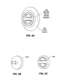
- FIGS. 3A and 3B illustrate an embodiment of a safety shower valve knob.
- FIGS. 4A, 4B, and 4C illustrate the basic components of the shower valve knob.
- a safety door knob 100 overcomes the foregoing drawbacks and addresses the problems described herein.
- the safety knob 100 described herein has been engineered so that any attempt to use it as a hanging platform will fail. None can hang off the safety knob or be wedged within the safety knob without sliding or falling off because all foreseeable hanging points are removed.
- the sentinel event reducing safety knob includes a uniquely-engineered knob that prevents hanging of any material on the knob for use particularly in facilities where there are at risk patients who may attempt suicide, specifically by hanging.
- the safety knob can be used in conjunction with any door that can be hung in any conventional door frame. It is encouraged that the safety knob be used in conjunction with the door described in the above-referenced U.S. Pat. No. 7,024,823.
- FIG. 1 illustrates a preferred embodiment of the sentinel event reducing safety knob 100 .
- the sentinel event reducing safety knob 100 is shown as including a cylinder wedge assembly 110 , such as an outside cylinder wedge assembly 110 _ 0 , and a rose member 120 , such as an outside rose 1200 , suitable for installation at a mounting structure 200 , such as a door.
- the outside rose 1200 has a tapered outer surface 122 .
- the outside rose 120 0 also forms an internal chamber 124 (shown in FIG. 2 ) for receiving the outside cylinder wedge assembly 110 O.
- the outside cylinder wedge assembly 110 _ 0 preferably includes a safety pull wedge 112 and a cylinder member 114 , which can comprise separate units as shown in FIG.
- the safety pull wedge 112 and cylinder member 114 can be coupled via one or more fasteners, such as a screw 17 (shown in FIG. 2 ).
- the cylinder member 114 includes an inner surface 116 that defines an internal opening 118 within the cylinder member 114 .
- an outer surface 113 (shown in FIG. 2 ) of the safety pull wedge 112 is flush with the inner surface 116 of the cylinder member 114 , and, hence, no space is present on the safety knob 100 to operate as a hanging point.
- the safety knob 100 can be activated, such as by rotating and/or translating, to extend and/or retract a locking mechanism 16 . Thereby, when the outside cylinder wedge assembly 110 _ 0 is received within the outer rose 120 0 , the safety knob 100 provides a knob surface that is not suitable for hanging.
- FIG. 2 is an exploded view of the safety knob 100 of FIG. 1 .
- the safety knob 100 includes both the outer rose 120 _ 0 and the outer cylinder wedge assembly 110 _ 0 as well as an inner rose 120 I and an inner cylinder wedge assembly 110 _I.
- the inner rose 120 _ 1 can be provided in the same manner as the outside rose 120 0 described above with reference to FIG. 1 .
- the inner rose 120 _ 1 includes an internal chamber 126 for receiving the inner cylinder wedge assembly 110 _I.
- the inner cylinder wedge assembly 110 _I preferably is provided in the manner set forth above with reference to the outer cylinder wedge assembly 110 _ 0 in FIG. 1 .
- Safety knob 100 can be used with any conventional latching mechanism 16 .
- An illustrative latching mechanism is shown in FIG. 2 .
- the latching mechanism 16 is disposed within the mounting structure 200 and can be activated by the safety knob 100 via conventional hardware 300 .
- the conventional hardware 300 can be installed within an opening 210 formed by the mounting structure 200 .
- the hardware 300 can be disposed within and extend through the opening 210 and includes an outside end region 310 0 for coupling with the outside cylinder wedge assembly 110 _ 0 and an inside end region 310 _ 1 for coupling with the inside cylinder wedge assembly 110 I.
- the outside end region 310 0 of the hardware 300 can pass through an opening (not shown) formed within the outside rose 120 _ 0 and communicating with the internal chamber 124 . Extending within the internal chamber 124 , the outside end region 310 0 can couple with the outside cylinder wedge assembly 110 O. Similarly, the inside end region 310 I of the hardware 300 can pass through an opening 128 formed within the inner rose 120 _ 1 and communicating with the internal chamber 126 . Extending within the internal chamber 126 , the inside end region 310 I can couple with the inside cylinder wedge assembly 110 I.
- the inside cylinder wedge assembly 110 I and the outside cylinder wedge assembly 110 _ 0 each thereby communicate with the hardware 300 and can be activated, such as by rotating and/or translating, to extend and/or retract the locking mechanism 16 .
- the inside cylinder wedge assembly 110 I attaches to the inside end region 310 I.
- the inside end region 310 _I can include an inside knob bushing 7 and an inside needle roller bearing 8 , and can be coupled with the inside cylinder wedge assembly 110 I via one or more fasteners 9 .
- the outside cylinder wedge assembly 110 _ 0 attaches to the outside end region 310 _ 0 .
- the outside end region 310 _ 0 can include an outside knob bushing 27 and a outside needle roller bearing 28 , and can be coupled with the outside cylinder wedge assembly 110 _ 0 via one or more fasteners 29 .
- a spindle 12 passes through the opening 210 , interacting with the latching mechanism 16 , extends into the internal chamber 124 of the outer rose 120 _ 0 , and mates with the outside knob bushing 27 .
- Posts 14 include an internally threaded region 5 for receiving screws 15 . The posts 14 are respectively received within channels 220 formed within the opening 210 and maintain the orientation of the safety knob 100 .
- a safety shower valve handle 240 is shown as a mixing valve handle recessed in a beveled faceplate 242 .
- the mixing valve handle 240 is connected to a control knob 244 by suitable screws 246 .
- the control knob is threaded onto the valve spindle 248 of the water mixing valve 250 which is within the shower wall.
- this suicide prevention shower handle can replace any non-push type shower handle and faceplate. It preferably is made of high impact Corian material which will not rust nor corrode.
- the handle 240 and control knob 244 are securely bolted together with the lip 252 of the faceplate 242 between them as seen in FIG. 3 b . This design prevents the handle from either being pulled apart or pushed in by a patient. It also prevents anything from being slipped behind the handle and used as a hanging point.
Abstract
There is disclosed herein a suicide prevention door handle and shower handle wherein each is designed to eliminate any area or structure that could be used to hold a belt, piece of clothing or the like as an aid in committing suicide by hanging. In each case, the safety knob comprises a tapered rose member or faceplate along with a cylinder wedge assembly or handle.
Description
This application claims the benefit of provisional application Ser. No. 61/082,127, filed Jul. 18, 2008, which application is incorporated herein by reference, and is a continuation of application Ser. No. 12/505,352, filed Jul. 17, 2009, which is incorporated herein by reference. Application Ser. No. 13/452,131, filed Apr. 20, 2012, which is a divisional application of Ser. No. 12/505,352, is also a related application.
The disclosed embodiments relate generally to safety knobs adapted to significantly reduce or eliminate the occurrence of sentinel events and more particularly, but not exclusively, to safety knobs having particular constructions that prevents the physical means for an individual to hang him/herself.
Medical facilities are aware that some of their patient population is at risk of committing suicide, specifically hanging, while being treated in the medical facility. These suicides, referred to in the industry as sentinel events, typically occur either in the bathroom or in the shower stall of the medical facility.
Public use bathrooms typically have bathroom stalls, including a bathroom door and doorknob. The bathroom doors can be used as a platform or location for holding a belt or a piece of clothing to aid in committing suicide by hanging. Various systems for reducing sentinel events have been proposed, such as the sentinel event reduction system set forth in U.S. Pat. No. 7,024,823 entitled Sentinel Event Reduction System, the disclosure of which is incorporated herein by reference in its entirety.
The bathroom doorknob can also be used as a platform or location for holding a belt or a piece of clothing to aid in committing suicide by hanging.
Every bathroom or unit in a medical facility cannot be watched at the same time without enormous staff resources. Therefore, bathrooms, and specifically bathroom doorknobs, provide an area of opportunity for a sentinel event for patients at risk for suicide. Shower knobs also can be a problem.
To date, the problems of sentinel events in bathrooms are typically addressed by removing all bathroom stall hardware, including doors and doorknobs. While this reduces opportunities for sentinel events, it likewise eliminates all privacy that a patient may have.
It should be noted that the Figures are not drawn to scale and that elements of similar structures or functions are generally represented by like reference numerals for illustrative purposes throughout the Figures. It also should be noted that the Figures are only intended to facilitate the description of the disclosed embodiments. The Figures do not illustrate every aspect of the disclosed embodiments and do not limit the scope of the disclosed embodiments.
A safety door knob 100 overcomes the foregoing drawbacks and addresses the problems described herein. The safety knob 100 described herein has been engineered so that any attempt to use it as a hanging platform will fail. Nothing can hang off the safety knob or be wedged within the safety knob without sliding or falling off because all foreseeable hanging points are removed. The sentinel event reducing safety knob includes a uniquely-engineered knob that prevents hanging of any material on the knob for use particularly in facilities where there are at risk patients who may attempt suicide, specifically by hanging.
The safety knob can be used in conjunction with any door that can be hung in any conventional door frame. It is encouraged that the safety knob be used in conjunction with the door described in the above-referenced U.S. Pat. No. 7,024,823.
The outside end region 310 0 of the hardware 300 can pass through an opening (not shown) formed within the outside rose 120_0 and communicating with the internal chamber 124. Extending within the internal chamber 124, the outside end region 310 0 can couple with the outside cylinder wedge assembly 110 O. Similarly, the inside end region 310 I of the hardware 300 can pass through an opening 128 formed within the inner rose 120_1 and communicating with the internal chamber 126. Extending within the internal chamber 126, the inside end region 310 I can couple with the inside cylinder wedge assembly 110 I.
The inside cylinder wedge assembly 110 I and the outside cylinder wedge assembly 110_0 each thereby communicate with the hardware 300 and can be activated, such as by rotating and/or translating, to extend and/or retract the locking mechanism 16.
The inside cylinder wedge assembly 110 I attaches to the inside end region 310 I. The inside end region 310_I can include an inside knob bushing 7 and an inside needle roller bearing 8, and can be coupled with the inside cylinder wedge assembly 110 I via one or more fasteners 9. Similarly, the outside cylinder wedge assembly 110_0 attaches to the outside end region 310_0. The outside end region 310_0 can include an outside knob bushing 27 and a outside needle roller bearing 28, and can be coupled with the outside cylinder wedge assembly 110_0 via one or more fasteners 29.
A spindle 12 passes through the opening 210, interacting with the latching mechanism 16, extends into the internal chamber 124 of the outer rose 120_0, and mates with the outside knob bushing 27. Posts 14 include an internally threaded region 5 for receiving screws 15. The posts 14 are respectively received within channels 220 formed within the opening 210 and maintain the orientation of the safety knob 100.
Turning now to FIGS. 3 and 4 , a safety shower valve handle 240 is shown as a mixing valve handle recessed in a beveled faceplate 242. The mixing valve handle 240 is connected to a control knob 244 by suitable screws 246. The control knob is threaded onto the valve spindle 248 of the water mixing valve 250 which is within the shower wall.
Thus, this suicide prevention shower handle can replace any non-push type shower handle and faceplate. It preferably is made of high impact Corian material which will not rust nor corrode. The handle 240 and control knob 244 are securely bolted together with the lip 252 of the faceplate 242 between them as seen in FIG. 3b . This design prevents the handle from either being pulled apart or pushed in by a patient. It also prevents anything from being slipped behind the handle and used as a hanging point.
The disclosed embodiments are susceptible to various modifications and alternative forms, and specific examples thereof have been shown by way of example in the drawings and are herein described in detail. It should be understood, however, that the disclosed embodiments are not to be limited to the particular forms or methods disclosed, but to the contrary, the disclosed embodiments are to cover all modifications, equivalents, and alternatives.
Claims (3)
1. A safety knob device adapted to activate a shower valve, said safety knob device comprising:
a tubular faceplate comprising a housing adapted to be coupled to a shower valve, said faceplate having a tapered outer surface having an open small diameter end,
a rotatable valve handle having an outer diameter surface which substantially fills said small diameter end, an inner surface of the rotatable valve handle and an interior space of the tubular face plate forming an internal chamber, wherein said rotatable valve handle has an external cavity therein, and a gripping member located in said cavity,
a valve control member located in said internal chamber and adapted to be coupled to a shower valve, and an internal lip located between said valve handle and said valve control member, said internal lip adapted to provide an abutment surface to at least part of the inner surface of the rotatable valve handle;
wherein said safety knob device is arranged in form and shape such that it does not have a surface or point capable of being used as a hanging surface or hanging point.
2. A safety shower valve control device comprising:
a tubular outer body having a proximal end adapted to abut the surface of a shower wall, said outer body having an open distal end, said outer body having a tapered surface extending from said proximal end to said distal end and said distal end having a smaller diameter than said proximal end
a rotatable valve handle having an outer diameter surface which substantially fills the open distal end, an inner surface of the rotatable valve handle and an interior space of the outer body forming an internal chamber;
wherein said rotatable valve handle has an external cavity therein, and a gripping member located in said cavity,
a valve control member located in said internal chamber and adapted to be coupled to a shower valve, and
an internal lip on the interior surface of said outer body extending into said internal chamber, said lip being located between said rotatable valve handle and said valve control member and said rotatable valve handle being coupled to said valve control member, said internal lip adapted to provide an abutment surface to at least part of the inner surface of the rotatable valve handle;
wherein said safety shower control device is arranged in form and shape such that it does not have a surface or point capable of being used as a hanging surface or hanging point.
3. A safety shower valve control device comprising:
a tubular outer member adapted to abut a shower wall, the outer member having a tapered external surface and having an open small diameter end,
a rotatable valve handle member having an outer diameter surface which substantially fills said small diameter end, an inner surface of the rotatable valve handle and an interior space of the tubular outer member forming an internal chamber, said rotatable valve handle adapted to control a shower valve via a valve control member, said valve control member being located in said internal chamber, said valve control member is adapted to be coupled to a shower valve,
said rotatable handle member having an external cavity therein, and a gripping member on said handle member, the gripping member located in said external cavity,
wherein the outer member is adapted to abut a shower wall, and the configuration of the tapered external surface, rotatable handle member, and gripping member is such that said control device does not have a surface or point capable of being used as a hanging surface or hanging point.
Priority Applications (1)
| Application Number | Priority Date | Filing Date | Title |
|---|---|---|---|
| US14/291,425 US9765548B2 (en) | 2008-07-18 | 2014-05-30 | Sentinel event reducing safety knobs |
Applications Claiming Priority (3)
| Application Number | Priority Date | Filing Date | Title |
|---|---|---|---|
| US8212708P | 2008-07-18 | 2008-07-18 | |
| US12/505,352 US8740266B2 (en) | 2008-07-18 | 2009-07-17 | Sentinel event reducing safety knobs |
| US14/291,425 US9765548B2 (en) | 2008-07-18 | 2014-05-30 | Sentinel event reducing safety knobs |
Related Parent Applications (1)
| Application Number | Title | Priority Date | Filing Date |
|---|---|---|---|
| US12/505,352 Continuation US8740266B2 (en) | 2008-07-18 | 2009-07-17 | Sentinel event reducing safety knobs |
Publications (2)
| Publication Number | Publication Date |
|---|---|
| US20140265375A1 US20140265375A1 (en) | 2014-09-18 |
| US9765548B2 true US9765548B2 (en) | 2017-09-19 |
Family
ID=41529659
Family Applications (3)
| Application Number | Title | Priority Date | Filing Date |
|---|---|---|---|
| US12/505,352 Active 2031-01-31 US8740266B2 (en) | 2008-07-18 | 2009-07-17 | Sentinel event reducing safety knobs |
| US13/452,131 Active 2030-01-17 US9267309B2 (en) | 2008-07-18 | 2012-04-20 | Sentinel event reducing safety knobs |
| US14/291,425 Active 2029-12-23 US9765548B2 (en) | 2008-07-18 | 2014-05-30 | Sentinel event reducing safety knobs |
Family Applications Before (2)
| Application Number | Title | Priority Date | Filing Date |
|---|---|---|---|
| US12/505,352 Active 2031-01-31 US8740266B2 (en) | 2008-07-18 | 2009-07-17 | Sentinel event reducing safety knobs |
| US13/452,131 Active 2030-01-17 US9267309B2 (en) | 2008-07-18 | 2012-04-20 | Sentinel event reducing safety knobs |
Country Status (1)
| Country | Link |
|---|---|
| US (3) | US8740266B2 (en) |
Cited By (1)
| Publication number | Priority date | Publication date | Assignee | Title |
|---|---|---|---|---|
| USD891224S1 (en) * | 2018-12-28 | 2020-07-28 | Dezhao Xiang | Lock |
Families Citing this family (15)
| Publication number | Priority date | Publication date | Assignee | Title |
|---|---|---|---|---|
| US8534723B2 (en) * | 2008-10-31 | 2013-09-17 | Securitech Group, Inc. | Conical shank anti-ligature releasable door lever |
| US8430436B2 (en) * | 2009-01-29 | 2013-04-30 | Steven J. Shilts | Anti-ligative doorknob with tri-beveled latchbolt |
| US8584494B2 (en) * | 2010-01-21 | 2013-11-19 | Accurate Lock And Hardware Co., Llc | Anti-ligature door hardware |
| NZ594709A (en) * | 2010-09-09 | 2012-03-30 | Assa Abloy Australia Pty Ltd | Low profile combination lock and latch for sliding cavity door of varying widths |
| US9267310B2 (en) * | 2010-12-20 | 2016-02-23 | Industrilås i NässjöAB | Handle assembly for double-walled door |
| US8646151B2 (en) * | 2011-07-22 | 2014-02-11 | Laurence D. Kopp | Ligature-resistant vertical grab bar |
| TW201416536A (en) | 2012-06-05 | 2014-05-01 | Sargent Mfg Co | Anti-ligature handle and escutcheon for operating a lock |
| US9226730B2 (en) * | 2013-03-15 | 2016-01-05 | Elitechgroup Inc. | Sweat collecting device |
| US9290963B2 (en) * | 2013-03-15 | 2016-03-22 | Securitech Group, Inc. | Door lever and key cylinder lock combination |
| US9585528B2 (en) | 2014-12-19 | 2017-03-07 | Gojo Industries, Inc. | Anti-ligature dispenser |
| US9694505B2 (en) | 2015-02-18 | 2017-07-04 | Schlage Lock Company Llc | Anti-ligature actuators |
| WO2017156526A1 (en) * | 2016-03-11 | 2017-09-14 | Rockwood Manufacturing Company | Restraint resistant handle |
| CA3057904A1 (en) | 2017-05-31 | 2018-12-06 | Sargent Manufacturing Company | Anti-ligature turn piece |
| US11136786B2 (en) | 2018-06-26 | 2021-10-05 | Accurate Lock & Hardware Co. Llc | Confinement room lock |
| GB2618148A (en) * | 2022-04-29 | 2023-11-01 | Anti Ligature Shop Ltd | Anti-ligature keyless access control device |
Citations (14)
| Publication number | Priority date | Publication date | Assignee | Title |
|---|---|---|---|---|
| US2460005A (en) * | 1947-03-11 | 1949-01-25 | Gruen Henry | Plumbing fixture |
| US4313350A (en) * | 1978-05-15 | 1982-02-02 | Kel-Win Manufacturing Co., Inc. | Anti-scald apparatus for a tub and shower single control faucet |
| USD284990S (en) * | 1983-07-02 | 1986-08-05 | Walker Crosweller & Company Limited | Fluid mixing valve for showers or the like |
| US5198826A (en) | 1989-09-22 | 1993-03-30 | Nippon Sheet Glass Co., Ltd. | Wide-band loop antenna with outer and inner loop conductors |
| EP1158603A1 (en) | 2000-05-17 | 2001-11-28 | STMicroelectronics S.A. | Antenna for generation of an electromagnetic field for transponder |
| JP2004173293A (en) | 1995-09-30 | 2004-06-17 | Sony Chem Corp | Antenna for reader/writer |
| US6830193B2 (en) | 2001-11-29 | 2004-12-14 | Matsushita Electric Industrial Co., Ltd. | Non-contact IC card |
| US6971143B2 (en) * | 2002-02-20 | 2005-12-06 | Terumo Cardiovascular Systems Corporation | Magnetic detent for rotatable knob |
| US20070024510A1 (en) | 2005-07-26 | 2007-02-01 | Lear Corporation | System and method for use in wireless communication employing multiple antennas |
| WO2007072381A2 (en) | 2005-12-19 | 2007-06-28 | Nxp B.V. | Radio receiver, radio transmitter, and hearing aid |
| WO2008094383A1 (en) | 2007-01-29 | 2008-08-07 | Fred Bassali | Advanced vehicular universal transmitter using time domain with vehicle location logging system |
| US7741734B2 (en) | 2005-07-12 | 2010-06-22 | Massachusetts Institute Of Technology | Wireless non-radiative energy transfer |
| US7825543B2 (en) | 2005-07-12 | 2010-11-02 | Massachusetts Institute Of Technology | Wireless energy transfer |
| US7899425B2 (en) | 2000-10-03 | 2011-03-01 | Mineral Lassen Llc | Multi-band wireless communication device and method |
Family Cites Families (30)
| Publication number | Priority date | Publication date | Assignee | Title |
|---|---|---|---|---|
| US606724A (en) | 1898-07-05 | Farm-gate | ||
| US1811291A (en) * | 1930-05-02 | 1931-06-23 | Banker Otto | Lock |
| US2606782A (en) * | 1948-01-19 | 1952-08-12 | Samuel A Harkleroad | Door latch |
| US4306468A (en) * | 1979-09-04 | 1981-12-22 | Kohler Co. | Handle assembly |
| AU90017S (en) * | 1983-07-02 | 1985-02-14 | Caradon Mira Ltd | A mixing and control valve |
| US4513350A (en) * | 1984-02-02 | 1985-04-23 | Sprague Electric Company | Monolithic ceramic capacitor and method for manufacturing to predetermined capacity value |
| USD285107S (en) * | 1984-12-04 | 1986-08-12 | Walker Crosweller & Company Limited | Combined control handle and escutcheon for showers or the like |
| USD322839S (en) * | 1988-01-12 | 1991-12-31 | Kohler Co. | Combined handle and escutcheon |
| USD317398S (en) * | 1989-01-13 | 1991-06-11 | A.L. Hansen Manufacturing Company | Rotary lock |
| USD316365S (en) * | 1989-01-13 | 1991-04-23 | A. L. Hansen Manufacturing Company | Rotary lock |
| US5140843A (en) * | 1992-01-27 | 1992-08-25 | Krueger Owen A | Lock conversion mechanism |
| US5190327A (en) * | 1992-07-08 | 1993-03-02 | Lin Jui C | Tubular door lock |
| US5722273A (en) * | 1996-04-08 | 1998-03-03 | Tong Lung Metal Industry Co., Ltd. | Latch bolt operating device |
| US5794871A (en) * | 1997-02-18 | 1998-08-18 | Willetts; Thomas | Removable portable door lock |
| USD421293S (en) * | 1998-12-18 | 2000-02-29 | Daniel Mullenmeister | Combined wall-mount faucet handle head and escutcheon |
| US6840070B1 (en) * | 2003-07-15 | 2005-01-11 | Taiwan Fu Hsing Industrial Co., Ltd. | Door lock |
| US7024823B2 (en) * | 2004-03-12 | 2006-04-11 | The Pines Residential Treatment Center, Inc. | Sentinel event reduction system |
| USD507633S1 (en) * | 2004-05-07 | 2005-07-19 | Brasstech, Inc. | Shower control |
| US7661734B2 (en) * | 2005-03-11 | 2010-02-16 | Kirk Lignell | Door knob cover |
| USD532673S1 (en) * | 2005-03-14 | 2006-11-28 | The Eastern Company | Front portion of a handle and housing assembly |
| USD543434S1 (en) * | 2005-03-23 | 2007-05-29 | The Eastern Company | Front portions of a handle and housing assembly |
| US7273242B2 (en) * | 2005-05-18 | 2007-09-25 | Devany Dawn Godin Flott | Knob assembly for a door |
| US7373694B1 (en) * | 2005-07-22 | 2008-05-20 | Kopp Laurence D | Door handgrip negating suicidal attempt |
| USD584384S1 (en) * | 2007-01-15 | 2009-01-06 | Hansgrohe Ag | Kitchen or bath control |
| US7631655B1 (en) * | 2007-02-20 | 2009-12-15 | Kopp Laurence D | Disassembly method from a water mixing valve of a handle thereof |
| US20100072762A1 (en) * | 2008-09-22 | 2010-03-25 | Marks Usa I, Llc | Lockset |
| US8534723B2 (en) * | 2008-10-31 | 2013-09-17 | Securitech Group, Inc. | Conical shank anti-ligature releasable door lever |
| US8430436B2 (en) * | 2009-01-29 | 2013-04-30 | Steven J. Shilts | Anti-ligative doorknob with tri-beveled latchbolt |
| US8803689B2 (en) * | 2009-08-14 | 2014-08-12 | Securitech Group, Inc. | Over-the-door pressure sensor anti-ligature and alarm system |
| US8584494B2 (en) * | 2010-01-21 | 2013-11-19 | Accurate Lock And Hardware Co., Llc | Anti-ligature door hardware |
-
2009
- 2009-07-17 US US12/505,352 patent/US8740266B2/en active Active
-
2012
- 2012-04-20 US US13/452,131 patent/US9267309B2/en active Active
-
2014
- 2014-05-30 US US14/291,425 patent/US9765548B2/en active Active
Patent Citations (16)
| Publication number | Priority date | Publication date | Assignee | Title |
|---|---|---|---|---|
| US2460005A (en) * | 1947-03-11 | 1949-01-25 | Gruen Henry | Plumbing fixture |
| US4313350A (en) * | 1978-05-15 | 1982-02-02 | Kel-Win Manufacturing Co., Inc. | Anti-scald apparatus for a tub and shower single control faucet |
| USD284990S (en) * | 1983-07-02 | 1986-08-05 | Walker Crosweller & Company Limited | Fluid mixing valve for showers or the like |
| US5198826A (en) | 1989-09-22 | 1993-03-30 | Nippon Sheet Glass Co., Ltd. | Wide-band loop antenna with outer and inner loop conductors |
| JP2004173293A (en) | 1995-09-30 | 2004-06-17 | Sony Chem Corp | Antenna for reader/writer |
| EP1158603A1 (en) | 2000-05-17 | 2001-11-28 | STMicroelectronics S.A. | Antenna for generation of an electromagnetic field for transponder |
| US20020003498A1 (en) | 2000-05-17 | 2002-01-10 | Luc Wuidart | Electromagnetic field generation antenna for a transponder |
| US7023391B2 (en) | 2000-05-17 | 2006-04-04 | Stmicroelectronics S.A. | Electromagnetic field generation antenna for a transponder |
| US7899425B2 (en) | 2000-10-03 | 2011-03-01 | Mineral Lassen Llc | Multi-band wireless communication device and method |
| US6830193B2 (en) | 2001-11-29 | 2004-12-14 | Matsushita Electric Industrial Co., Ltd. | Non-contact IC card |
| US6971143B2 (en) * | 2002-02-20 | 2005-12-06 | Terumo Cardiovascular Systems Corporation | Magnetic detent for rotatable knob |
| US7741734B2 (en) | 2005-07-12 | 2010-06-22 | Massachusetts Institute Of Technology | Wireless non-radiative energy transfer |
| US7825543B2 (en) | 2005-07-12 | 2010-11-02 | Massachusetts Institute Of Technology | Wireless energy transfer |
| US20070024510A1 (en) | 2005-07-26 | 2007-02-01 | Lear Corporation | System and method for use in wireless communication employing multiple antennas |
| WO2007072381A2 (en) | 2005-12-19 | 2007-06-28 | Nxp B.V. | Radio receiver, radio transmitter, and hearing aid |
| WO2008094383A1 (en) | 2007-01-29 | 2008-08-07 | Fred Bassali | Advanced vehicular universal transmitter using time domain with vehicle location logging system |
Non-Patent Citations (2)
| Title |
|---|
| International Search Report and Written Opinion from PCT/US2009/051046, International Search Authority-European Patent Office-dated Oct. 16, 2009. |
| International Search Report and Written Opinion from PCT/US2009/051046, International Search Authority—European Patent Office—dated Oct. 16, 2009. |
Cited By (1)
| Publication number | Priority date | Publication date | Assignee | Title |
|---|---|---|---|---|
| USD891224S1 (en) * | 2018-12-28 | 2020-07-28 | Dezhao Xiang | Lock |
Also Published As
| Publication number | Publication date |
|---|---|
| US20100013248A1 (en) | 2010-01-21 |
| US20120199228A1 (en) | 2012-08-09 |
| US8740266B2 (en) | 2014-06-03 |
| US9267309B2 (en) | 2016-02-23 |
| US20140265375A1 (en) | 2014-09-18 |
Similar Documents
| Publication | Publication Date | Title |
|---|---|---|
| US9765548B2 (en) | Sentinel event reducing safety knobs | |
| US5291760A (en) | Lock for doors | |
| US20220290487A1 (en) | Interior Pre-Hung Hinged Door And Pocket Sliding Security Gate | |
| ES2134723A1 (en) | Arrangement in a lock, especially an electromechanical locking system | |
| US4045065A (en) | Releasable door stop and strike plate assembly for a bidirectional swinging door | |
| US20020067046A1 (en) | Drop lock-outward opening door retaining device | |
| AU2018275570B2 (en) | Anti-ligature turn piece | |
| US4790581A (en) | Safety door latch | |
| US3946460A (en) | Releasable door stop and strike plate assembly for a bidirectional swinging door | |
| US20210332613A1 (en) | Novel Door Latching System Configured For Foot Use | |
| US11136786B2 (en) | Confinement room lock | |
| US6866309B1 (en) | Security bolt latch apparatus and method | |
| US4627651A (en) | Safety locking device for doors | |
| CA1098148A (en) | Portable door securing device | |
| EP3743575A1 (en) | Cubicle having emergency access | |
| US20100102573A1 (en) | Retrofit safety door lock | |
| WO2010068755A1 (en) | Adjustable trim ring for deadbolt locks | |
| EP1476619B1 (en) | Spring latch lock | |
| JP2006265895A (en) | Single sickroom unit | |
| US20090121497A1 (en) | Door security system | |
| GB2105775A (en) | Door-stay | |
| US2574726A (en) | Knob set privacy latch | |
| US11857452B2 (en) | Method and apparatus for restraint anchor | |
| JP3068519U (en) | Simple security lock plate | |
| US20220018160A1 (en) | Locking door handle for single-user washroom and latch therefor |
Legal Events
| Date | Code | Title | Description |
|---|---|---|---|
| STCF | Information on status: patent grant |
Free format text: PATENTED CASE |
|
| MAFP | Maintenance fee payment |
Free format text: PAYMENT OF MAINTENANCE FEE, 4TH YR, SMALL ENTITY (ORIGINAL EVENT CODE: M2551); ENTITY STATUS OF PATENT OWNER: SMALL ENTITY Year of fee payment: 4 |