US9764393B2 - Key blank and carrier adapted for positioning a key blank in a cutter during bit cutting - Google Patents
Key blank and carrier adapted for positioning a key blank in a cutter during bit cutting Download PDFInfo
- Publication number
- US9764393B2 US9764393B2 US15/424,318 US201715424318A US9764393B2 US 9764393 B2 US9764393 B2 US 9764393B2 US 201715424318 A US201715424318 A US 201715424318A US 9764393 B2 US9764393 B2 US 9764393B2
- Authority
- US
- United States
- Prior art keywords
- key blank
- key
- carrier
- blank
- cutter
- Prior art date
- Legal status (The legal status is an assumption and is not a legal conclusion. Google has not performed a legal analysis and makes no representation as to the accuracy of the status listed.)
- Expired - Fee Related
Links
Images


Classifications
-
- B—PERFORMING OPERATIONS; TRANSPORTING
- B23—MACHINE TOOLS; METAL-WORKING NOT OTHERWISE PROVIDED FOR
- B23C—MILLING
- B23C3/00—Milling particular work; Special milling operations; Machines therefor
- B23C3/28—Grooving workpieces
- B23C3/35—Milling grooves in keys
-
- B—PERFORMING OPERATIONS; TRANSPORTING
- B23—MACHINE TOOLS; METAL-WORKING NOT OTHERWISE PROVIDED FOR
- B23C—MILLING
- B23C3/00—Milling particular work; Special milling operations; Machines therefor
- B23C3/28—Grooving workpieces
- B23C3/35—Milling grooves in keys
- B23C3/355—Holders for the template keys
-
- B—PERFORMING OPERATIONS; TRANSPORTING
- B23—MACHINE TOOLS; METAL-WORKING NOT OTHERWISE PROVIDED FOR
- B23C—MILLING
- B23C9/00—Details or accessories so far as specially adapted to milling machines or cutter
-
- B—PERFORMING OPERATIONS; TRANSPORTING
- B23—MACHINE TOOLS; METAL-WORKING NOT OTHERWISE PROVIDED FOR
- B23C—MILLING
- B23C2235/00—Details of milling keys
-
- B—PERFORMING OPERATIONS; TRANSPORTING
- B23—MACHINE TOOLS; METAL-WORKING NOT OTHERWISE PROVIDED FOR
- B23C—MILLING
- B23C2235/00—Details of milling keys
- B23C2235/28—Key blanks
-
- Y—GENERAL TAGGING OF NEW TECHNOLOGICAL DEVELOPMENTS; GENERAL TAGGING OF CROSS-SECTIONAL TECHNOLOGIES SPANNING OVER SEVERAL SECTIONS OF THE IPC; TECHNICAL SUBJECTS COVERED BY FORMER USPC CROSS-REFERENCE ART COLLECTIONS [XRACs] AND DIGESTS
- Y10—TECHNICAL SUBJECTS COVERED BY FORMER USPC
- Y10T—TECHNICAL SUBJECTS COVERED BY FORMER US CLASSIFICATION
- Y10T409/00—Gear cutting, milling, or planing
- Y10T409/30—Milling
- Y10T409/30084—Milling with regulation of operation by templet, card, or other replaceable information supply
- Y10T409/300952—Milling with regulation of operation by templet, card, or other replaceable information supply to cut lock key
- Y10T409/301008—Using templet other than a key
-
- Y—GENERAL TAGGING OF NEW TECHNOLOGICAL DEVELOPMENTS; GENERAL TAGGING OF CROSS-SECTIONAL TECHNOLOGIES SPANNING OVER SEVERAL SECTIONS OF THE IPC; TECHNICAL SUBJECTS COVERED BY FORMER USPC CROSS-REFERENCE ART COLLECTIONS [XRACs] AND DIGESTS
- Y10—TECHNICAL SUBJECTS COVERED BY FORMER USPC
- Y10T—TECHNICAL SUBJECTS COVERED BY FORMER US CLASSIFICATION
- Y10T409/00—Gear cutting, milling, or planing
- Y10T409/30—Milling
- Y10T409/30084—Milling with regulation of operation by templet, card, or other replaceable information supply
- Y10T409/300952—Milling with regulation of operation by templet, card, or other replaceable information supply to cut lock key
- Y10T409/301064—Complete cycle
-
- Y—GENERAL TAGGING OF NEW TECHNOLOGICAL DEVELOPMENTS; GENERAL TAGGING OF CROSS-SECTIONAL TECHNOLOGIES SPANNING OVER SEVERAL SECTIONS OF THE IPC; TECHNICAL SUBJECTS COVERED BY FORMER USPC CROSS-REFERENCE ART COLLECTIONS [XRACs] AND DIGESTS
- Y10—TECHNICAL SUBJECTS COVERED BY FORMER USPC
- Y10T—TECHNICAL SUBJECTS COVERED BY FORMER US CLASSIFICATION
- Y10T409/00—Gear cutting, milling, or planing
- Y10T409/50—Planing
- Y10T409/50082—Process
-
- Y—GENERAL TAGGING OF NEW TECHNOLOGICAL DEVELOPMENTS; GENERAL TAGGING OF CROSS-SECTIONAL TECHNOLOGIES SPANNING OVER SEVERAL SECTIONS OF THE IPC; TECHNICAL SUBJECTS COVERED BY FORMER USPC CROSS-REFERENCE ART COLLECTIONS [XRACs] AND DIGESTS
- Y10—TECHNICAL SUBJECTS COVERED BY FORMER USPC
- Y10T—TECHNICAL SUBJECTS COVERED BY FORMER US CLASSIFICATION
- Y10T409/00—Gear cutting, milling, or planing
- Y10T409/50—Planing
- Y10T409/501476—Means to remove flash or burr
Definitions
- aspects of this document relate generally to key duplication. More specific implementations involve individual carriers for key blanks which may be used as display and/or product dispensing packaging that aligns and positions a key blank in a key blank cutter without the need for a separate clamp for each key type and model.
- a master key for opening a lock when a master key for opening a lock is duplicated, it is conventionally duplicated by first classifying the master key to be able to identify an appropriate key blank into which to cut a bit pattern for the duplicate key, selecting the appropriate key blank to match the master key, placing the selected key blank in a key cutter, and cutting the bit pattern from the master key into a blade of the key blank.
- Conventional systems have required the operation skills of a trained worker to properly select the appropriate key blank.
- An example of an elaborate system used to assist a trained worker in selecting an appropriate key blank and appropriately positioning and clamping the appropriate key blank and master key for cutting is disclosed in U.S. Pat. No.
- a recent key duplication system described in International Application Number PCT/US2007/024522 to Freeman, et al. titled “Fully Automatic Key Duplicating Machine with Automatic Key Model Identification System” sought to reduce the need for the operation skills of a trained worker by automatically identifying master keys and automatically cutting and dispensing a duplicate key from a limited selection of keys within the key duplication system.
- Another recent key duplication system described in U.S. Pat. No. 7,890,878 to Bass et al., titled “Object Identification System,” discloses a system that identifies an appropriate key blank by flashing a light adjacent the appropriate key blank on a product display next to a key blank cutter so that the user or a trained worker can select the appropriate key for insertion into the key blank cutter.
- Other systems require changing of clamps for different key blank models to enable secure positional clamping of the different key blank models in relation to the cutting wheel of a key blank cutter.
- a key blank cutting carrier adapted for mechanical interface with a key blank cutter may comprise a key blank carrier, a key blank recess within the carrier, the recess comprising at least two walls and sized and shaped to securely receive at least a portion of a key blank within the recess, and at least one key blank cutter alignment feature extending from a surface of the carrier at an angle of at least 20 degrees relative to the surface, the at least one key blank cutter alignment feature positioned on the carrier to mechanically engage a portion of a key blank cutter into which a portion of the key blank carrier is placed and align the key blank with the key blank cutter.
- the key blank cutter alignment feature may extend lengthwise along at least a portion of a first wall of the at least two walls of the key blank recess.
- the at least one key blank cutter alignment feature may comprise a first side extending from the carrier at the angle of at least 20 degrees converging toward a second side extending from the carrier at an angle of about 90 degrees.
- the key blank cutter alignment feature may be integrally forced with the key blank carrier.
- the key blank carrier may have an opening along a first edge thereof.
- the opening may comprise a beveled edge extending for at least a portion of the opening.
- the opening may be V-shaped.
- the carrier may comprise an elongated sleeve defining at least a portion of the key blank recess, wherein the sleeve further comprises a tip end and a head end, the head end comprising a substantially planar surface, the tip end being at least partly formed by the at least two walls and at least two additional walls, wherein the tip end at least two walls and at least two additional walls defining key blade carrier front and back sides and key blade carrier hit and spine sides respectively, the key blade carrier front side comprising at least one aperture extending through the key blade carrier front side along an edge of the front side bordering the key blade carrier spine side.
- the at least one aperture extending through the key blade carrier front side may comprise at least two apertures extending through the key blade carrier front side along the edge of the front side bordering the key blade carrier spine side.
- the carrier may comprise an elongated sleeve defining at least a portion of the key blank recess, wherein the sleeve further comprises a tip end and a head end, the head end comprising a substantially planar surface, the tip end being at least partly formed by the at least two walls and at least two additional walls, wherein the tip end at least two walls and at least two additional walls defining key blade carrier front and back sides and key blade carrier bit and spine sides respectively, the key blade carrier front side comprising at least one aperture extending through the key blade carrier front side along an edge of the front side on the key blade carrier bit side.
- the key blank carrier may comprise a key blank positioned within the recess in direct contact with the at least two walls.
- the carrier may comprise an elongated sleeve defining at least a portion of the key blank recess, wherein the sleeve further comprises a tip end and a head end, the head end comprising a substantially planar surface, the tip end being at least partly formed by the at least two walls and at least two additional walls, wherein the tip end at least two walls and at least two additional walls defining key blade carrier front and back sides and key blade carrier bit and spine sides respectively, the key blade carrier front side comprising at least one aperture extending through the key blade carrier front side along an edge of the front side on the key blade carrier bit side, the key blade carrier bit side further comprises a shoulder band adjacent to the head end between the head end and the at least one aperture, the shoulder band extending from the front side of the key blade carrier to the back side of the key blade carrier.
- a key blank cutting carrier adapted for mechanical interface with a key blank cutter may comprise a key blank carrier body, a key blank recess within the key blank carrier body, the recess defined by at least two walls and sized and shaped to securely receive at least a portion of a key blank within the recess, at least one key blank cutter alignment feature coupled to the carrier body and positioned on the carrier body to mechanically engage a portion of a key blank cutter into which a portion of the key blank carrier is placed, and a key blank burr removal opening in a first edge of the carrier body.
- the key blank burr removal opening may comprise a beveled edge.
- the key blank burr removal opening may comprise a V-shaped opening.
- the key blank carrier body may further comprise a substantially planar surface, and the first edge of the carrier body forming a first edge of the substantially planar surface.
- the carrier may comprise an elongated sleeve defining at least a portion of the key blank recess, wherein the sleeve further comprises a tip end and a head end, the head end comprising a substantially planar surface, the tip end being at least partly formed by the at least two walls and at least two additional walls, wherein the tip end at least two walls and at least two additional walls defining key blade carrier front and back sides and key blade carrier bit and spine sides respectively, the key blade carrier front side comprising at least one aperture extending through the key blade carrier front side along an edge of the front side bordering the key blade carrier spine side.
- the at least one aperture may extend through the key blade carrier front side comprises at least two apertures extending through the key blade carrier front side along the edge of the front side bordering the key blade carrier spine side.
- the carrier may comprise an elongated sleeve defining at least a portion of the key blank recess, wherein the sleeve further comprises a tip end and a head end, the head end comprising a substantially planar surface, the tip end being at least partly formed by the at least two walls and at least two additional walls, wherein the tip end at least two walls and at least two additional walls defining key blade carrier front and back sides and key blade carrier bit and spine sides respectively, the key blade carrier front side comprising at least one aperture extending through the key blade carrier front side along an edge of the front side on the key blade carrier bit side, the key blade carrier bit side further comprises a shoulder band adjacent to the head end between the head end and the at least one aperture, the shoulder band extending from the front side of the key blade carrier to the back side of the key blade carrier.
- a method of cutting a key blank to form a duplicate key may comprise inserting a key blank positioned in a key blank carrier into an opening in a key blank cutter, cutting a key bit pattern of a master key into the key blank with a key blank cutting wheel, removing the cut key blank and key blank carrier from the key blank cutter, separating the cut key blank from the key blank carrier, and moving a blade of the cut key blank along a key blank burr removal opening on the key blank carrier until at least one burr is removed from the blade of the cut key blank.
- FIG. 1 is a block diagram of a specific key duplication process embodiment
- FIGS. 2A and 2B are a front views of key blank carriers illustrating a first set of features
- FIG. 3A is a side view of a key blank carrier with a retaining clip in a flexed position
- FIG. 3B is a side view of a key blank carrier with a retaining clip in a rest position
- FIG. 3C is a tip end view of the retaining clip of FIG. 3A ;
- FIG. 3D is a back side view of the retaining clip of FIG. 3D ;
- FIG. 4 is a block diagram of a specific key cutting process embodiment
- FIGS. 5A-5E are cut away views of a key blank cutter during a key blank cutting process
- FIG. 6 is a front view of a key blank carrier illustrating additional features
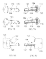
- FIGS. 7A and 7B are front and back side views of key blank carriers for two different key models illustrating a key blank security feature
- FIGS. 8A and 8B are front and back side views of a key blank carrier illustrating a portion of the key blade sleeve removed in combination with a key blank security feature;
- FIGS. 9A and 9B are front and back side views of key blank carriers for two different key models illustrating a portion of the key blade sleeve removed in combination with a key blank security feature and a key blank head channel;
- FIG. 9C are distal tip end views of the key blank carriers of FIG. 9A ;
- FIG. 9D is a representation of a shape formed by the end view of the distal end tip view footprint caused by from the sleeve tip and alignment ridges;
- FIGS. 10A and 10B are distal tip end views of two different key carriers
- FIGS. 11A and 11B are front and back side views of key blank carriers for two different key models illustrating a different sized flag in combination with a key blank security feature;
- FIG. 12 is a front perspective view of a key blank carrier comprising a hinged front side
- FIG. 13 is a front perspective view of a key blank carrier without a front side
- FIG. 14 is a front view of a side-mount key blank carrier
- FIGS. 15A-15G are views of a key blank with an oversized head and a key blank carrier with a step between the substantially planar flag and the key blank recess;
- FIGS. 16A-16C are front, side and perspective views of a key blank carrier comprising a key blank recess configured to receive a key blank head;
- FIGS. 17A-17C are front, side and perspective views of a key blank carrier like that of FIGS. 16A-16C but comprising additional alignment features;
- FIGS. 18A-18C are front, side and perspective views of a key blank with an alignment feature on the key tip.
- FIG. 19A-19C are front, side and perspective views of a key blank with an alignment feature on the key head.
- FIG. 20 is a front perspective view of a key blank carrier with a key blank burr removal opening.
- FIG. 21 is a tip end view of the key blank carrier of FIG. 20 .
- FIG. 22 is a back side view of the key blank carrier of FIG. 20 .
- FIG. 23 illustrates tip end views of different individual key blank carriers in a system of key blank carriers with a uniform sleeve thickness.
- key blanks, carriers and implementing components may comprise any shape, size, style, type, model, version, measurement, concentration, material, quantity, and/or the like as is known in the art for such key blanks, carriers and implementing components, consistent with the intended operation and use of a key blank or carrier.
- Implementations of key blank carriers or key blanks with a standard reference features may include alignment features on a key blank head, key blank tip, a key blank carrier coupled to a key blank sleeve and/or a key blank sleeve, and any feature directly attached to any portion of the key that may be used for referencing in the key duplication system, or any combination of these.
- Alignment of a key blank, and the alignment features on a key blank carrier or key blank comprises alignment in the spatial x-y-z sense and may also comprise orientational or rotational alignment.
- the standard reference features on a key blank carrier may allow any key blank brand model to interface with the machine so as to consistently align each key, regardless of its make and model, in a proper position in relation to a key blank cutter and in a proper orientation for cutting in a universally configured key blank clamp that is adapted to the standard reference features and clamped to reduce the movement of the key blank during duplication cutting.
- the key blank may be vended from an associated key blank vending machine in communication with the master key identifier.
- other additional methods and/or system components may be used as well.
- the specific identification process used to identify the master key make, model and bit pattern for selection of an appropriate key blank is not crucial to the present disclosure and any method may be used in combination with the present disclosure.
- the specific cutting and checkout processes are also not crucial to the present disclosure and any discussion of them is provided as an example for clarity of discussion and is not intended as a limitation for use of the key blank carriers discussed herein.
- the present disclosure relates to a carrier associated with the key blank and may be used for displaying or dispensing the key blank in addition to its use as a fixture for holding the key during the cutting process and even as the key blank packaging at checkout.
- a carrier or packaging its use with standard external features enables a key blank cutter to have a standard key blank receiving aperture and standard key blank carrier clamping components despite the large variations between various key blanks, enabling the key blank cutter to have a standardized key blank clamp to cut all side-cut key blanks using the same key blank clamp rather than the conventional systems which required a plurality of separate clamp units.
- FIGS. 2A and 2B illustrate a particular implementation of a key blank carrier 2 , 4 , adapted to two very different key blanks 6 , 8 .
- the key blank carriers 2 , 4 each have common features and characteristics to enable use of the two key blank carriers 2 , 4 in the same key cutter (see example of FIG. 4 ).
- the key blank carriers 2 , 4 each comprise a key blank recess 10 at least partially within a key blade sleeve 12 , 14 .
- the key blank carrier 2 , 4 of FIGS. 2A and 2B each comprises a tip end 28 having a width CWt 1 , CWt 2 , and a head end 30 having a width CWh 1 , CWh 2 , and a total length CL 1 , CL 2 .
- the head end 30 comprises a substantially planar carrier flag 15 extends from the key blade sleeve 12 , 14 toward the key blank 6 , 8 head.
- the substantially planar carrier flag 15 comprises a key blank head channel 16 , 18 adapted for the particular key blank 6 , 8 intended for use in the key blank carrier 2 , 4 .
- the channels 16 , 18 should be sized, in combination with the other features of the respective key blank carriers 2 , 4 to contact the key blank 6 , 8 heads and retain the key blanks 6 , 8 into their designed carrier sufficient for holding the key blank in a desired position in relation to the key blank carrier 2 , 4 for cutting in an appropriately configured cutting system.
- the key blank head channels 16 , 18 of these particular embodiments illustrate a channel width W defined by two opposing channels 16 , 18 , each with a depth D
- only one channel 16 , 18 may be used if the key blank 6 , 8 is otherwise retained into the carrier 2 , 4 sufficient for cutting.
- Openings to the channels 16 , 18 of these embodiments comprise a flared wall 20 to assist in insertion of the respective key blanks 6 , 8 .
- Particular embodiments may comprise a security feature, such as a retaining clip 22 positioned adjacent to the key blank head channel 16 , 18 .
- the retaining clip 22 when used, is configured to flex rearward ( FIG. 3A ) of the carrier flag 15 from a rest position ( FIG. 3B ) aligned with the carrier flag 15 so that when the key blank 6 , 8 is fed into the key blank recess 10 through the key blank channel 16 , 18 , the retaining clip 22 flexes rearward to allow the key blank 6 , 8 to pass into the key blank channel 16 , 18 and return back to its rest position when the key blank 6 , 8 head has passed.
- the retaining clip 22 secures the key blank 6 , 8 into the key blank recess 10 when the key blank is in a fully inserted position in the recess ( FIGS. 2A and 2B ).
- Reference numbers and/or letters 24 may be included on the key blank carrier 2 , 4 to indicate the key blank packaged in the carrier or the key blank for which the carrier was configured.
- a dispensing or display aperture 26 may be included at or near an edge of the carrier flag 15 . Use of a reentrant opening aperture 26 such as that illustrated in FIGS. 2A and 2B provides particular advantage with a rigid dispensing system support developed herewith but disclosed in more detail in a separate application.
- the tip end 28 of the key blank carrier 2 , 4 comprises at least a portion of the key blank recess 10 embodied as a key blank sleeve 28 .
- the key blank recess 10 comprises at least two walls 32 , 34 , 36 , 38 ( FIG. 3C ) that when a key blank 6 , 8 is inserted into the recess 10 contacts at least two sides of the key blank 6 , 8 .
- the key blank recess 10 embodied as a key blank sleeve 28 contacts at least two sides of the key blank 6 , 8 blade.
- the overall key blank carrier 2 , 4 comprises a depth CD.
- the carrier is designed to be disposable and/or sold with the particular key blank which it holds, and because the carrier itself does not require any additional clamps or moving parts, it can be made small.
- the carrier width CWh 1 , CWh 2 is not more than 3 inches at the carrier flag
- the carrier width CWt 1 , CWt 2 is not more, than 3/4 inch at the sleeve
- the carrier depth CD is not more than 1/2 inch
- the carrier length CL 1 , CL 2 is not more than 4 inches.
- Particular embodiments are adapted to specific key models and will be configured relative to their respective sizes.
- a key blank carrier has a carrier width CWh 1 , CWh 2 of approximately 2 inches at the carrier flag and a carrier width CWt 1 , CWt 2 of approximately 1/2 inch at the sleeve, approximately 3/8 inch carrier depth CD and approximately a 3 inch carrier length CL 1 , CL 2 .
- the key blank carrier walls 32 , 34 , 36 , 38 each comprise a thickness of 3/8 inch or less, and in particular embodiments, a thickness of 1 ⁇ 4 inch or less so that the key blank carrier walls 32 , 34 , 36 , 38 do not extend a significant distance from the key blank in relation to the thickness of the key blank.
- the inside of the key blank recess is configured and adapted to closely hold the particular key blank 6 , 8 for which the corresponding carrier 2 , 4 is designed. This may be accomplished in many different ways, but one particular way is to include one or more ridges 35 in at least a portion of the key blank carrier sleeve 12 to mate with a keyway (groove in the key blade) of the key blank.
- the carrier 2 , 4 ultimately is inserted into a key cutter adapted to engage the carrier 2 , 4 which positions the key blank blade for accurate cutting by the key blank cutter. If the key blank 6 , 8 is not positionally secured within the carrier 2 , 4 when the carrier 2 , 4 is inserted into the key blank cutter, the key blank may not be accurately positioned by the key blank carrier 2 , 4 or accurately cut by the key blank cutter.
- the key blank recess may comprise the key head channel with or without a key blade sleeve.
- the key blank carrier 2 , 4 may be a disposable plastic carrier which is used for one or more of displaying the key blank on a display or in a vending machine, dispensing the key blank from a vending machine, verifying that the selected key blank is correctly selected, positioning and holding the key blank in the key blank cutter, and bearing the check-out code 52 (such as a bar code or alphanumeric code) ( FIG. 3D ) with which the user can pay for the key blank.
- the check-out code 52 such as a bar code or alphanumeric code
- the vending system may dispense a separate key blank carrier that is not mated with the key blank when dispensing the key blank.
- the user may be instructed to insert the key blank into the carrier before inserting the carrier and key blank into a key blank cutter.
- a key blank carrier whether dispensed separately or previously incorporated with the key blank, may comprise a sleeve and/or a head cap or other alignment fixture that removably couples to the key blank.
- ridges on an inside surface of the key blank carrier may be positioned and configured to engage grooves on the key blade to more securely hold the key blank within the carrier.
- a portion of the walls 32 , 34 , 36 , 38 may be removed or recessed to expose all or a portion of the key blade for cutting through an aperture in a carrier wall, which aperture may be configured as a recess on a side of at least one of the carrier walls as illustrated in FIGS. 2A, 2B .
- the key blade may not be exposed and the key may be cut through the carrier 2 , 4 .
- FIGS. 2A, 2B and 3C comprise a key blade bit side wall 32 (corresponding to a side of the key blank blade into which the key bit pattern is cut), key blade spine side wall 34 (corresponding to a side of the key blank blade called the spine), a front side wall 36 and a back side wall 38 .
- the portion of at least the front and bit sides is missing or recessed between the head end 30 and a distal end 40 of the tip end 28 that exposes a majority of a bit edge 7 , 9 of the key blank 6 , 8 when the key blank 6 , 8 is in its fully inserted position in the key blank carrier 2 , 4 ( FIGS. 2A and 2B ).
- Standard carrier features and characteristics may be included on a plurality of carriers designed for a variety of key blank makes and models. For example, although the characteristics of the key blank recess will be different for different key blanks to receive and hold the key blanks, external characteristics of the carriers may be made the same so that the carriers all interact with a standard key blank cutter aperture to receive and position the key blank blades of all key blanks within an appropriately configured carrier in a correct location in relation to a cutting wheel of the cutter. Variations in key blanks require that for an accurate cut, the key blank must be positioned accurately within a three-dimensional space adjacent to the cutting wheel. By adapting relative carrier dimensions, all key blanks may be accurately positioned by a corresponding appropriately configured carrier in a key blank cutter.
- the key blank recess may be positioned more toward the spine side 34 or to the bit side 32 , more toward the front side 36 or toward the back side 38 (in any implementation or embodiment, whether configured as a key blank blade sleeve or simply as a key head recess), and may be positioned more toward the distal end 40 or toward the head end 30 of the carrier (relationally speaking to enable the key blade to be positioned farther or less into the cutter).
- a key blank cutter alignment feature may be included on an outer surface of the carrier 2 , 4 .
- 2A, 2B and 3C illustrate ridges 42 , 44
- other key blank cutter alignment features may be used such as, by non-limiting example, ridges, grooves, shaped cutter cross-sections, clips and the like to mate with a correspondingly shaped portion of the key blank cutter aperture to properly align the key blank carrier within the cutter for accurately cutting the particular key blank for which the key blank carrier was designed.
- a particular implementation of an alignment feature may comprise a first ridge 42 on an outer surface of the sleeve 12 , 14 extending lengthwise along a portion of the sleeve 12 , 14 .
- the first ridge 42 extends along a border of the key blade sleeve 12 , 14 adjacent the key blank spine side 34 .
- Inclusion of the ridge along the border adjacent the spine side 34 allows for stable support for the ridge 42 while allowing the front side 36 of the sleeve 12 , 14 to flex enough for a key blank clamp of a key blank cutting system to clamp the key blank carrier 2 , 4 with sufficient force to flex the carrier 2 , 4 outer surface of the sleeve 12 , 14 toward the key blank 6 , 8 , causing the sleeve 12 , 14 to more securely grip the key blank 6 , 8 within the sleeve 12 , 14 through the carrier 2 , 4 prior to cutting.
- Other embodiments may include a ridge in other locations on the sleeve 12 , 14 or head flag 15 .
- a ridge 42 on the front side 36 of the sleeve 12 , 14 creates an asymmetrical shape for an end view of the tip end 28 of the sleeve 12 , 14 that inserts into a key blank cutter.
- the end view of the tip end 28 for particular embodiments may be made unique enough to allow insertion of the tip end 28 in only one orientation, that unique shape being asymmetrical for all but not more than one cross-section of the shape. Having a shape that is asymmetrical for all but not more than one cross-section of the shape ensures that the insertion orientation of the key blank carrier is always known.
- both sides of the key may be cut with mirrored patterns. In this case, it is not important to cutting the key blank whether a first or a second key blade edge is facing the cutting wheel, but only that it is correctly positioned within the key blank cutter aperture in relation to the cutting wheel and oriented correctly in relation to the wheel with the first or second key blade edge facing the wheel. Nevertheless, it may be important which edge of the key blank carrier is facing up or down for implementations involving an identifying bar code sticker ( FIG.
- a second ridge 44 may be included on a second side, such as the back side 38 , of the sleeve 12 , 14 to further assist in alignment.
- an aperture or slit 48 may be included in a front 36 or back 38 side of the sleeve 12 , 14 .
- the slit 48 is included along a border of the bit side 32 of the carrier 2 , 4 sleeve 12 , 14 . Addition of the slit 48 immediately adjacent to the bit side 32 of the sleeve 12 , 14 provides two key advantages. First, the slit allows the front side 36 of the sleeve 12 , 14 to be less rigid and to flex when a key blank cutter clamp presses against the outer surface of the sleeve 12 , 14 .
- the slit 48 positioned immediately adjacent to the bit side 32 of the sleeve 12 permits the bit side 32 of the sleeve 12 to flex outward slightly away from the bit edge of the key blank blade when a key blank 6 , 8 is inserted into the sleeve 12 .
- the key blank 6 bit edge can contact the bit side wall 32 . Even if manufacturing tolerances are off for the particular key blank 6 or the carrier 4 , the carrier 4 can adjust to the width of the key blade and still cause the carrier to press the key blade against the spine side wall 34 of the sleeve 12 .
- the distal end 40 of the carrier 2 , 4 may be made a known length from where a shoulder 50 of the key blank 6 , 8 will sit in the carrier 2 , 4 for the particular key blank 6 , 8 so that the key blank cutter can sense that the key blank has been fully inserted into the cutter and is ready to be clamped for cutting.
- the known length may be longer than the key blade for the particular key blank for which the carrier 2 , 4 is designed.
- the relative positioning of the key blank shoulder 50 can be accurately known for accurate positioning in the cutter and accurate key blank cutting of the key bit pattern in relation to the key blank shoulder 50 .
- a leading edge of the ridge 42 may be tapered toward the outer surface of the sleeve 12 , 14 as the ridge 42 nears the distal end 40 of the key sleeve 12 , 14 . Tapering toward the outer surface allows the shape of the end view of the sleeve 12 , 14 to more easily insert into a mating shape on the key cutter.
- a divot 46 FIGS. 3B and 3C ) may be included in one or more ridges 42 , 44 on the key sleeve 12 , 14 .
- a divot 46 allows for a reference point on the key sleeve that can be used by a key blank cutter to engage the key blank carrier 24 (see FIG. 5D and related discussion).
- the divot 46 in the carrier 2 , 4 is positioned to engage a spring biased clip in the cutter when a user inserts the carrier 2 , 4 into the cutter and gives the user a tactile response to know that the carrier 2 , 4 is fully inserted.
- 3B and 3C include the divot 46 in one or more ridges 42 , 44 , a similarly functioning reference point on the carrier 2 , 4 may be made at other places on the carrier 2 , 4 in other embodiments and implementations.
- the distal end 40 of the sleeve 12 , 14 may have one or more tapered outer surfaces to simplify insertion of the sleeve 12 , 14 into an aperture on the key blank cutter.
- a carrier such as that illustrated in FIGS. 2A and 2B , may comprise a reference indicator on the carrier 2 , 4 indicating to the user which side is up and in which direction the user should insert the carrier 2 , 4 into a key blank cutter.
- the reference indicator 56 may comprise an arrow placed on the sleeve 12 , 14 .
- the reference indicator 56 may be an aperture through the front side wall 36 of the sleeve.
- a reference indicator such as an aperture through a wall of the sleeve 12 , 14 or other reference indicator on the carrier 2 , 4 may be included on the carrier 2 , 4 that functions as a reference point for the key blank cutter to ensure the key blank carrier 2 , 4 is fully inserted into the key blank cutter. This may be confirmed through the portion of the key blank carrier 2 , 4 in many different ways, such as, without limitation, engaging a switch within the cutter, blocking a light beam, or allowing a light beam.
- a carrier such as that illustrated by FIG. 3D
- RFID radio frequency identification
- inclusion of a bar code sticker 52 on a back surface of the carrier 2 , 4 of FIG. 2A or 2B over the retaining clip 22 may be used to restrict flexing of the retaining clip to further restrict key blank removal from the carrier 2 without damaging the sticker 52 .
- the bar code on the sticker 52 may also be used by the key blank cutter to confirm that the particular key blank being cut is an appropriate key blank for the master key identified by the system.
- the bar code on the sticker 52 may also be used for product checkout at a cash register to allow the user to pay for the duplicate key after it is cut.
- An RFID tag 54 may be used for any of these uses as well, but also has an advantage of being trackable from a distance.
- Particular implementations comprise an RFID tag on or in the carrier, and in particular embodiments, the RFID tag is included on or in the key sleeve.
- FIG. 4 illustrates an example of a detailed cutting process.
- a bit pattern reading device outputs the master key bit pattern to the key blank cutter.
- the reading device may send the bit pattern to the cutting portion through electrical signals, mechanical movements, or other information transfer methods.
- the identification process may output the key blank type to the user, may simply dispense a correctly configured key blank or may allow the user to select from a variety of correctly configured key blanks to match the identified master key.
- Particular embodiments of the output may be in the form of a color code, an alphanumeric code, or other identifiable method so the user may select the correct key blank from the matching code on the carrier.
- the key blanks may be stored in a rack or dispensing machine.
- a reference indicator such as on a key blade sleeve tip or key blade head clip indicates that the key blank and carrier are fully inserted into the cutter.
- the key blank may be verified to ensure that the correct key blank was selected.
- the verification step may occur prior, during, or after insertion into the cutter.
- the step may occur automatically or the user may be prompted to complete this step.
- Particular embodiments may include a prompting to the user to scan the key sleeve in a barcode reader or the system automatically reading the key bar code or RFID tag code upon insertion by the user. If the key blank is wrong, the machine may prompt the user to select the correct key, disable the machining capabilities of the machine, or by another method inhibit the equivocal duplication of a key blank.
- the cutting portion of the key may clamp the key and the cutting wheel duplicates the bit pattern into the blade of the key blank. If the key is a double sided key, the machine may automatically flip the key, prompt the user to turn the key over, or by another method cut two sides of the key.
- FIGS. 5A-5E illustrate various cross-sectional views of an example of a key blank cutter 90 with a cutting wheel 92 , the key blank cutter 90 adapted for cutting a key blank 100 in a key blank carrier 102 embodied as a key sleeve.
- FIGS. 5A-5C illustrate a top down cross-sectional view of the cutter 90 with the key blank 100 in its carrier 102 .
- FIG. 5A illustrates the key blank 100 in its carrier upon removal from the cutter 90 .
- the cutting wheel 92 may be disengaged and the key entry 94 opened prior to insertion of the carrier 102 .
- One or more alignment features 104 on the carrier 102 and a tip end view shape of the carrier 102 ensure that the key blank 100 is properly positioned within the cutter 90 in relation to the cutting wheel 92 including that the key blade bit edge is facing toward the cutting wheel 92 ( FIG. 5B ).
- a carrier tip sensor 96 senses that the carrier 102 is fully inserted and the carrier 102 and key blank 100 are clamped in place.
- the cutting wheel 92 contacts the key blade (see FIG. 5C ) to duplicate the appropriate bit pattern as determined by the identification process.
- FIG. 5E One or more alignment features 104 on the carrier 102 and a tip end view shape of the carrier 102
- FIG. 5D illustrates a side cross-sectional view of the embodiment of FIG. 5A , illustrating clamps extending along a length of the key blank 100 blade.
- the tip sensor 96 is embodied as a hook shaped cam that interfaces with a sensor contained in the cam housing 95 and a divot 106 in the key blank carrier.
- the one or more clamps press at least a portion of the key blank blade, and thereby may immobilize the key blank during cutting.
- FIG. 5E illustrates a cross-sectional sleeve distal end view of the clamp 98 and key blank blade 105 which is orthogonal to the view of FIG. 5D .
- the one or more alignment features 104 on the carrier 102 are shown to interface with corresponding features 106 on the carrier aperture and in this embodiment even with the one or more clamps 98 themselves. Interface between the one or more alignment features 104 and corresponding features on the one or more clamps 98 themselves further provides stability for the key blank 100 and its carrier 102 during cutting.
- the one or more clamps 98 may or may not directly contact the key blank blade 105 during the cutting process and may clamp the key blank 100 through the carrier 102 or through a combination of direct contact with the key blank 100 and through the carrier 102 .
- secondary processes may be employed to further prepare the key for use, such as removing extra features from the key such as extended tips, knobs, or ridges.
- the key may also be deburred by passing the cutting wheel across the key bits a second time to clean them up and smooth them out.
- the key duplication system may have a verification method for determining if the now duplicated key matches the master key. The verification may occur within the cutting area of the cutter, or in a separate location.
- FIG. 6 illustrates another embodiment of a carrier 110 comprising many of the similar features to the particular embodiments described with reference to FIGS. 2 and 3 and description of those Figures should apply to the particular embodiment of FIG. 6 with the exception of the two elements discussed here.
- an aperture 112 is included through the substantially planar key head surface that is sized and shaped to mate with the cross-sectional profile of the master key matching the key blank for which the carrier is designed. Inclusion of a mating aperture similar to a lock keyway opening, allows the user to further confirm that the key blank the user is about to cut for the master key matches the master key.
- a display aperture 114 is also included, similar to the display aperture 26 of FIGS.
- the display aperture 114 is not a reentrant opening aperture. Instead, it is simply an aperture that permits a display rod to be inserted there through for displaying the product prior to sale. Either aperture type may be used on any of the embodiments disclosed herein depending upon the needs of a particular product display or vending unit.
- FIGS. 7A and 7B illustrate, respectively, another embodiment of a key blank recess implemented as a key blank blade sleeve.
- FIG. 7A shows a perspective view of a front side of each of two key blanks 116 , 118 from different manufacturers within key blank carriers 120 , 122 designed for those specific key blanks
- FIG. 7B shows a perspective view of a back side of the key blanks 116 , 118 within the key blank carriers 120 , 122 .
- Many of the same features discussed in relation to the carriers and key blanks discussed in relation to FIGS. 2 and 3 are shown in the embodiments of FIGS.
- a security feature 124 in FIGS. 7A and 7B embodied as a retaining clip 124 , may be included on the carrier to physically engage with a corresponding feature on the key blank 116 , 118 .
- the retaining clip 124 allows the key blank to be inserted into the carrier sleeve, but once the clip engages with an additional notch 126 , cut out from a side of the key blank 116 , 118 , the key blank is locked into the carrier to restrict its withdrawal until the retaining clip 124 is cut, broken, bent or released to release the key.
- Key blanks typically do not have notches cut out from above the shoulder of the key blank. However, a notch between the shoulder of the key blank and the key blank head may be used to engage the key blank within the key blank carrier.
- the security clip may be cut by the cutting wheel prior to the cutter releasing the key blank carrier to release the cut key blank from the key blank carrier.
- the additional security feature may additionally or alternatively include retaining clips that interface with any portion of the key blank blade, rivets, rings, plastic loops, ties, tabs, glue, other adhesives, and other securing methods. These devices may be removed by a variety of methods including mechanically releasing the key, cutting, breaking, or bending the security feature, dissolving, or any other process appropriate to remove the security feature.
- the security features may be incorporated by primary manufacturing processes for they key blank such as, but not limited to, casting, pressing, or punching, or by secondary manufacturing processes such as milling, cutting, press fitting, plastic press molding, and so on.
- FIGS. 8A and 8B illustrate front and back perspective views of another embodiment of a key blank carrier 127 comprising a large carrier flag 128 , a retaining clip 124 , and alignment features 130 with divots 132 .
- a portion of the key blank sleeve is recessed to reveal a portion of the key blank blade 134 for cutting.
- FIGS. 10A and 10B are distal tip end views of two additional key blank carriers illustrating different distal tip end view shapes.
- the example of FIG. 10A is asymmetrical for all cross-sections, but the example of FIG. 10B is asymmetrical for all but one cross-section (down the middle).
- a carrier insertion shape the part that inserts into a cutter
- the user can be assured to insert the carrier in a known orientation for cutting the key blank.
- this is important because a single sided key inserted backward will be cut with the bits on the spine of the key blank resulting in a non-functional duplicate key.
- the alignment features 130 may be positioned equidistant from a center axis on opposing front and back sides of the carrier 138 so that the carrier 138 can be removed and rotated 180 degrees if only a single cutting wheel is used in the cutter and manual rotation is required for a particular implementation of a cutter.
- a non-limiting example of a standard alignment feature for multiple single and double sided carriers to interface with a single cutter key blank aperture may comprise an aperture that has three grooves; two on the top and one on the bottom of the aperture opening.
- a single sided key sleeve may have three corresponding ridges, whereas a double sided key sleeve may have two ridges (one on top and one on bottom) such that the key sleeve may be flipped and inserted into the same aperture.
- Another example may be a hole with two grooves on one side that mates with a carrier that has one or two ridges on the corresponding side, thus allowing the sleeve to be inserted in only one orientation.
- Other configurations may employ any combination of alignment features, some of which may allow for a distinction between key blank sleeve types.
- FIGS. 11A and 11B illustrate front and back plan views of a key blank carrier embodiment with a differently shaped flag 142 and a tapered distal end 140 of the key blank carrier.
- Each implementation of a key blank carrier disclosed herein may comprise only one or all of the various features discussed in relation to the other implementations and embodiments of key blank carriers, and the examples provided herein involving combinations of features is not intended to be limiting of which features may be used together in a particular embodiment.
- FIG. 12 illustrates a particular implementation of a key blank carrier 150 comprising a hinge 152 along a first side that allows a front side 154 of the key blank carrier 150 to be hinged open for insertion of a key blank 156 into the key blank recess of the carrier 150 .
- the hinge may be configured as a living hinge formed in a single molding process with the remainder of the carrier, or may be formed with a first portion of the hinge on a carrier base 158 and a second portion of the hinge on the front side 154 of the carrier 150 , wherein the front side hinge portion and the base side hinge portion mate to form the hinge.
- the hinge may hinge near the tip of the key, the head of the key, along a side of the key as illustrated in FIG. 12 , or near any other location.
- a closing latch 159 may also be included at any number of possible locations to assist in holding the front side 154 closed against the carrier base 158 . Particular implementations may not include a closing latch 159 at all, and other particular implementations, such as illustrated in FIG. 13 , may not include a top side of the key blank carrier at all.
- the key blank carrier may be configured as in FIG. 12 wherein a key blank carrier 160 comprises raised side wails 162 that restrict side movement of the key blank 156 within the carrier 160 around portions of the key blank blade 164 or the key blank head 166 or both.
- a key blank carrier 160 comprises raised side wails 162 that restrict side movement of the key blank 156 within the carrier 160 around portions of the key blank blade 164 or the key blank head 166 or both.
- portions of raised side walls 162 may be removed near the key blade blank 164 to provide easier access by the cutting wheel of the key blank blade 164 for cutting, to remove the need to cut through the key blank carrier 160 to cut the key blank blade 164 , and to avoid leaving the key bit pattern of the master key in the cut key carrier 160 .
- FIG. 14 is a perspective view of a key blank carrier 170 comprising a handle 172 extending from the spine side 174 of the key blank carrier 170 .
- a handle 172 extending from the spine side 174 of the key blank carrier 170 or elsewhere on the key blank carrier 170 allows for use of the key blank carrier 170 in a side-mount configuration where the key blank 156 is inserted into a key blank cutter sideways with the bit edge 175 of the key blank 156 facing the cutting wheel.
- Alignment features 176 may be included on the key blank carrier as with other embodiments, just oriented differently so that the unique shape for mating with an opening in the cutter is viewed in relation to a side of the carrier for key blank side insertion rather than for key blade tip insertion.
- FIG. 15A illustrates a key blank 180 with an oversized key blank head 182 having a head depth HD greater than its blade 184 depth BD.
- FIGS. 15B-15G are front, right side, back, head end, tip end and close-up views of a key blank carrier 186 holding the key blank 180 of FIG. 15A .
- a locking notch 188 is cut into the key blank 180 between the key blank head 182 and the distal end 190 of the key blank blade 184 .
- Non-limiting examples of a key blank 180 with an oversized key blank head 182 include a key blank 180 having a transponder within the key blank head 182 , and a key blank 180 with a rubberized or plastic key blank head 182 or coating over a key blank head 182 .
- a step 192 is added between the substantially planar key blank carrier flag 194 and a key blank sleeve 196 . It will be understood by those of ordinary skill in the art and is specifically contemplated by this disclosure, that the additional feature of the step 192 between the key blank carrier flag 194 where the key blank carrier flag 194 is recessed back from the and the key blank sleeve 196 may be applied to any of the specific key blank carrier implementations and embodiments of FIGS.
- FIGS. 15B-15G includes many other key blank carrier 186 features discussed previously in relation to other key blank carriers. Examples of some of these features include key blank alignment features 198 , a tapered key blank carrier distal tip end 200 , a substantially planar key blank carrier flag 194 at a head end, portions of the key blank 180 exposed through the carrier along the key blank blade 184 , a bar code 202 , an RFID tag 204 , and a key blank retaining clip 206 .
- a release tab 208 extends from the flexible retaining clip 206 and back-and-forth movement of the release tab 208 causes corresponding movement of the retaining clip 206 into and out of the locking notch 188 on the key blank 186 .
- the release tab 208 extends along, adjacent and parallel to an edge of the key blank carrier flag 194 , perpendicular to the retaining clip 206 that mechanically engages the key blank blade 184 .
- FIGS. 16A-16C illustrate, respectively, front, right side and perspective views of a key blank 210 in a key blank carrier 212 comprising a key blank recess 214 configured to receive a key blank head 216 .
- the key blank carrier 212 of this embodiment comprises key blank carrier alignment features 218 adapted to interface with a front side of a key blank cutter.
- a security feature is configured as a retaining clip 220 that flexes forward of the substantially planar key blank carrier flag 222 when a key blank head 216 is inserted into the key blank recess 214 and the retaining clip 220 inserts into and engages the key ring hole 221 of the key blank head 216 .
- 16A-16C is sized and configured to securely hold the key blank 210 in a known position in relation to the key blank carrier 212 so that when the key blank carrier 212 is mechanically engaged with a mechanically mating feature on a key blank cutter, the key blank blade 224 is accurately positioned for cutting the specific key blank blade 224 for which the key blank carrier 212 is designed.
- key blank carrier 212 implementations and embodiments may be adapted for different key blank models by resizing and shaping the key blank recess 214 to fit the size and shape characteristics of the different key blank models in a way that holds them securely when at least the key blank head 216 is inserted into the key blank recess 214 of the key blank carrier 212 .
- FIGS. 17A-17C illustrate, respectively, front, right side and perspective views of a key blank in a key blank carrier 226 comprising key blank recess 228 configured to receive a key blank head 216 and an extended key blank alignment feature 230 extending along a portion of the key blank blade 224 , parallel to an insertion direction of the key blank blade 224 into a key blank cutter.
- the key blank alignment feature 230 is an extension of the key blank carrier 226 substantially planar portion 232 that directly contacts the key blank head 216 .
- the key blank alignment feature 230 extends along the key blade 224 and includes a ridge 234 similar to that included in previous embodiments and an optional divot 236 on the ridge 234 similar to previous embodiments.
- the key blank carrier 226 portion adjacent the key blank head 216 may be made very small such that includes roughly a key blank carrier flag with a retaining clip and key blank channel.
- An alignment feature like that of FIGS. 17A-17C could then be used and materials (namely plastic) usage could be kept to a minimum. Alignment features 230 are not required on the key blank carrier 226 near the key blank head 216 .
- FIGS. 18A-18C illustrate, respectively, front, right side and perspective views of a key blank 240 adapted to include at least one alignment feature 242 on the key head 244 to assist in aligning the key blank 240 in a key blank cutter.
- the key blank 240 itself may be configured to self-align in the key blank cutter when the key blank 240 is pushed into the cutter by a user.
- the combination of alignment features 242 , 243 , 245 similar to the principle applied with the alignment features on the key blank carrier, can not only ensure that the key blank 240 is inserted with the correct side of the key blade 246 facing the cutting wheel if needed, the depths FD of the alignment features and their left-to-right placement on the key blank 240 can ensure that the key blade 246 , when fully inserted by a user, is properly positioned on both the X and Y axes for accurate cutting.
- the cutter may also be adapted with additional hardware to ensure that the key blank 240 is hilly seated with the cutter interface by drawing the key blank into the cutter until it reaches a fully inserted position. For the embodiment of FIG.
- both horizontal and vertical alignment features 242 , 243 , 245 are included, the vertical alignment features 242 ensuring straight insertion and the horizontal alignment features 243 providing a stop for indicating full insertion in to the cutter.
- a ramped alignment feature 245 is included on a back side of the key blank 240 .
- the alignment features 242 , 243 , 245 on a key head 244 can also be designed to be decorative and ornamental in additional to having the functional purpose of ensuring proper alignment of the key blank 240 with the cutter so that the unusual alignment features are more readily accepted.
- the alignment features may be incorporated into a design for an oversized key blank head such as that illustrated in FIG. 15 .
- FIGS. 19A-19C illustrate, respectively, front, right side and perspective views of a key blank 250 adapted to include an alignment feature 252 on the key blade tip 256 in addition to key head 258 alignment features 253 , 254 , 255 similar to the key head alignment features 242 , 243 , 245 of the embodiment shown in FIGS. 18A-18C .
- the key blank cutter would cut off the portion of the key blank distal end tip 256 that includes the alignment ridge 252 .
- Inclusion of one or more additional alignment features 252 near a key blade tip 256 of a key blank 250 may reduce the number of alignment features 253 , 254 , 255 used on the key head 258 for particular implementations.
- the key blanks may be customized with logos, graphics, or other markings, through processes such as laser engraving, printing, stamping, engraving, and other marking processes.
- the key head may be decorated with dome or other shape attached to the head of the key.
- the shape may include team logos, vanity inscriptions, or other personalized customizations.
- the customizations may include inlaid pictures, engraving, laser engraving, printing, other methods known, or any combination of these methods.
- the key head may be customized before or after being cut.
- FIG. 20 illustrates a particular implementation of a key blank carrier 260 .
- the key blank carrier 260 comprises a key blank burr removal opening 262 on a side of a substantially planar surface 264 .
- Key blank burr removal opening 262 may be V-shaped and may comprise a sharp, beveled edge.
- the key blank burr removal opening 262 is useful for removing burrs from a key after a key blank 266 is cut. After the key blank 266 and key blank carrier 260 are inserted into an opening in a key blank cutter and the key blank 266 is cut by a key blank cutting wheel, the cut key blank 266 and the key blank carrier 260 are removed from the key blank cutter.
- the cut key blank 266 is separated from the key blank carrier 260 and then a blade 272 of the cut key blank 266 is moved along the key blank burr removal opening 262 until at least one burr is removed from the cut key blank 266 .
- the key blank burr removal opening 262 is located on a side of the substantially planar surface 264 near the head of the key, in other implementations the key blank burr removal opening 262 may be located anywhere on the key blank carrier 260 , on the key blank cutter or on a separate device. In a particular implementation, the key blank burr removal opening is located on a portion of the sleeve of the key blank carrier 260 near the key blade.
- the key blank sleeve 268 has three apertures 270 in the front side wall 36 adjacent the spine side wall 34 . Although there are three apertures 270 illustrated in this particular implementation, in other implementations there may be one or more apertures 270 .
- the apertures 270 may be useful in implementations of a key cutter that includes optics for identifying whether the key blank blade 272 is aligned properly with the spine side wall 34 by viewing the key blank blade 272 through the apertures 270 .
- the apertures 270 allow the front side wall 36 to be more flexible when pressed by a clamp to clamp the key blank 266 more securely for cutting.
- the key blank sleeve 268 comprises a shoulder band 274 to more securely hold the key blank 266 in proper alignment with the key blank carrier 260 .
- the shoulder band 274 and other features and aspects illustrated in FIGS. 20-23B are not limited to use only with these particular implementations and may be applied by those of ordinary skill in the art to any of the other implementations illustrated or described in association with this disclosure.
- FIGS. 2B, 8A, 8B, 9A, 9B and 15B-15G all illustrate a shoulder band.
- the shoulder band 274 in the implementation illustrated in FIG. 20 surrounds a portion of the key blank blade 272 and is located adjacent to the shoulder 276 of the key blank 266 .
- An extended tab 278 is adjacent to the shoulder band 274 on the front side wall 36 of the key sleeve 268 to prevent the key blank carrier 260 from being caught on the key blank cutter as it is removed from the key blank cutter.
- the flexible retaining clip 280 is contoured and flares out to assist in smooth insertion of the key blank 266 into the key blank carrier 260 .
- FIG. 21 illustrates a tip end view of the particular implementation illustrated in FIG. 20 .
- a key blank cutter alignment feature 282 extends from the surface of the back side wall 38 with a first side 284 extending at an angle of about 45 degrees relative to the surface of the back side wall 38 and a second side 286 extending at an angle of about 90 degrees relative to the surface of the back side wall 38 .
- only a first side 284 is necessary and it is contemplated that the first side 284 may extend at an angle of at least 20 degrees relative to the surface of the back side wall 38 .
- the location of the key blank cutter alignment feature 282 need not be located on the back side wall 38 and may be located anywhere on the key blank carrier 260 .
- the key blank cutter alignment feature 282 is integrally formed with the key blank carrier 260 .
- the key blank cutter alignment feature 282 extends lengthwise along at least a portion of back side wall 38 of the key blank sleeve 268 , for example, as illustrated in FIG. 22 .
- One advantage of using a key blank cutter alignment feature is to accurately align a key blank carrier into the key blank cutter to assist in creating a more accurate and precise cutting of the key blank.
- the key blank carrier 260 tends to move in a direction toward the spine side wall 34 to assist in aligning the key blank carrier 260 within the key blank cutter.
- the angled wall on the first side 284 of the key blank carrier alignment feature 282 reduces the precision required within manufacturing tolerances between the key blank cutter and key blank carriers.
- FIG. 23 illustrates a particular implementation of a system 288 of individual key blank carriers for aligning key blanks 300 , 302 within a key blank cutter.
- the system 288 provides a uniform sleeve thickness ST for all key sleeves 306 , 308 in the system 288 .
- the uniform sleeve thickness ST allows for a more precise and consistent fit in the key blank cutter regardless of the type of key blank. Unifying the sleeve thickness ST between various key blank carriers for different key blanks reduces the tendency of the key blank carriers and key blanks to rotate while the key blank is being cut in the key blank cutter under rotational pressure from the key blank cutter.
- the thickness of portions of the front and/or back walls 36 , 38 of the key sleeve may vary to account for different sizes and dimensions of key blades and yet maintain a uniform sleeve thickness 290 .
- the particular implementation of the system 288 illustrated in FIG. 23 only shows two embodiments, those of ordinary skill in the art will readily be able to modify the embodiments from the teachings herein to adapt to any other key size or shape.
- alignment features may be embodied as knobs, ramps, grooves, apertures, shaped key blank carrier portions and the like.
- alignment features may be embodied as knobs, ramps, grooves, apertures, shaped key blank carrier portions and the like.
- the components used for a key blank carrier may be made of conventional materials used to make goods similar to these in the art, such as, by non-limiting example, polycarbonate, polyvinylchloride (PVC) or other rigid or flexible rubbers, plastics, or resins, aluminum, steel, other metals, carbon fiber, Kevlar, other composite materials.
- PVC polyvinylchloride
- resins aluminum, steel, other metals, carbon fiber, Kevlar, other composite materials.
- the components included in particular implementations of key blanks and carriers may be formed of any of many different types of materials or combinations that can readily be formed into shaped objects and that are consistent with the intended operation of a key blank or carrier.
- the components may be formed of: rubbers (synthetic and/or natural) and/or other like materials; polymers and/or other like materials; plastics, and/or other like materials; composites and/or other like materials; metals and/or other like materials; alloys and/or other like materials; and/or any combination of the foregoing.
- the various components forming a particular implementation of a key blank or carrier may be manufactured separately and then assembled together, or any or all of the components may be manufactured simultaneously and integrally joined with one another.
- Manufacture of these components separately or simultaneously may involve extrusion, pultrusion, vacuum forming, injection molding, blow molding, resin transfer molding, casting, forging, cold rolling, milling, drilling, reaming, turning, grinding, stamping, cutting, bending, welding, soldering, hardening, riveting, punching, plating, and/or the like.
- any of the components are manufactured separately, they may then be coupled or removably coupled with one another in any manner, such as with adhesive, a weld, a fastener, any combination thereof, and/or the like for example, depending on, among other considerations, the particular material(s) forming the components.
- implementations are not limited to the specific components disclosed herein, as virtually any components consistent with the intended operation of a method and/or system implementation for a key blank or carrier may be utilized. Accordingly, for example, although particular key blanks, carriers and other components may be disclosed, such components may comprise any shape, size, style, type, model, version, class, grade, measurement, concentration, material, weight, quantity, and/or the like consistent with the intended operation of a method and/or system implementation for a key blank or carrier may be used.
Landscapes
- Engineering & Computer Science (AREA)
- Mechanical Engineering (AREA)
- Making Paper Articles (AREA)
Abstract
Description
Claims (10)
Priority Applications (1)
| Application Number | Priority Date | Filing Date | Title |
|---|---|---|---|
| US15/424,318 US9764393B2 (en) | 2010-07-15 | 2017-02-03 | Key blank and carrier adapted for positioning a key blank in a cutter during bit cutting |
Applications Claiming Priority (6)
| Application Number | Priority Date | Filing Date | Title |
|---|---|---|---|
| US36464410P | 2010-07-15 | 2010-07-15 | |
| US41309910P | 2010-11-12 | 2010-11-12 | |
| US201161497468P | 2011-06-15 | 2011-06-15 | |
| US13/183,982 US9073133B1 (en) | 2010-07-15 | 2011-07-15 | Key blank and carrier adapted for positioning a key blank in a cutter during bit cutting |
| US13/728,890 US9586272B1 (en) | 2010-07-15 | 2012-12-27 | Key blank and carrier adapted for positioning a key blank in a cutter during bit cutting |
| US15/424,318 US9764393B2 (en) | 2010-07-15 | 2017-02-03 | Key blank and carrier adapted for positioning a key blank in a cutter during bit cutting |
Related Parent Applications (1)
| Application Number | Title | Priority Date | Filing Date |
|---|---|---|---|
| US13/728,890 Division US9586272B1 (en) | 2010-07-15 | 2012-12-27 | Key blank and carrier adapted for positioning a key blank in a cutter during bit cutting |
Publications (2)
| Publication Number | Publication Date |
|---|---|
| US20170144233A1 US20170144233A1 (en) | 2017-05-25 |
| US9764393B2 true US9764393B2 (en) | 2017-09-19 |
Family
ID=58163433
Family Applications (2)
| Application Number | Title | Priority Date | Filing Date |
|---|---|---|---|
| US13/728,890 Expired - Fee Related US9586272B1 (en) | 2010-07-15 | 2012-12-27 | Key blank and carrier adapted for positioning a key blank in a cutter during bit cutting |
| US15/424,318 Expired - Fee Related US9764393B2 (en) | 2010-07-15 | 2017-02-03 | Key blank and carrier adapted for positioning a key blank in a cutter during bit cutting |
Family Applications Before (1)
| Application Number | Title | Priority Date | Filing Date |
|---|---|---|---|
| US13/728,890 Expired - Fee Related US9586272B1 (en) | 2010-07-15 | 2012-12-27 | Key blank and carrier adapted for positioning a key blank in a cutter during bit cutting |
Country Status (1)
| Country | Link |
|---|---|
| US (2) | US9586272B1 (en) |
Cited By (7)
| Publication number | Priority date | Publication date | Assignee | Title |
|---|---|---|---|---|
| US10124420B2 (en) | 2016-02-08 | 2018-11-13 | The Hillman Group, Inc. | Key duplication machine having user-based functionality |
| US10196834B2 (en) | 2013-08-16 | 2019-02-05 | The Hillman Group, Inc. | Fabrication system for key making machine |
| US10406607B2 (en) | 2016-09-13 | 2019-09-10 | The Hillman Group, Inc. | Key duplication machine having pivoting clamp |
| US10628813B2 (en) | 2010-06-03 | 2020-04-21 | The Hillman Group, Inc. | Key duplication system |
| US10737336B2 (en) | 2006-11-28 | 2020-08-11 | The Hillman Group, Inc. | Self service key duplicating machine with automatic key model identification system |
| US10737335B2 (en) | 2017-03-17 | 2020-08-11 | The Hillman Group, Inc. | Key duplication system with key blank orientation detection features |
| US10846842B2 (en) | 2010-07-15 | 2020-11-24 | The Hillman Group, Inc. | Key identification system |
Families Citing this family (3)
| Publication number | Priority date | Publication date | Assignee | Title |
|---|---|---|---|---|
| USD939927S1 (en) * | 2019-09-13 | 2022-01-04 | Buster And Punch Limited | Key blank |
| US20210260672A1 (en) * | 2020-02-20 | 2021-08-26 | Hy-Ko Products Company, LLC | Key duplication system with auto tune functionality |
| US20240001461A1 (en) * | 2022-03-31 | 2024-01-04 | Ikeyless, Llc | Systems and methods for creating duplicate keys |
Citations (41)
| Publication number | Priority date | Publication date | Assignee | Title |
|---|---|---|---|---|
| US690116A (en) * | 1901-07-03 | 1901-12-31 | Edward C Muller | Tool for cleaning, lightening, or ruling half-tone or other printing plates. |
| US1439370A (en) * | 1920-09-28 | 1922-12-19 | Louis A Lambert | Metal-bur filer |
| US1889461A (en) | 1928-03-27 | 1932-11-29 | Keil Francis & Son Inc | Key cutting apparatus |
| US2148667A (en) | 1936-09-29 | 1939-02-28 | Yoskowitz Samuels | Key blank vending mechanism |
| US2404500A (en) * | 1944-05-11 | 1946-07-23 | Toledo Automatic Brush Machine | Trimming mechanism |
| US3116665A (en) | 1961-12-28 | 1964-01-07 | Osco Corp | Key duplicating machine |
| US3323420A (en) | 1961-11-24 | 1967-06-06 | Coin A Key Inc | Automatic key cutting and vending machine |
| US3327588A (en) * | 1966-03-18 | 1967-06-27 | Bell Aerospace Corp | Deburring tool |
| US3358561A (en) | 1965-10-21 | 1967-12-19 | Coin A Key Inc | Automatic pattern cutting and vending machine |
| US3413892A (en) | 1966-11-03 | 1968-12-03 | Vend A Key Corp | Automatic key duplicating machine |
| US3442174A (en) | 1961-11-24 | 1969-05-06 | Vend A Key Corp | Key-blank dispenser-and-cutter apparatus |
| US3602092A (en) | 1969-12-04 | 1971-08-31 | Ilco Corp | Key-positioning vise assembly for automatic key cutter |
| US3682041A (en) | 1971-01-22 | 1972-08-08 | Essig R R Ted | Method and apparatus for duplicating a key |
| US3748940A (en) | 1971-08-16 | 1973-07-31 | Dbm Industries Ltd | Portable punch |
| US3769865A (en) | 1972-03-08 | 1973-11-06 | Junkunc Bros American Lock Co | Key code cutting machine |
| US3796130A (en) | 1972-02-10 | 1974-03-12 | Sargent & Greenleaf | Key duplicating and vending machine |
| US3865011A (en) | 1973-09-05 | 1975-02-11 | Hudson Lock Inc | Automatic key duplicating apparatus |
| US3978764A (en) | 1973-09-05 | 1976-09-07 | Hudson Lock, Inc. | Automatic key duplicating apparatus |
| US4012991A (en) | 1975-06-02 | 1977-03-22 | Klaus W. Gartner | Key decoding and duplicating apparatus and method |
| US4159783A (en) | 1976-10-01 | 1979-07-03 | Kis-France | Selector-dispenser of flat key blanks |
| US4426179A (en) * | 1982-06-25 | 1984-01-17 | Jefferson Robert C | Tester for key duplicating machines |
| US4614465A (en) | 1984-03-02 | 1986-09-30 | Wu Kuo Shen | Cavity key duplicating machine |
| US4666351A (en) | 1983-10-13 | 1987-05-19 | Marchal Ronald L | Apparatus and method for automatically making a duplicate key |
| US4741652A (en) | 1985-08-07 | 1988-05-03 | Marchal Ronald L | Apparatus and method for automatically making a duplicate key |
| US4752876A (en) | 1985-06-14 | 1988-06-21 | International Business Machines Corporation | Self service terminal for lodging industry including room key dispenser |
| EP0362007A2 (en) | 1988-09-30 | 1990-04-04 | Hk Industries S.A. | Universal clamp for the reproduction of flat keys |
| US5054201A (en) * | 1990-05-09 | 1991-10-08 | Andrews Edward A | Double insert deburring tool |
| US5167171A (en) | 1988-10-21 | 1992-12-01 | Axxess Entry Technologies | Universal key blank and key duplication method |
| US5172829A (en) | 1991-09-26 | 1992-12-22 | Siemens Nixdorf Information Systems, Inc. | Automated key dispenser |
| US5311758A (en) | 1992-12-16 | 1994-05-17 | Axxess Entry Technologies | Key storage tag |
| US5360299A (en) | 1990-12-19 | 1994-11-01 | Orion, S.P.A. | Machine for multiple key coding |
| US5590990A (en) * | 1993-09-13 | 1997-01-07 | Vargus Ltd. | Tool for working materials on workpieces, particularly for manual deburring |
| US5807042A (en) | 1995-06-07 | 1998-09-15 | Almblad; Robert | Method and apparatus for automatically making keys |
| DE10031713A1 (en) | 2000-06-29 | 2002-01-10 | Bosch Karl Heinz | Manufacturing key blanks or complete duplicate keys involves using key profile, tip shape and length to make blank with profile corresponding to key by shaping raw material |
| US20060062644A1 (en) | 2004-09-22 | 2006-03-23 | Eros Foscan | Clamp for a key cutting machine |
| WO2008066857A2 (en) | 2006-11-28 | 2008-06-05 | Key Tech, Inc. | Fully automatic key duplicating machine with automatic key model identification system |
| US20080226408A1 (en) | 2007-03-15 | 2008-09-18 | Kaba Ilco Corp. | Ez key registration assembly |
| DE102007057407A1 (en) | 2007-11-27 | 2009-05-28 | Aumat Maschinenbau Gmbh | Key blank's shank longitudinal profile milling machine for cylinder lock, has clamping device with axes standing orthogonal to each other in controlled manner, and milling shafts supported in machine frame during processing of key shanks |
| US7685718B2 (en) * | 2007-02-08 | 2010-03-30 | William Matthew Ames | Deburr device |
| US20120014762A1 (en) | 2010-07-14 | 2012-01-19 | Hy-Ko Products Company | Method and apparatus for holding keys during the cutting process |
| US20150093208A1 (en) | 2013-09-30 | 2015-04-02 | Artur Litwinski | Unit for Duplicating Recesses of a Cylindrical Key |
-
2012
- 2012-12-27 US US13/728,890 patent/US9586272B1/en not_active Expired - Fee Related
-
2017
- 2017-02-03 US US15/424,318 patent/US9764393B2/en not_active Expired - Fee Related
Patent Citations (41)
| Publication number | Priority date | Publication date | Assignee | Title |
|---|---|---|---|---|
| US690116A (en) * | 1901-07-03 | 1901-12-31 | Edward C Muller | Tool for cleaning, lightening, or ruling half-tone or other printing plates. |
| US1439370A (en) * | 1920-09-28 | 1922-12-19 | Louis A Lambert | Metal-bur filer |
| US1889461A (en) | 1928-03-27 | 1932-11-29 | Keil Francis & Son Inc | Key cutting apparatus |
| US2148667A (en) | 1936-09-29 | 1939-02-28 | Yoskowitz Samuels | Key blank vending mechanism |
| US2404500A (en) * | 1944-05-11 | 1946-07-23 | Toledo Automatic Brush Machine | Trimming mechanism |
| US3442174A (en) | 1961-11-24 | 1969-05-06 | Vend A Key Corp | Key-blank dispenser-and-cutter apparatus |
| US3323420A (en) | 1961-11-24 | 1967-06-06 | Coin A Key Inc | Automatic key cutting and vending machine |
| US3116665A (en) | 1961-12-28 | 1964-01-07 | Osco Corp | Key duplicating machine |
| US3358561A (en) | 1965-10-21 | 1967-12-19 | Coin A Key Inc | Automatic pattern cutting and vending machine |
| US3327588A (en) * | 1966-03-18 | 1967-06-27 | Bell Aerospace Corp | Deburring tool |
| US3413892A (en) | 1966-11-03 | 1968-12-03 | Vend A Key Corp | Automatic key duplicating machine |
| US3602092A (en) | 1969-12-04 | 1971-08-31 | Ilco Corp | Key-positioning vise assembly for automatic key cutter |
| US3682041A (en) | 1971-01-22 | 1972-08-08 | Essig R R Ted | Method and apparatus for duplicating a key |
| US3748940A (en) | 1971-08-16 | 1973-07-31 | Dbm Industries Ltd | Portable punch |
| US3796130A (en) | 1972-02-10 | 1974-03-12 | Sargent & Greenleaf | Key duplicating and vending machine |
| US3769865A (en) | 1972-03-08 | 1973-11-06 | Junkunc Bros American Lock Co | Key code cutting machine |
| US3865011A (en) | 1973-09-05 | 1975-02-11 | Hudson Lock Inc | Automatic key duplicating apparatus |
| US3978764A (en) | 1973-09-05 | 1976-09-07 | Hudson Lock, Inc. | Automatic key duplicating apparatus |
| US4012991A (en) | 1975-06-02 | 1977-03-22 | Klaus W. Gartner | Key decoding and duplicating apparatus and method |
| US4159783A (en) | 1976-10-01 | 1979-07-03 | Kis-France | Selector-dispenser of flat key blanks |
| US4426179A (en) * | 1982-06-25 | 1984-01-17 | Jefferson Robert C | Tester for key duplicating machines |
| US4666351A (en) | 1983-10-13 | 1987-05-19 | Marchal Ronald L | Apparatus and method for automatically making a duplicate key |
| US4614465A (en) | 1984-03-02 | 1986-09-30 | Wu Kuo Shen | Cavity key duplicating machine |
| US4752876A (en) | 1985-06-14 | 1988-06-21 | International Business Machines Corporation | Self service terminal for lodging industry including room key dispenser |
| US4741652A (en) | 1985-08-07 | 1988-05-03 | Marchal Ronald L | Apparatus and method for automatically making a duplicate key |
| EP0362007A2 (en) | 1988-09-30 | 1990-04-04 | Hk Industries S.A. | Universal clamp for the reproduction of flat keys |
| US5167171A (en) | 1988-10-21 | 1992-12-01 | Axxess Entry Technologies | Universal key blank and key duplication method |
| US5054201A (en) * | 1990-05-09 | 1991-10-08 | Andrews Edward A | Double insert deburring tool |
| US5360299A (en) | 1990-12-19 | 1994-11-01 | Orion, S.P.A. | Machine for multiple key coding |
| US5172829A (en) | 1991-09-26 | 1992-12-22 | Siemens Nixdorf Information Systems, Inc. | Automated key dispenser |
| US5311758A (en) | 1992-12-16 | 1994-05-17 | Axxess Entry Technologies | Key storage tag |
| US5590990A (en) * | 1993-09-13 | 1997-01-07 | Vargus Ltd. | Tool for working materials on workpieces, particularly for manual deburring |
| US5807042A (en) | 1995-06-07 | 1998-09-15 | Almblad; Robert | Method and apparatus for automatically making keys |
| DE10031713A1 (en) | 2000-06-29 | 2002-01-10 | Bosch Karl Heinz | Manufacturing key blanks or complete duplicate keys involves using key profile, tip shape and length to make blank with profile corresponding to key by shaping raw material |
| US20060062644A1 (en) | 2004-09-22 | 2006-03-23 | Eros Foscan | Clamp for a key cutting machine |
| WO2008066857A2 (en) | 2006-11-28 | 2008-06-05 | Key Tech, Inc. | Fully automatic key duplicating machine with automatic key model identification system |
| US7685718B2 (en) * | 2007-02-08 | 2010-03-30 | William Matthew Ames | Deburr device |
| US20080226408A1 (en) | 2007-03-15 | 2008-09-18 | Kaba Ilco Corp. | Ez key registration assembly |
| DE102007057407A1 (en) | 2007-11-27 | 2009-05-28 | Aumat Maschinenbau Gmbh | Key blank's shank longitudinal profile milling machine for cylinder lock, has clamping device with axes standing orthogonal to each other in controlled manner, and milling shafts supported in machine frame during processing of key shanks |
| US20120014762A1 (en) | 2010-07-14 | 2012-01-19 | Hy-Ko Products Company | Method and apparatus for holding keys during the cutting process |
| US20150093208A1 (en) | 2013-09-30 | 2015-04-02 | Artur Litwinski | Unit for Duplicating Recesses of a Cylindrical Key |
Cited By (20)
| Publication number | Priority date | Publication date | Assignee | Title |
|---|---|---|---|---|
| US10737336B2 (en) | 2006-11-28 | 2020-08-11 | The Hillman Group, Inc. | Self service key duplicating machine with automatic key model identification system |
| US10628813B2 (en) | 2010-06-03 | 2020-04-21 | The Hillman Group, Inc. | Key duplication system |
| US11810090B2 (en) | 2010-06-03 | 2023-11-07 | The Hillman Group, Inc. | Key duplication system |
| US11170356B2 (en) | 2010-06-03 | 2021-11-09 | The Hillman Group, Inc. | Key duplication system |
| US10846842B2 (en) | 2010-07-15 | 2020-11-24 | The Hillman Group, Inc. | Key identification system |
| US11642744B2 (en) | 2013-08-16 | 2023-05-09 | The Hillman Group, Inc. | Identification module for key making machine |
| US10400474B1 (en) | 2013-08-16 | 2019-09-03 | The Hillman Group, Inc. | Identification module for key making machine |
| US10196834B2 (en) | 2013-08-16 | 2019-02-05 | The Hillman Group, Inc. | Fabrication system for key making machine |
| US10577830B2 (en) | 2013-08-16 | 2020-03-03 | The Hillman Group, Inc. | Identification module for key making machine |
| US11391062B2 (en) | 2013-08-16 | 2022-07-19 | The Hillman Group, Inc. | Fabrication system for key making machine |
| US10301844B2 (en) | 2013-08-16 | 2019-05-28 | The Hillman Group, Inc. | Identification module for key making machine |
| US10124420B2 (en) | 2016-02-08 | 2018-11-13 | The Hillman Group, Inc. | Key duplication machine having user-based functionality |
| US10940549B2 (en) | 2016-02-08 | 2021-03-09 | The Hillman Group, Inc. | Key duplication machine having user-based functionality |
| US10668543B2 (en) | 2016-02-08 | 2020-06-02 | The Hillman Group, Inc. | Key duplication machine having user-based functionality |
| US11780017B2 (en) | 2016-02-08 | 2023-10-10 | The Hillman Group, Inc. | Key duplication machine having user-based functionality |
| US10406607B2 (en) | 2016-09-13 | 2019-09-10 | The Hillman Group, Inc. | Key duplication machine having pivoting clamp |
| US11697165B2 (en) | 2016-09-13 | 2023-07-11 | The Hillman Group, Inc. | Key duplication machine having pivoting clamp |
| US10661359B2 (en) | 2016-09-13 | 2020-05-26 | The Hillman Group, Inc. | Key duplication machine having pivoting clamp |
| US10737335B2 (en) | 2017-03-17 | 2020-08-11 | The Hillman Group, Inc. | Key duplication system with key blank orientation detection features |
| US12128486B2 (en) | 2017-03-17 | 2024-10-29 | The Hillman Group, Inc. | Key duplication system with key blank orientation detection features |
Also Published As
| Publication number | Publication date |
|---|---|
| US20170144233A1 (en) | 2017-05-25 |
| US9586272B1 (en) | 2017-03-07 |
Similar Documents
| Publication | Publication Date | Title |
|---|---|---|
| US9764393B2 (en) | Key blank and carrier adapted for positioning a key blank in a cutter during bit cutting | |
| US9073133B1 (en) | Key blank and carrier adapted for positioning a key blank in a cutter during bit cutting | |
| CA2920634C (en) | Two-piece key assembly | |
| US9149877B1 (en) | Interaction between a key duplication housing and a key blank carrier | |
| US9243426B2 (en) | Multi-piece key assembly | |
| US8047363B2 (en) | Memory card holder and organizer for holding and organizing a plurality of portable memory cards | |
| US8205758B2 (en) | Socket holder | |
| US10010949B2 (en) | Master key identification and feedback system | |
| JPH06187508A (en) | Collator of credit card | |
| CN216372527U (en) | Ball lock tool holder insert and ball lock tool holder system | |
| US20050045508A1 (en) | Storage apparatus | |
| CA2869565C (en) | Multi-piece key assembly | |
| JP2008137138A (en) | Punch aid | |
| US12151507B2 (en) | Tag holding cassette assembly for use in engraving machines | |
| US20220235577A1 (en) | Detachable Identification Key Head | |
| JP7684709B2 (en) | Interchangeable and Interlocking Tool Organizing Device | |
| EP1781472B1 (en) | Corner device, locator therefor, and corner device attachment kit for a stapler | |
| JP2005065598A (en) | Tag for animal | |
| US20230150076A1 (en) | Tag holding cassette assembly for use in engraving machines | |
| US12441131B2 (en) | Stamping kit, components thereof, and methods of use | |
| JP2003226386A (en) | Storing container for cutting tool | |
| WO2002089098A1 (en) | Socket identification tag | |
| EP3461762A1 (en) | Component with sheet material adhered to surface thereof | |
| JP3074627B2 (en) | Retaining guide for retaining ring support |
Legal Events
| Date | Code | Title | Description |
|---|---|---|---|
| STCF | Information on status: patent grant |
Free format text: PATENTED CASE |
|
| AS | Assignment |
Owner name: BARCLAYS BANK PLC, NEW YORK Free format text: TERM LOAN SECURITY AGREEMENT;ASSIGNOR:THE HILLMAN GROUP, INC.;REEL/FRAME:046291/0256 Effective date: 20180531 Owner name: BARCLAYS BANK PLC, NEW YORK Free format text: ABL SECURITY AGREEMENT;ASSIGNOR:THE HILLMAN GROUP, INC.;REEL/FRAME:046291/0617 Effective date: 20180531 |
|
| AS | Assignment |
Owner name: JEFFERIES FINANCE LLC, NEW YORK Free format text: NOTICE OF SUCCESSION OF AGENCY;ASSIGNOR:BARCLAYS BANK PLC;REEL/FRAME:047189/0543 Effective date: 20181001 |
|
| MAFP | Maintenance fee payment |
Free format text: PAYMENT OF MAINTENANCE FEE, 4TH YEAR, LARGE ENTITY (ORIGINAL EVENT CODE: M1551); ENTITY STATUS OF PATENT OWNER: LARGE ENTITY Year of fee payment: 4 |
|
| AS | Assignment |
Owner name: THE HILLMAN GROUP, INC., OHIO Free format text: RELEASE BY SECURED PARTY;ASSIGNOR:JEFFERIES FINANCE LLC;REEL/FRAME:056885/0264 Effective date: 20210714 Owner name: NB PRODUCTS LLC, OHIO Free format text: RELEASE BY SECURED PARTY;ASSIGNOR:JEFFERIES FINANCE LLC;REEL/FRAME:056885/0264 Effective date: 20210714 Owner name: BIG TIME PRODUCTS, LLC, OHIO Free format text: RELEASE BY SECURED PARTY;ASSIGNOR:JEFFERIES FINANCE LLC;REEL/FRAME:056885/0264 Effective date: 20210714 Owner name: JEFFERIES FINANCE LLC, AS ADMINISTRATIVE AGENT, NEW YORK Free format text: TERM PATENT SECURITY AGREEMENT;ASSIGNOR:THE HILLMAN GROUP, INC.;REEL/FRAME:056883/0001 Effective date: 20210714 |
|
| FEPP | Fee payment procedure |
Free format text: MAINTENANCE FEE REMINDER MAILED (ORIGINAL EVENT CODE: REM.); ENTITY STATUS OF PATENT OWNER: LARGE ENTITY |
|
| LAPS | Lapse for failure to pay maintenance fees |
Free format text: PATENT EXPIRED FOR FAILURE TO PAY MAINTENANCE FEES (ORIGINAL EVENT CODE: EXP.); ENTITY STATUS OF PATENT OWNER: LARGE ENTITY |
|
| STCH | Information on status: patent discontinuation |
Free format text: PATENT EXPIRED DUE TO NONPAYMENT OF MAINTENANCE FEES UNDER 37 CFR 1.362 |
|
| FP | Lapsed due to failure to pay maintenance fee |
Effective date: 20250919 |