US9754057B2 - Weight optimized thin wall structures and weight optimization system tool - Google Patents
Weight optimized thin wall structures and weight optimization system tool Download PDFInfo
- Publication number
- US9754057B2 US9754057B2 US13/843,045 US201313843045A US9754057B2 US 9754057 B2 US9754057 B2 US 9754057B2 US 201313843045 A US201313843045 A US 201313843045A US 9754057 B2 US9754057 B2 US 9754057B2
- Authority
- US
- United States
- Prior art keywords
- tpm
- strip
- thickness
- width
- tpms
- Prior art date
- Legal status (The legal status is an assumption and is not a legal conclusion. Google has not performed a legal analysis and makes no representation as to the accuracy of the status listed.)
- Active, expires
Links
Images


Classifications
-
- G06F17/5018—
-
- G—PHYSICS
- G06—COMPUTING OR CALCULATING; COUNTING
- G06F—ELECTRIC DIGITAL DATA PROCESSING
- G06F30/00—Computer-aided design [CAD]
- G06F30/20—Design optimisation, verification or simulation
- G06F30/23—Design optimisation, verification or simulation using finite element methods [FEM] or finite difference methods [FDM]
-
- E—FIXED CONSTRUCTIONS
- E04—BUILDING
- E04C—STRUCTURAL ELEMENTS; BUILDING MATERIALS
- E04C2/00—Building elements of relatively thin form for the construction of parts of buildings, e.g. sheet materials, slabs, or panels
- E04C2/02—Building elements of relatively thin form for the construction of parts of buildings, e.g. sheet materials, slabs, or panels characterised by specified materials
- E04C2/08—Building elements of relatively thin form for the construction of parts of buildings, e.g. sheet materials, slabs, or panels characterised by specified materials of metal, e.g. sheet metal
-
- E—FIXED CONSTRUCTIONS
- E04—BUILDING
- E04C—STRUCTURAL ELEMENTS; BUILDING MATERIALS
- E04C2/00—Building elements of relatively thin form for the construction of parts of buildings, e.g. sheet materials, slabs, or panels
- E04C2/30—Building elements of relatively thin form for the construction of parts of buildings, e.g. sheet materials, slabs, or panels characterised by the shape or structure
- E04C2/38—Building elements of relatively thin form for the construction of parts of buildings, e.g. sheet materials, slabs, or panels characterised by the shape or structure with attached ribs, flanges, or the like, e.g. framed panels
-
- E—FIXED CONSTRUCTIONS
- E04—BUILDING
- E04C—STRUCTURAL ELEMENTS; BUILDING MATERIALS
- E04C3/00—Structural elongated elements designed for load-supporting
- E04C3/02—Joists; Girders, trusses, or trusslike structures, e.g. prefabricated; Lintels; Transoms; Braces
- E04C3/04—Joists; Girders, trusses, or trusslike structures, e.g. prefabricated; Lintels; Transoms; Braces of metal
- E04C3/08—Joists; Girders, trusses, or trusslike structures, e.g. prefabricated; Lintels; Transoms; Braces of metal with apertured web, e.g. with a web consisting of bar-like components; Honeycomb girders
-
- E—FIXED CONSTRUCTIONS
- E04—BUILDING
- E04C—STRUCTURAL ELEMENTS; BUILDING MATERIALS
- E04C3/00—Structural elongated elements designed for load-supporting
- E04C3/30—Columns; Pillars; Struts
-
- E—FIXED CONSTRUCTIONS
- E04—BUILDING
- E04C—STRUCTURAL ELEMENTS; BUILDING MATERIALS
- E04C3/00—Structural elongated elements designed for load-supporting
- E04C3/02—Joists; Girders, trusses, or trusslike structures, e.g. prefabricated; Lintels; Transoms; Braces
- E04C3/04—Joists; Girders, trusses, or trusslike structures, e.g. prefabricated; Lintels; Transoms; Braces of metal
- E04C2003/0404—Joists; Girders, trusses, or trusslike structures, e.g. prefabricated; Lintels; Transoms; Braces of metal beams, girders, or joists characterised by cross-sectional aspects
- E04C2003/0408—Joists; Girders, trusses, or trusslike structures, e.g. prefabricated; Lintels; Transoms; Braces of metal beams, girders, or joists characterised by cross-sectional aspects characterised by assembly or the cross-section
- E04C2003/0413—Joists; Girders, trusses, or trusslike structures, e.g. prefabricated; Lintels; Transoms; Braces of metal beams, girders, or joists characterised by cross-sectional aspects characterised by assembly or the cross-section being built up from several parts
-
- E—FIXED CONSTRUCTIONS
- E04—BUILDING
- E04C—STRUCTURAL ELEMENTS; BUILDING MATERIALS
- E04C3/00—Structural elongated elements designed for load-supporting
- E04C3/02—Joists; Girders, trusses, or trusslike structures, e.g. prefabricated; Lintels; Transoms; Braces
- E04C3/04—Joists; Girders, trusses, or trusslike structures, e.g. prefabricated; Lintels; Transoms; Braces of metal
- E04C2003/0404—Joists; Girders, trusses, or trusslike structures, e.g. prefabricated; Lintels; Transoms; Braces of metal beams, girders, or joists characterised by cross-sectional aspects
- E04C2003/0408—Joists; Girders, trusses, or trusslike structures, e.g. prefabricated; Lintels; Transoms; Braces of metal beams, girders, or joists characterised by cross-sectional aspects characterised by assembly or the cross-section
- E04C2003/0421—Joists; Girders, trusses, or trusslike structures, e.g. prefabricated; Lintels; Transoms; Braces of metal beams, girders, or joists characterised by cross-sectional aspects characterised by assembly or the cross-section comprising one single unitary part
-
- E—FIXED CONSTRUCTIONS
- E04—BUILDING
- E04C—STRUCTURAL ELEMENTS; BUILDING MATERIALS
- E04C3/00—Structural elongated elements designed for load-supporting
- E04C3/02—Joists; Girders, trusses, or trusslike structures, e.g. prefabricated; Lintels; Transoms; Braces
- E04C3/04—Joists; Girders, trusses, or trusslike structures, e.g. prefabricated; Lintels; Transoms; Braces of metal
- E04C2003/0404—Joists; Girders, trusses, or trusslike structures, e.g. prefabricated; Lintels; Transoms; Braces of metal beams, girders, or joists characterised by cross-sectional aspects
- E04C2003/0426—Joists; Girders, trusses, or trusslike structures, e.g. prefabricated; Lintels; Transoms; Braces of metal beams, girders, or joists characterised by cross-sectional aspects characterised by material distribution in cross section
- E04C2003/043—Joists; Girders, trusses, or trusslike structures, e.g. prefabricated; Lintels; Transoms; Braces of metal beams, girders, or joists characterised by cross-sectional aspects characterised by material distribution in cross section the hollow cross-section comprising at least one enclosed cavity
-
- E—FIXED CONSTRUCTIONS
- E04—BUILDING
- E04C—STRUCTURAL ELEMENTS; BUILDING MATERIALS
- E04C3/00—Structural elongated elements designed for load-supporting
- E04C3/02—Joists; Girders, trusses, or trusslike structures, e.g. prefabricated; Lintels; Transoms; Braces
- E04C3/04—Joists; Girders, trusses, or trusslike structures, e.g. prefabricated; Lintels; Transoms; Braces of metal
- E04C2003/0404—Joists; Girders, trusses, or trusslike structures, e.g. prefabricated; Lintels; Transoms; Braces of metal beams, girders, or joists characterised by cross-sectional aspects
- E04C2003/0426—Joists; Girders, trusses, or trusslike structures, e.g. prefabricated; Lintels; Transoms; Braces of metal beams, girders, or joists characterised by cross-sectional aspects characterised by material distribution in cross section
- E04C2003/0434—Joists; Girders, trusses, or trusslike structures, e.g. prefabricated; Lintels; Transoms; Braces of metal beams, girders, or joists characterised by cross-sectional aspects characterised by material distribution in cross section the open cross-section free of enclosed cavities
-
- E—FIXED CONSTRUCTIONS
- E04—BUILDING
- E04C—STRUCTURAL ELEMENTS; BUILDING MATERIALS
- E04C3/00—Structural elongated elements designed for load-supporting
- E04C3/02—Joists; Girders, trusses, or trusslike structures, e.g. prefabricated; Lintels; Transoms; Braces
- E04C3/04—Joists; Girders, trusses, or trusslike structures, e.g. prefabricated; Lintels; Transoms; Braces of metal
- E04C2003/0404—Joists; Girders, trusses, or trusslike structures, e.g. prefabricated; Lintels; Transoms; Braces of metal beams, girders, or joists characterised by cross-sectional aspects
- E04C2003/0443—Joists; Girders, trusses, or trusslike structures, e.g. prefabricated; Lintels; Transoms; Braces of metal beams, girders, or joists characterised by cross-sectional aspects characterised by substantial shape of the cross-section
- E04C2003/0452—H- or I-shaped
-
- E—FIXED CONSTRUCTIONS
- E04—BUILDING
- E04C—STRUCTURAL ELEMENTS; BUILDING MATERIALS
- E04C3/00—Structural elongated elements designed for load-supporting
- E04C3/02—Joists; Girders, trusses, or trusslike structures, e.g. prefabricated; Lintels; Transoms; Braces
- E04C3/04—Joists; Girders, trusses, or trusslike structures, e.g. prefabricated; Lintels; Transoms; Braces of metal
- E04C2003/0404—Joists; Girders, trusses, or trusslike structures, e.g. prefabricated; Lintels; Transoms; Braces of metal beams, girders, or joists characterised by cross-sectional aspects
- E04C2003/0443—Joists; Girders, trusses, or trusslike structures, e.g. prefabricated; Lintels; Transoms; Braces of metal beams, girders, or joists characterised by cross-sectional aspects characterised by substantial shape of the cross-section
- E04C2003/046—L- or T-shaped
-
- E—FIXED CONSTRUCTIONS
- E04—BUILDING
- E04C—STRUCTURAL ELEMENTS; BUILDING MATERIALS
- E04C3/00—Structural elongated elements designed for load-supporting
- E04C3/02—Joists; Girders, trusses, or trusslike structures, e.g. prefabricated; Lintels; Transoms; Braces
- E04C3/04—Joists; Girders, trusses, or trusslike structures, e.g. prefabricated; Lintels; Transoms; Braces of metal
- E04C2003/0404—Joists; Girders, trusses, or trusslike structures, e.g. prefabricated; Lintels; Transoms; Braces of metal beams, girders, or joists characterised by cross-sectional aspects
- E04C2003/0443—Joists; Girders, trusses, or trusslike structures, e.g. prefabricated; Lintels; Transoms; Braces of metal beams, girders, or joists characterised by cross-sectional aspects characterised by substantial shape of the cross-section
- E04C2003/0465—Joists; Girders, trusses, or trusslike structures, e.g. prefabricated; Lintels; Transoms; Braces of metal beams, girders, or joists characterised by cross-sectional aspects characterised by substantial shape of the cross-section square- or rectangular-shaped
-
- E—FIXED CONSTRUCTIONS
- E04—BUILDING
- E04C—STRUCTURAL ELEMENTS; BUILDING MATERIALS
- E04C3/00—Structural elongated elements designed for load-supporting
- E04C3/02—Joists; Girders, trusses, or trusslike structures, e.g. prefabricated; Lintels; Transoms; Braces
- E04C3/04—Joists; Girders, trusses, or trusslike structures, e.g. prefabricated; Lintels; Transoms; Braces of metal
- E04C2003/0404—Joists; Girders, trusses, or trusslike structures, e.g. prefabricated; Lintels; Transoms; Braces of metal beams, girders, or joists characterised by cross-sectional aspects
- E04C2003/0443—Joists; Girders, trusses, or trusslike structures, e.g. prefabricated; Lintels; Transoms; Braces of metal beams, girders, or joists characterised by cross-sectional aspects characterised by substantial shape of the cross-section
- E04C2003/0469—Joists; Girders, trusses, or trusslike structures, e.g. prefabricated; Lintels; Transoms; Braces of metal beams, girders, or joists characterised by cross-sectional aspects characterised by substantial shape of the cross-section triangular-shaped
-
- E—FIXED CONSTRUCTIONS
- E04—BUILDING
- E04C—STRUCTURAL ELEMENTS; BUILDING MATERIALS
- E04C3/00—Structural elongated elements designed for load-supporting
- E04C3/02—Joists; Girders, trusses, or trusslike structures, e.g. prefabricated; Lintels; Transoms; Braces
- E04C3/04—Joists; Girders, trusses, or trusslike structures, e.g. prefabricated; Lintels; Transoms; Braces of metal
- E04C2003/0404—Joists; Girders, trusses, or trusslike structures, e.g. prefabricated; Lintels; Transoms; Braces of metal beams, girders, or joists characterised by cross-sectional aspects
- E04C2003/0443—Joists; Girders, trusses, or trusslike structures, e.g. prefabricated; Lintels; Transoms; Braces of metal beams, girders, or joists characterised by cross-sectional aspects characterised by substantial shape of the cross-section
- E04C2003/0473—U- or C-shaped
-
- E—FIXED CONSTRUCTIONS
- E04—BUILDING
- E04C—STRUCTURAL ELEMENTS; BUILDING MATERIALS
- E04C3/00—Structural elongated elements designed for load-supporting
- E04C3/02—Joists; Girders, trusses, or trusslike structures, e.g. prefabricated; Lintels; Transoms; Braces
- E04C3/04—Joists; Girders, trusses, or trusslike structures, e.g. prefabricated; Lintels; Transoms; Braces of metal
- E04C2003/0404—Joists; Girders, trusses, or trusslike structures, e.g. prefabricated; Lintels; Transoms; Braces of metal beams, girders, or joists characterised by cross-sectional aspects
- E04C2003/0443—Joists; Girders, trusses, or trusslike structures, e.g. prefabricated; Lintels; Transoms; Braces of metal beams, girders, or joists characterised by cross-sectional aspects characterised by substantial shape of the cross-section
- E04C2003/0482—Z- or S-shaped
-
- Y—GENERAL TAGGING OF NEW TECHNOLOGICAL DEVELOPMENTS; GENERAL TAGGING OF CROSS-SECTIONAL TECHNOLOGIES SPANNING OVER SEVERAL SECTIONS OF THE IPC; TECHNICAL SUBJECTS COVERED BY FORMER USPC CROSS-REFERENCE ART COLLECTIONS [XRACs] AND DIGESTS
- Y10—TECHNICAL SUBJECTS COVERED BY FORMER USPC
- Y10T—TECHNICAL SUBJECTS COVERED BY FORMER US CLASSIFICATION
- Y10T428/00—Stock material or miscellaneous articles
- Y10T428/24—Structurally defined web or sheet [e.g., overall dimension, etc.]
- Y10T428/24942—Structurally defined web or sheet [e.g., overall dimension, etc.] including components having same physical characteristic in differing degree
- Y10T428/2495—Thickness [relative or absolute]
Definitions
- the present disclosure is related to modeling and analysis tools for design and selection of weight-optimized structural members subject to load-bearing forces.
- thin wall structures are well suited for a variety of applications ranging from construction projects to mechanical equipment and machinery design that require low weight, high strength and high stability and flexibility.
- Thin wall structures are traditionally formed from thin wall profile members (TPMs) generally referred to as thin wall shapes. There are many applications where thin wall structures, due to low weight, are the only design choice for engineers and designers.
- the same TPMs may be “reinforced’ using reinforcing plates and/or shells (collectively referred to as “panels”).
- panels reinforcing plates and/or shells
- Structural design optimization has been developed, in general, for such simple structural members as thick wall beams, heavy cross-section bars, trusses, arches and frames. Thin wall plates, shells and shapes (TPMs) are significantly less researched.
- thin wall structures must be designed to satisfy a variety of “constructive restrictions.”
- the end design product must “fit” or “accommodate” the physical space for which it is designed.
- Other constructive restrictions may include, depending on the application, additional criteria such as weight, strength, stability, and flexibility constraints, as well as factors having to do with temperature (heat/cold resistance), conductivity, and other well-known material-selection criteria.
- Modern design optimization relies heavily on computers which model and analyze a configuration to ensure that a particular design is suitable.
- Conventional tools rely heavily on modeling techniques that draw mainly from thick wall structures, and which may be used for example to select an I-beam for a bridge or other extremely heavy load bearing project, where weight optimization, while important, it is not as critical as applications involving for example, aircrafts components.
- the present disclosure describes tools and associated computational analysis methodologies employed therein for improved TPM and TPM-panel weight-optimization and selection.
- the tools draw on inter-dependence parameters relating to TPM cross-section dimensions ratio values and established constructive restrictions to calculate using appropriate algorithmic computational analysis the optimum cross-section dimensions values of a given TPM.
- the proposed computational analysis is used in the selection of weight-optimized TPM-panels.
- a design selection serves as a blueprint for the next stage which is the actual fabrication or manufacturing of the component.
- the final product is based on optimum configurations selected from a fixed set of TMPs with varied cross-section shapes; or in the case of TPM-panels, on optimum configurations selected from a fixed set of TMP-panel combinations of varied cross-section dimensions.
- a proposed methodology and associated system tool are described that decrease the number of variables in optimization of a wing box, the load carrying components of which are TPM shapes and TPM-panels.
- FIGS. 1-8 depict TPMs of various configurations, each characterized by a main strip and having a dimensional component (width b), in accordance with an exemplary embodiment.
- FIG. 9 diagrammatically maps shape efficiency factor value ⁇ as a function of width b.
- FIG. 10 is a cross-section perspective of a TMP-panel combination in accordance with a further embodiment of the present invention.
- FIG. 11 is an inverted perspective of the configuration in FIG. 10 showing the I- and L-shaped TPMs positioning on the panel which function to simultaneously reinforce the panel in the longitudinal and transverse directions, respectively.
- FIG. 12 is a sectional view of FIG. 11 taken along line “A-A”.
- FIG. 13 is a further sectional view as seen in the direction of arrow “B” in FIG. 11 .
- FIG. 14 is a cross-sectional perspective of a further TPM-panel configuration defined by a U-shaped TPM in accordance with a further embodiment
- FIG. 15 is a further cross-sectional perspective of a TPM-panel configuration substantially as shown in FIG. 14 but including, in addition to the U-shaped TPM, a further Z-shaped TPM to cooperatively reinforce the panel in both longitudinal and transverse directions, respectively.
- FIG. 16 is a flow diagram describing the operational flow of a model and analysis TPM design tool configured for selecting an optimum weight TPM in accordance with an exemplary embodiment.
- FIG. 17 is a flow diagram describing the operational flow of a model and analysis TPM design tool configured for selecting an optimum weight TPM-panel in accordance with a further exemplary embodiment.
- FIG. 18 is a plot showing factor Ks versus ratios of U-shaped TPM dimensions.
- FIG. 19 is a another plot showing factor Ks versus ratios of U-shaped TPM dimensions.
- FIG. 20 is a yet another plot showing factor Ks versus ratios of U-shaped TPM dimensions.
- FIG. 21 is a plot showing factor Ks versus ratios of Z-shaped TPM dimensions.
- FIG. 22 is a plot showing factor Ks versus ratios of L-shaped TPM dimensions.
- FIG. 23 is a plot showing factor Ks versus ratios of I-shaped TPM dimensions.
- FIG. 24 is a plot of shape efficiency factor A versus ratios of U-shaped TPM dimensions.
- FIG. 25 is another plot showing shape efficiency factor A versus ratios of U-shaped TPM dimensions.
- FIG. 26 is yet another plot showing shape efficiency factor A versus ratios of U-shaped TPM dimensions.
- FIG. 27 is a plot showing scaled (dimensionless) characteristic dimension
- a _ a l re versus TPM stress factor
- FIG. 28 is a plot showing scaled (dimensionless) characteristic dimension
- ⁇ _ a ⁇ a l re versus TPM stress factor
- FIG. 29 is a plot showing optimum stress ⁇ s versus TPM stress factor
- FIG. 30 is a plot showing dimensionless weight
- G _ s G s l s ⁇ l re 2 ⁇ ⁇ versus TPM stress factor
- FIG. 31 is a plot showing shape efficiency factor A versus ratios of Z-shaped TPM dimensions.
- FIG. 32 is a plot showing scaled (dimensionless) characteristic dimension
- P _ s P s l re 2 , Z-shaped TPM.
- FIG. 33 is a plot showing scaled (dimensionless) characteristic dimension
- ⁇ _ b ⁇ b l re versus TPM stress factor
- P _ s P s l re 2 , Z-shaped TPM.
- FIG. 34 is a plot showing optimum stress ⁇ s versus TPM stress factor
- P _ s P s l re 2 , Z-shaped TPM.
- FIG. 35 is a plot showing dimensionless weight versus
- G _ s G s l s ⁇ l re 2 ⁇ ⁇ TPM stress factor
- P _ s P s l re 2 , Z-shaped TPM.
- FIG. 36 is a plot showing shape efficiency factor A versus ratio of L-shaped TPM dimensions.
- FIG. 37 is a plot showing scaled (dimensionless) characteristic dimension
- FIG. 38 is a plot showing scaled (dimensionless) characteristic dimension
- ⁇ _ b ⁇ b l re versus TPM stress factor
- FIG. 39 is a plot showing optimum stress ⁇ s versus TPM stress factor
- FIG. 40 is a plot showing dimensionless weight
- G _ s G s l s ⁇ l re 2 ⁇ ⁇ versus TPM stress factor
- FIG. 41 is a table showing feasible dimensions of U-shaped TPM.
- FIG. 42 shows a panel with Z-shaped TPM.
- FIG. 43 is a plot showing dimensionless panel weight
- G _ s G s l s ⁇ l re 2 ⁇ ⁇ ⁇ versus TPM stress ⁇ s , U-shaped TPM.
- FIG. 44 is a plot showing dimensionless skin thickness
- ⁇ _ ⁇ l re versus the panel stress factor
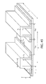
- FIG. 45 is a stringer panel with U-shaped TPM.
- FIG. 46 is a plot showing dimensionless distance between stringers
- FIG. 47 is a plot showing TPM shape width a, b, c versus the panel stress factor
- FIG. 48 is a plot showing TPM shape thickness ⁇ a , ⁇ b , ⁇ c versus the panel stress factor
- FIG. 49 is a plot showing dimensionless panel weight
- G _ s G s l s ⁇ l re 2 ⁇ ⁇ versus the panel stress factor
- FIG. 50 is a plot showing dimensionless distance between stringers
- FIG. 51 is a plot showing dimensionless length of TPM shapes
- a _ a l re
- b _ b l re versus the panel stress factor
- FIG. 52 is a plot showing dimensionless length of TPM shapes
- FIG. 53 is a plot showing dimensionless thickness of U-shaped TPM
- ⁇ _ a ⁇ a l re
- ⁇ _ b ⁇ b l re
- ⁇ _ c ⁇ _ c l re versus panel stress factor
- FIG. 54 is a plot showing dimensionless thickness of TPM
- ⁇ _ b ⁇ b l re
- ⁇ _ c ⁇ c l re versus panel stress factor
- FIG. 55 is a stringer panel with U-shaped TPM possessing inclined lateral web.
- FIG. 56 shows real and optimum-design stringer panels.
- FIG. 57 are tables showing (i) a range of allowable values for stringer panel stress factors, and (ii) features of real and optimum-design panels.
- FIG. 58 shows a rib-reinforced stringer panel.
- FIG. 59 shows scheme for determining of the critical rigidity of ribs.
- FIG. 60 shows scheme for determining of the rigidity of ribs.
- FIG. 61 is a plot of dimensionless weight of the stringer panel
- G _ r G r l ⁇ ⁇ and rib-reinforced stringer panel
- G p.r G p.s + G r versus panel stress ⁇ , material D16-T.
- FIG. 62 is a plot of dimensionless weight of the rib-reinforced stringer panel
- G _ p . s G p . s l ⁇ ⁇ versus distance between ribs l r , material D16-T.
- FIG. 63 is a plot of dimensionless weight of the rib-reinforced stringer panel
- G _ p . r G p . r l ⁇ ⁇ versus skin thickness ⁇ , material D16-T.
- FIG. 64 is a plot of dimensionless weight
- G _ p . r G p . r l ⁇ ⁇ of the rib-reinforced stringer panel versus panel stress ⁇ with varying rib rigidity factor.
- FIG. 65 is a plot of dimensionless weight
- G _ p . r G p . r l ⁇ ⁇ of the rib-reinforced stringer panel versus panel stress ⁇ with varying rib shape factor f r , material D16-T.
- FIG. 66 plots skin thickness ⁇ of the rib-reinforced stringer panel versus linear compressive force q p .
- FIG. 67 plots distance between stringers b s of the rib-reinforced stringer panel versus linear compressive force q p .
- FIG. 68 plots distance between ribs l r of the rib-reinforced stringer panel versus linear compressive force q p .
- FIG. 69 plots characteristic dimensions of stringer shape a, b of the rib-reinforced stringer panel versus linear compressive force q p .
- FIG. 70 plots characteristic thicknesses of stringer shape ⁇ a , ⁇ b of the rib-reinforced stringer panel versus linear compressive force q p .
- FIG. 71 plots optimal stress ⁇ of the rib-reinforced stringer panel versus linear compressive force q p .
- FIG. 72 plots dimensionless weight
- G _ p . r G p . r l ⁇ ⁇ of the rib-reinforced stringer panel versus linear compressive force q p .
- FIG. 73 plots aerodynamic profile of the wing with the specified position of the torsion box.
- FIG. 74 shows a wing design scheme
- FIG. 75 is a table showing coefficients K ⁇ .w , K ⁇ .w in the formulae for web cell critical stresses.
- FIG. 76 is a table showing factor ⁇ versus web cell overall dimensions.
- FIG. 77 is a table showing feasible coefficients for a stringer shape.
- FIG. 78 is a table showing dimensions and geometrical characteristics of rib shape.
- FIG. 79 is a table showing dimensions and geometrical characteristics of pillar shape.
- the present disclosure describes improved TMP and TMP-panel design optimization techniques.
- the techniques utilize advanced mathematical modeling techniques to perform practical multi-parameter associations.
- Structural requirements for load-carrying TPMs and TPM-panel combinations are set to ensure stability and stiffness under compressive load.
- An excessive compression load could, for example, lead to buckling, an unstable condition affecting the TPM but also potentially the surrounding environment.
- Material requirements for load-carrying TPMs and TPM-panel combinations are set to ensure minimum weight objectives at maximum expected load-bearing capacity.
- Fabrication requirements for load-carrying TPMs and TPM-panel combinations are typically associated with manufacture or design specific parameters relating to sizing, cost, proper fit, etc.
- An example set of fabrication type requirements may be requirements that call for minimum thickness of TPM to allow mass production, providing a panel sheet thickness which conforms to standard thickness values, and ensuring that any design allows for any flanges incorporated thereon, for example, to allow the mounting of rivets.
- a constructive restriction is any variable which plays any role whatsoever in the ability to achieve the best possible weight optimization limited only by the available of TPM and/or TPM-panel configurations available for selection by a designer as part of the design process.
- a structural design optimization methodology and tool is herein described.
- the technology pertains to thin wall structures in respect of minimum weight criterion.
- Technology emphasis is the weight optimization of structural metal thin wall load bearing shapes of various configurations and panels. Intended uses include applications spanning the field from aerospace, construction, transportation and other industries.
- the technology aims in part to take advantage of the widespread commercial availability of extruded (rolled) thin wall structures which come in a wide variety of standards and sizes, with H, L, Z, I, C, T, and U-shaped configurations being widely deployed for this reason.
- Aluminum alloy and steel structures are particularly plentiful and common design choices by designers across industries with load bearing design needs.
- the aim of structural design optimization is to be able to achieve reliable thin wall structures which are at the same time light in weight and lower cost if possible.
- the presently proposed solution solves inverse task of structural mechanics for TPMs and TPM-panels: given load, material, pattern of axes, overall size (length, width), and constructive restrictions on the structure, cross-section dimensions are found corresponding to the optimum weight structure.
- design methodologies should allow being able to determine optimum suitable configurations based in large extent on profile of cross-sections and cross-sectional dimensions of structures.
- the system shifts in the direction opposite to the gradient one (the scalar function gradient vector is co-directional with this function's largest increase).
- the gradient method is well suited to solving linear problems.
- the majority of practical parameter optimization problems are nonlinear ones. In this case, the method is time consuming.
- Structural design optimization has been developed in general for such simple structural members as thick wall beams, weighted cross-section bars, trusses, arches, and frames. Thin wall plates, shells, and shapes are significantly less researched. Only those inverse tasks of structural mechanics that have the simplest mathematical models are explored in the thin wall structural design optimization.
- BDM notes “a Z section has no common relationship such as D/t” and enforces “some geometric constraints to dictate its optimum dimensions,” declaring that “In the physical behavior of the Z section, however, this is difficult to achieve.”
- local stability crippling
- cross-sectional dimensions ratios based on the results of the separate local stability problem solved with cross-section area as a variable.
- a scanning methodology is employed (e.g., direct enumeration methodology) and a small number of resulting variables used.
- the proposed process was found to make it possible to scale down the optimization process of a wing box, for example, from 20 to 4 variable geometric parameters. This is described and explained further below.
- the proposed solution does require a high level of familiarity and advanced knowhow of load and material science.
- the present methodology may be utilized during the advanced detailed design stage.
- the ranges can be used early in design to assure a minimum weight structure that will perform with integrity under any load and using any material.
- the ranges enable decreased labor intensity and simplify computation standardization as well as development of standard optimum design programs and design manuals.
- the present invention employs a software-based, model and analysis tool that performs computational analysis on designer-selected TPMs to help in the selection of the appropriate TPM with minimum weight and size for a particular application.
- the proposed approach employs a process whereby the number of simultaneously relevant variables under consideration are decreased using a number of design approaches.
- One such design approach involves a process whereby, starting with an initial structure, a modeling and simulation process is initiated which applies work and stability failure analysis, starting with initial simple calculation methodologies and transitioning to higher level of calculation complexity.
- (i) integrated factors-design indexes, (ii) equal stability principle, and (iii) constructive restriction parameters are all introduced.
- the design output serves as a blueprint for the next stage which is the actual fabrication or manufacturing of the component.
- the final product is based on optimum configurations selected from a fixed set of TMPs with varied cross-sectional shapes; or in the case of TPM-panels, on optimum configurations selected from a fixed set of TMP-panel combinations of varied cross-sectional dimensions.
- the present disclosure uses mathematical modeling to weight-optimize design process without using conventional iterative process analysis and modeling.
- TPM-panel combination arrangements are also known, but as has already been explained, design tools all rely on iterative modeling techniques which suffer the drawbacks already described.
- the present disclosure describes new and novel techniques for selecting optimum design TPMs and TPM-panel combinations that meet constructive restrictions that are optimized for weight.
- the proposed approach is a system of optimization including a problem formulation strategy that is based on applying the inverse task of structural mechanics.
- the system minimizes the number of parameters varied simultaneously, thereby reducing time to design as well as cost of design while a weight optimized solution is achieved.
- the proposed system tool is a promising solution for practical multi-parameter thin wall structure optimization problems completely captured mathematically.
- the system serves to reduce the dimensionality of the problem (decrease the number of simultaneously varied parameters), thereby achieving savings in time and cost of design, by using common design approaches such as:
- a method of scanning (direct enumeration method) a small number of resulting variables is employed. This method of scanning is the single global optimum search method (direct enumeration method). It does not require any special type of functions connecting the sought parameters with the assessment criterion (optimum weight).
- the number of variables in optimization of a wing box are decreased.
- the load carrying components are TPM shapes and TPM-panels.
- TPM-panels are reinforced with stringers or stringers and ribs, and vertical walls manufactured out of sheets reinforced with pillars.
- Each of the above structural members constitutes a certain stage in solution of the general problem of optimization of the wing box.
- the dimensionality of the problem is reduced at each stage.
- variable cross section dimensions of the stringer profile are expressed as a function of the only force compressing the stringer and it does not appear as a variable.
- eight variable parameters taking into account the results of the first stage, are expressed through two variable parameters, the normal stress and the sheet thickness.
- thirteen variable parameters taking into account the results of the second stage, are expressed through the same two variable parameters, the normal stress and the sheet thickness.
- seven variable parameters (independent of the previous parameters) are expressed through two variable parameters, the maximum thickness of the aerodynamic wing profile and the wall thickness.
- variable cross-section dimensions parameters namely the maximum thickness of the aerodynamic wing profile, sheet thickness, wall thickness, and normal stress.
- Each of the considered structural members in wing box design optimization is capable of being independently employed in practice in optimum design of thin wall structures.
- FIGS. 1-8 show a set of distinct TPM configurations associated with a number of different variants defined later below.
- FIGS. 10-15 show various TMP-panel combinations and in some cases from differing perspectives.
- Each TPM is defined by at least a main strip (b) and one or more additional strips which form web- and flange-type strips.
- a web or web strip
- a flange or flange strip
- FIG. 1 shows a TPM (variant TPM I) having a closed rectangular shape, two main web strips and two additional web strips in accordance with an exemplary embodiment of the invention.
- FIG. 2 shows a TPM (also variant TPM I) with closed triangular shape, two main web strips and one further web strip.
- FIG. 3 shows an I-shaped TPM (variant TPM II) which has one main web strip and four flanges.
- FIG. 4 shows a Z-shaped TPM (also variant TPM II) which has one main web strip and two flanges.
- FIG. 5 shows a C-shaped TPM (variant TPM II) with one main web strip and two flanges.
- FIG. 6 shows a T-shaped TPM (variant TPM II) with one main flange and two further flanges.
- FIG. 7 shows an L-shaped TPM (variant TPM II) with one main flange and one further flange.
- FIG. 8 shows a U-shaped TPM (variant TPM Ill) with two main inclined web strips, one web strip and two flanges.
- FIG. 9 diagrammatically maps shape efficiency factor ⁇ as a function of width b, which shall be discussed in greater detail below.
- FIG. 10 is TPM-panel combination formed by joining an L-shaped TPM to a sheet in open cross-section configuration.
- FIG. 11 is an inverted perspective of the configuration in FIG. 10 showing more clearly the I- and L-shaped TPMs positioning on the panel which function to simultaneously reinforce the panel in the longitudinal and transverse directions, respectively.
- FIG. 12 is a sectional view of FIG. 11 taken along line “A-A”.
- FIG. 13 is a further sectional view as seen in the direction of arrow “B” in FIG. 11 .
- FIG. 14 is a cross-sectional perspective of a further TPM-panel configuration defined by a U-shaped TPM in accordance with a further embodiment
- FIG. 15 is a further cross-sectional perspective of a TPM-panel configuration substantially as shown in FIG. 14 but including, in addition to the U-shaped TPM, a further Z-shaped TPM to cooperatively reinforce the panel in both longitudinal and transverse directions, respectively.
- b is the width of the main strip
- ⁇ a is the thickness of the additional strip with common reinforcing ribs
- ⁇ b is the thickness of the main strip.
- the stiffness of the main strip does not exceed the stiffness of the additional strip, specifically, ⁇ a /a ⁇ b /b.
- c is the width of the additional strip with the free reinforcing rib and the common reinforcing rib;
- ⁇ b is the thickness of the main strip
- ⁇ c is the thickness of the additional strip with the free reinforcing rib and the common reinforcing rib.
- the stiffness of the main strip does not exceed the stiffness of the additional strip, specifically, ⁇ c /c ⁇ b /b.
- c is the width of the additional strip with the free reinforcing rib and the common reinforcing rib;
- ⁇ a is the thickness of the additional strip with common reinforcing ribs
- ⁇ b is the thickness of the main strip
- ⁇ c is the thickness of the additional strip with the free reinforcing rib and the common reinforcing rib;
- the stiffness of the main strip does not exceed the stiffness of the additional strip; specifically, ⁇ a /a ⁇ b /b and ⁇ c /c ⁇ b /b.
- the stiffness of the additional strip with common reinforcing ribs does not exceed the stiffness of the additional strip with the free reinforcing rib and the common reinforcing rib; specifically, ⁇ a /a ⁇ b /b and ⁇ c /c ⁇ b /b, which follows from expressions (1), (2), (3) and (4).
- the second type of subject of the group of inventions is two variants of TPM-panel configurations, IV and V (hereinafter, TPM-panel IV and TPM-panel V, or simply panel IV and panel V), based on all said variants of TPM, I, II and III.
- l is the length of the thin wall profile member forming with the sheet the open cross-section configuration
- b c is the pitch of the longitudinal installation of thin wall profile members forming with the sheet the open cross-section configuration.
- the stiffness of the main strip does not exceed the stiffness of the additional strip, and the stiffness of the additional strip with common reinforcing ribs does not exceed the stiffness of the additional strip with the free reinforcing rib and the common reinforcing rib; specifically, ⁇ b /b ⁇ a /a ⁇ c /c.
- the panel IV can be additionally equipped with the TPM installed transversally and having the above relations of the shape dimensions (1)-(4).
- TPM installed transversally and having the above relations of the shape dimensions (1)-(4).
- it is expedient to install these TPM with the pitch of transversal installation l n (10 to 60) b c (7), where: l n is the pitch of transversal installation of thin wall profile member for the case of longitudinally installed thin wall profile member forming with the sheet the open cross-section configuration;
- b c is the pitch of the longitudinal installation of thin wall profile members forming with the sheet the open cross-section configuration.
- l is the length of the thin wall profile members forming with the sheet the closed cross-section configuration
- b 1 c is the pitch of longitudinal installation of thin wall profile members forming with the sheet the closed cross-section configuration.
- the stiffness of the main strip does not exceed the stiffness of the additional strip, and the stiffness of the additional strip with common reinforcing ribs does not exceed the stiffness of the additional strip with the free reinforcing rib and the common reinforcing rib, specifically, ⁇ b /b ⁇ a /a ⁇ c /c.
- the panel according to the variant V can be additionally equipped with the TPM installed transversally and having the above relations of the shape dimensions (1) to (4).
- TPM installed transversally and having the above relations of the shape dimensions (1) to (4).
- it is expedient to install these TPM with the pitch of transversal installation l 1 n (1.5 to 10) b 1 c (9), where:
- l 1 n is the pitch of transversal installation of thin wall profile members for the case of longitudinally installed thin wall profile member farming with the sheet the closed cross-section configuration
- b 1 c is the pitch of the longitudinal installation of thin wall profile members forming with the sheet the closed cross-section configuration.
- the process to be followed involves first providing a TPM having a cross-section that includes at least one of (1) at least two main strips and at least one additional strip having ends connecting with respective ends of two of the at least two main strips and selecting dimensions such that each main strip has a thickness ⁇ b and a width b and the additional strip has a thickness ⁇ a and a width a so that ⁇ b /b is not larger than ⁇ a /a, and (2) at least one main strip and at least one additional strip having one end connecting with an end of the main strip and selecting dimensions such that the main strip has a thickness ⁇ b and a width b and the additional strip has a thickness ⁇ c and a width c and so that ⁇ b /b is not larger than ⁇ c /c.
- the next step involves selecting set of cross-section dimensions ratios values within established ranges values.
- a set of constructive restrictions is established that map to actual cross-section dimensions.
- each of the shape efficiency factor values is defined by:
- a maximum of the shape efficiency factor value ⁇ max is determined from within the respective set of determined shape efficiency factors values ⁇ 1 , ⁇ 2 . . . ⁇ n .
- the proposed approach calculates maximum shape efficiency factor values for different shape TPMs. Once this is done, an overall maximum shape efficiency factor value ⁇ 0max is identified as well as its associated shape. This shape determines among all TPM shapes the best TPM configuration to employ.
- a TPM could be combined with two or more strips. In such cases, if buckling were to occur, it is most likely to occur first in the strips of the TPM.
- This local failure mode may result in overall buckling failure mode and collapse of the entire TPM subject to compression forces. This in turn could lead or contribute to overall TPM-panel combination failure, which could result in severe system or device failure.
- the presently proposed approach therefore is a design optimization technique that algorithmically looks at alternative TPM and TPM-panel combinations, and on the basis of predefined constructive restrictions (structural, material and fabricated requirements) identifies a combination of variables from which cross-section dimensions are determined. By making incremental changes to cross-section dimensions, and for a given pattern, determining possible failure conditions, it is possible to arrive at a best result. This result it has been determined is a much more efficient and cost effective way to select a best pattern than has been done using conventional (usually iterative) techniques.
- TPM-panel combinations IV and V are “wide column” structures, whereas TPMs I-III are all simple or “narrow column” structures, for purposes of discussion. Wide and narrow is used here to describe stability related attributes in overall and local terms.
- a configuration cross-section is “wide”, for instance, when there is both TPM and panel simultaneously being subjected, at that cross-section, to various load-bearing stresses. In case of “narrow” design, only the TPM cross-section is considered to bear load stress.
- “Local” is meant to refer to a “localized failure condition”, i.e., a condition that is limited to the TPM (or TPM-panel combination) only. When the failure condition expands beyond the TPM (or TPM-panel) then there is said to be an “overall failure condition”.
- the sheet (which serves as the panel) provides substantial additional stability to the combination, which is one reason why it is provided.
- the benefit in stability of the sheet is not accounted for.
- the contribution in stability by the sheet is accounted for through appropriate calculations discussed below. This is achieved by treating wide cross-sections the same as narrow cross-sections when performing calculations. The aim is to arrive at a shape efficiency factor that is relevant.
- a TPM is configured to structurally be impacted when a compressive load P is applied.
- the following TPM configurations have been shown: closed rectangle ( FIG. 1 ), closed triangle ( FIG. 2 ), I-shaped ( FIG. 3 ), Z-shaped ( FIG. 4 ), C-shaped ( FIG. 5 ), T-shaped ( FIG. 6 ), L-shaped ( FIG. 7 ), and U-shaped ( FIG. 8 ).
- a TPM may comprise one or more main web strips 2 (as shown in FIGS. 1-5 and 8 ); or one or more main flanges 3 (as shown in FIG. 6 and FIG. 7 ).
- Each TPM may further include one or more main strip(s) 4 characterized by two common longitudinal reinforcing ribs or one free longitudinal reinforcing rib and one common longitudinal reinforcing rib 5 , respectively, as shown in FIGS. 10-15 .
- Additional flange(s) 6 shown in FIGS. 3 to 8
- web strip 7 shown in FIGS. 1, 2 and 8
- FIGS. 1, 2 and 8 may be included and which are defined by (i) a width which is less than that of main strip 4 and (ii) a thickness not less than that of main strip 4 .
- main strip 4 should not exceed that of the additional strip (flanges 6 , web strips 7 ): specifically, ⁇ a /a ⁇ b /b and ⁇ c /c ⁇ b /b.
- the stiffness of the additional strip with two common longitudinal reinforcing ribs, web 7 ( FIG. 8 ) should not exceed the stiffness of the additional strip with one free longitudinal reinforcing rib and one common longitudinal reinforcing rib, flange 6 ( FIG. 8 ): specifically, ⁇ a /a ⁇ c /c.
- the additional flange 6 or the additional web 7 can be located with respect to main strip 4 either at a 90° angle as in FIG. 1, 3 to 7 , or at a different angle as in FIGS. 2 and 8 .
- width a of additional web 7 has its length measured along a cross-section medial line (the line equidistant from longitudinal edge lines of cross-section) of the web 7 between the respective lines of main webs 2 adjacent to the web 7 ( FIGS. 1, 2 and 8 ).
- Width b of main web 2 or flange 3 has its length measured along the medial line of the cross-section of main web 2 or flange 3 between the respective lines of adjacent strips ( FIGS. 1 to 8 ).
- Width c of additional flange 6 has its length measured along the medial line of the cross-section of flange 6 from the medial line of main web 2 or flange 3 to the free longitudinal reinforcing rib of additional flange 6 ( FIGS. 3 to 8 ).
- Thickness ⁇ a , ⁇ b , and ⁇ c corresponding to dimensions a, b, c is defined as the distance measured between the edges of cross-sections of webs and flanges.
- TPM I, II or III are employed with following shapes: I-shape with one main web 2 and four additional flanges 6 ( FIG. 3 ); Z-shape ( FIG. 4 ) with two additional flanges 6 located both sides from the main web 2 ; or C-shape with additional flanges 6 located the same side of the main web 2 ( FIG. 5 ); or U-shape with main webs 2 , additional web 7 and additional flanges 6 ( FIG. 8 ); or T ( FIG. 6 ) and L ( FIG. 7 )—with the main flange 3 and additional flange(s) 6 ; or closed rectangular ( FIG. 1 ) and triangular ( FIG. 2 ); as well as shapes with other arrangement and quantity of main and additional webs and flanges.
- K f (i 2 /F) 2/5 is an overall stability factor
- K m K 1/5 /(b/ ⁇ b ) 2/5 is a local stability factor
- ⁇ b are the width and the thickness of the main web 2 or flange 3 , respectively;
- i, F are the radius of gyration and the area of shape of any TPM shown in FIGS. 1 to 8 , respectively;
- K is the coefficient in the known formula for local stability critical stress, depending on ratios (1), (3), (10) of TPM shape dimensions.
- TPMs may be compared in terms of weight as well. The greater the maximum value of factor ⁇ for a particular shape, the less its TPM weight.
- the graphic illustration of the shape efficiency factor ⁇ versus the width b of the main strip is shown in FIG. 9 .
- the factor ⁇ possesses, for each shape, a maximum value.
- a corresponding shape efficiency factor maximum value exits that falls inside a range of ratio values.
- FIG. 9 therefore illustrates the significance of a shape efficiency factor.
- the local stability factor K m that characterizes local stability decreases.
- the function of the shape efficiency factor has its maximum value (this being different for different TPM cross-section shapes). Furthermore, this maximum value ensures the minimum TPM shape cross-section area (and hence the minimum weight).
- the idea is to use a programming tool that algorithmically reduces the design choice down to a best TPM selection based on predefined, or otherwise known, cross-section dimension ratio values falling with a desired range.
- the tool will recognize when certain cross-section dimension ratios appear to have fallen outside a desired range of values and prompt the designer to select a different TPM, or change the material of the TPM. In the latter instance, a stronger material will necessarily change the shape efficiency factor for a TPM of a given shape.
- FIG. 10 shows a TPM-panel combination of variant IV.
- This variant is based on the L-shaped variant TPM II described above and shown in FIG. 7 .
- a TPM-panel In a fully-deployed state, a TPM-panel will be subjected primarily to a compressive load q directed along a length l that's distributed across a width B of the TPM-panel.
- the TPM-panel includes sheet 8 and a variant type TPM II attached to one of the sides 9 of this sheet 8 across its width and installed longitudinally with even pitch. Multiple TPMs (variant II) are shown.
- Each TPM is integrably coupled to sheet 8 in an open cross-section configuration.
- Each TPM II is an L-shape type TPM and consists of main flange 3 and one additional flange 6 .
- b c is the pitch of the longitudinal installation of the TMPs resting on sheet 8 in the open cross-section configuration shown and described;
- l is the length of TPM II.
- the stiffness of the main strip does not exceed the stiffness of the additional strip, specifically, ⁇ c /c ⁇ b /b.
- FIG. 14 shows a TPM-panel (variant V) which is based on a TPM of variant III of U-shape (as in FIG. 8 ).
- the TMP is formed with sheet 8 in closed cross-section configuration.
- Each TPM III is characterized by main webs 2 , additional web 7 and additional flanges 6 .
- ⁇ is the thickness of the sheet 8 ;
- b 1 c is the pitch of the longitudinal installation of thin wall profile members forming with the sheet 8 the closed cross-section configuration
- l is the length of TPM III.
- the stiffness of the main strip should not exceed the stiffness of the additional strip, and the stiffness of the additional strip with common reinforcing ribs should not exceed the stiffness of the additional strip with the free reinforcing rib and the common reinforcing rib, specifically, ⁇ b /b ⁇ a /a ⁇ c /c.
- TPM-panels IV and V in longitudinal direction, additional TPMs of variant I, II and III are shown embodied.
- TMP shapes including for example, Z-, T-, C-, rectangular, or triangular shapes.
- TPM-panels IV and V shown in FIGS. 10 and 14 function as follows.
- the distributed compressive load q is reacted by both TPM I, II, III and the sheet of TPM-panel 8 .
- the load-bearing capacity of the TPM-panels IV, V is provided for by virtue of selection of optimum dimensions of cross-section of the panel: dimensions of shapes of TPM are selected basing on the expressions of equations (1), (3), (4) and (10); the thickness of sheet 8 and the pitch of TPM longitudinal installation that have been selected based on rules satisfying the expressions in equations (5), (6) and (8), respectively.
- FIGS. 11-13 and 15 show panels IV, V with TPM II, Ill installed both longitudinally and transversally.
- FIGS. 11 to 13 show panel IV based on longitudinally installed I-shaped TPM II and transversally installed L-shaped TPM II.
- TPM-panel IV In its course of operation, a TPM-panel IV will reacts primarily to any compressive load q directed along length L of any longitudinally installed TPM (see pos. 11 in FIGS. 11 and 12 ). These same TPMs are attached to one of the sides 12 of sheet 10 across its width and formed integrally with sheet 10 in open cross-section configuration.
- TPM 13 are installed transversally with even pitch across the length of the same side 12 of sheet 10 and are embodied with cut-outs 14 in which the longitudinally installed TPM 11 are located ( FIGS. 11-13 ).
- TPM 11 possesses the main web 15 embodied as the main strip 16 ; at each of its reinforcing ribs 17 , an additional flange 18 is formed with the width less than that of the strip 16 and with thickness not less than that of the strip 16 ( FIG. 12 ).
- Each transversally installed TPM 13 is embodied as an L-shape and possesses a main flange 19 embodied as a main strip 20 across the width of which, at one of its longitudinal reinforcing ribs 21 , an additional flange 22 is formed ( FIG. 13 ).
- L is the length of the panel
- n n is the number of transversally installed TPM 13 ;
- ⁇ is the thickness of the sheet 10 ;
- b c is the pitch of the longitudinal installation of TPM 11 forming with the sheet 10 the open cross-section configuration.
- FIG. 15 shows the TPM-panel V based on the longitudinally and transversally installed members 11 and 13 , respectively.
- the longitudinally installed TPM 11 is embodied as a U-shape and formed with sheet 10 in closed cross-section configuration.
- the transversally installed member 13 is of a Z-shape.
- the stiffness of the main strip should not exceed the stiffness of the additional strip, and the stiffness of the additional strip with common reinforcing ribs should not exceed the stiffness of the additional strip with the free reinforcing rib and the common reinforcing, specifically, ⁇ b /b ⁇ a /a ⁇ c /c.
- b 1 c is the pitch of installation of U-shaped TPM 11 formed with sheet 10 in closed cross-section configuration
- L is the length of the panel
- n 1 n is the number of transversally installed TPMs 13 .
- n n and n 1 n are the number of transversally installed TPMs for those longitudinal TPMs formed with the sheet in open and closed cross-section configurations, respectively.
- TPM-panels IV and V For transversal and longitudinal reinforcing of TPM-panels IV and V, TPM of other shapes can also be employed.
- the load-bearing capacity of the panel is provided for by virtue of selection of the optimum dimensions of cross-sections of longitudinally and transversally installed TPM, thickness of the sheet, pitches of longitudinal and transversal installation corresponding to the minimum weight of the panel.
- TPM-panels are not as commonly used as simple TPM configurations, the mathematical relations expressed by (1), (3) and (10) are equally relevant to TPM-panels as they are to TMP-only configurations.
- the process to be followed involves first providing a TPM having a cross-section that includes at least one of (1) at least two main strips and at least one additional strip having ends connecting with respective ends of two of the at least two main strips and selecting dimensions such that each main strip has a thickness ⁇ b and a width b and the additional strip has a thickness ⁇ a and a width a so that ⁇ b /b is not larger than ⁇ a /a, and (2) at least one main strip and at least one additional strip having one end connecting with an end of the main strip and selecting dimensions such that the main strip has a thickness ⁇ b and a width b and the additional strip has a thickness ⁇ c and a width c and so that ⁇ b /b is not larger than ⁇ c /c.
- the next step involves selecting set of cross-section dimensions ratios values within established ranges values.
- a set of constructive restrictions is established that map to actual cross-section dimensions.
- each of the shape efficiency factor values is defined by:
- K f (i 2 /F) 2/5 is an overall stability factor
- K m K 1/5 /(b/ ⁇ b ) 2/5 is a local stability factor
- ⁇ b are the width and the thickness of the main strip, respectively.
- i, F are the radius of gyration and the cross-section area, respectively.
- K is the coefficient in the known formula for local stability stress.
- a maximum of the shape efficiency factor value ⁇ max is determined from within the respective set of determined shape efficiency factors values ⁇ 1 , ⁇ 2 . . . ⁇ n.
- the proposed approach calculates maximum shape efficiency factor values for different shape TPMs. Once this is done, an overall maximum shape efficiency factor value ⁇ 0max is identified as well as its associated shape. This shape determines among all TPM shapes the best TPM configuration to employ.
- FIG. 16 is a high-level flow diagram 100 describing the operation flow of a model and analysis TPM design tool configured for selecting an optimum weight TPM in accordance with an exemplary embodiment.
- the proposed process of designing TPMs is facilitated by a model and analysis design tool.
- the tool performs computational analysis on relevant input variables.
- the input stage involves the designer inputting into the tool relevant design parameters (step 120 ).
- the relevant design parameters may include preset parameters such as concentrated compressive force value, material properties (compression yield stress value, compression proportionality limit value, tensile ultimate stress value, compression limiting stress value, compression normal modulus value), pattern of axes, length of the TPM under analysis, and other relevant parameters.
- the tool uses the received parameters to establish weight minimization parameters which include consideration of constructive restrictions (including fabricated restrictions) to TPM cross-section dimensions (step 130 ). Finally, the designer is asked to select from set of TPM cross-section dimension ratio values, respecting fabrication requirements of previous step, within pre-established TPM range values (step 140 ).
- the tool Having received all relevant input date, the tool must process the set of ratio values, respecting constructive restrictions, to obtain corresponding set of shape efficiency factor values (step 150 ).
- the processing in the previous step results in identification of optimum ratio values according to maximum shape efficiency factor value (step 160 ).
- the tool then calculates a maximum stress value using the maximum shape efficiency factor value to obtain maximum stress value (step 170 ).
- the tool calculates optimum cross-section dimension values using maximum stress value and optimum ratio values.
- FIG. 17 is a high-level flow diagram 200 describing the operation flow of a model and analysis TPM design tool configured for selecting an optimum weight TPM-panel in accordance with a further exemplary embodiment.
- a first step in design optimization of TPM-panel combinations involves receiving preset panel uniform compressive force value; panel material properties (TPM and sheet)—compression yield stress value, compression proportionality limit value, tensile ultimate stress value, compression limiting stress value, compression normal modulus value; pattern of axes (TPM shape); and panel length and width (step 210 ). Any constructive (including fabricated) restrictions to TPM-panel including minimum feasible sheet thickness value are established and entered into the tool to be used in its calculations (step 220 ). Steps 210 and 220 are part of the input stage functions performed by the tool.
- the tool is ready to begin processing this information. This is performed by a calculations stage.
- the first calculation is to generate a maximum panel stress value (step 230 ), followed by generating TPM concentrated compressive force value (step 240 ). This then is followed by generating minimum weight cross-section dimensions values using the methodology described in operational flow diagram 100 (step 250 ). The tool then calculates and generates an optimum pitch value of longitudinally installed TPMs (step 260 ). In the final step 270 , the optimum pitch value of transversal installation TPMS is obtained.
- the solution of the panel optimization problem is based on the existing methods of direct calculations of its strength, as well as on the results obtained in solution of the problem of the optimum compressed TPM.
- the panel is considered as a “wide column” losing stability simultaneously in overall and local modes. It is assumed in the practice of TPM-reinforced panels that the link of TPM with skin is pivotal. In this assumption, in the local stability calculations, the mutual effect of TPM and skin is not accounted for, while in the overall stability calculations the effect of the skin is accounted for through the effective bending rigidity of the TPM. In the calculation scheme selected, the shape efficiency factor for a “wide column” shall be assumed the same as for the “simple (narrow) column”.
- the panel with Z-shape TPM (forming with the sheet an open configuration) shall be considered.
- the panel with the U-shaped TPM (forming with the sheet a closed configuration)
- the final results are presented.
- the results of calculations are presented for panels with U-shaped, Z-shaped and L-shaped TPM.
- the constructive restrictions associated with the panel sheet include a minimum feasible sheet thickness value, as well as at least one of a preset panel uniform compressive force value, panel material properties, TPM pattern of axes, and a length and width of panel.
- the calculating of at least one of the first and second sets of optimum cross-section dimensional values of a corresponding TPM involves identifying a set of TPM cross-section dimensional ratio values, and calculating from a set of inter-dependent parameters, including the set of TPM cross-section dimensional ratio values, the optimum cross-section dimensional ratio values of the TPM.
- the set of inter-dependent parameters includes the corresponding one of the set of first and second constructive restrictions.
- Each of the first and second sets of constructive restrictions is determined from at least one of a preset concentrated compressive force value, material properties, pattern of axes, and a length of the associated TPM.
- a Z shape is shown in FIG. 4 while an I shape is shown in FIG. 5 .
- TPMs with four variable shape dimensions b, ⁇ b , c, and ⁇ c .
- a Z-shaped TPM may very well be a best option.
- Table 2 has similar calculations as those in Table 1 but this time for an I-shaped TPM.
- shape efficiency factor values of ⁇ 1 , ⁇ 2 based on the ratios values in Variants 1 , 2 , respectively, and which are within the ranges for the Z shape and the I shape TPMs, that the shape efficiency factor values are not significantly less than the theoretical maximum value ⁇ max for a given shape.
- a TPM is implicitly associated with a shape efficiency factor with theoretical maximum values. For various TPM shapes, these theoretical maximum values fall inside specified ranges. Inside the ranges, for each TPM shape, the values of the shape efficiency factor have insignificant deviation from its theoretical maximum values and thus insignificant deviation from its theoretical minimum weight values. Outside the ranges, the shape efficiency factor values decrease significantly, as a consequence of which so does the overall weight in design. In all other regards, techniques for setting the ratios themselves to feasible and workable dimensions and which comply with a given set of constructive restrictions is known and beyond the scope of this invention.
- various shapes of TPM can be compared in weight: the greater the maximum value of the shape efficiency factor ⁇ for a particular shape, the less is the TPM weight.
- a plurality of maximum shape efficiency factors values ⁇ max 1, ⁇ max 2 . . . ⁇ max N are determined, an overall maximum shape efficiency factor value ⁇ 0max is determined and the TPM of the shape having the overall maximum shape efficiency factor value ⁇ 0max is produced by known methods.
- the proposed method of producing minimum weight transversal and longitudinal reinforcing panels IV and V with respect to constructive restrictions comprising the steps similar to method of producing a minimum weight TPM and including expressions (1) (9).
- an analysis scheme for a representative thin wall profile member has been selected that is very close to the existing efficient calculation method.
- a method is the theory of stability of compressed strips forming the TPM (with regard to their operation within supercritical range in respect of stability).
- the selected analysis scheme predetermines the character and sequence of destruction of a compressed TPM.
- a TPM is considered as a solid-walled structural member consisting of plate (strips). Therefore it is possible that prior to the loss of the stability of the TPM as a whole (overall stability loss), the strips forming the TPM would have suffered (local) buckling (which is characterized by warp of the cross-section, linearity and position of common longitudinal ribs of the strips being maintained). This may result in destruction of the entire compressed TPM.
- Geometrical irregularities (initial eccentricity of load application and bends) reduce critical stresses and, consequently, reduce the load-carrying capacity of the TPM. Calculations errors (of loads, stresses, deformations) and adopted assumptions of the selected analysis scheme are refined later in compliance with the Design Standards.
- the proposed model uses the following design approaches: 1) proceeding from simple design schemes to more complicated ones basing on analysis of various forms of stability loss of the structure; 2) introduction of generalizing coefficients (shape efficiency factor et al.); 3) employment of equal stability principle; 4) introduction of constructive restrictions.
- the suggested model using these design approaches enable analytical representation of the dimensions of cross-section (shape dimensions) of compressed TPM having the minimum weight.
- the compressed TPM is considered as a “simple column” possessing high torsional rigidity.
- their high torsional rigidity is provided for.
- ⁇ ⁇ _ ef ⁇ x _ k 0
- ⁇ ef t ef / q
- t ef t ef /l re
- q q/l re
- t ef being the effective thickness (area divided by unit length of cross-section).
- Stresses ⁇ cr. l (x i ) and ⁇ cr. tot (x i ) shall be monotony decreasing with x k .
- thickness function ⁇ ef (x i ) and critical stress functions ⁇ cr. l (x i ), ⁇ cr. tot (x i ) should be expressed in terms of TPM shape dimensions x i .
- TPM dimensionless parameters a 1 , a 2 . . . a n as ratios of TPM shape dimensions to characteristic dimensions.
- Characteristic dimensions a, ⁇ a shall be defined as the dimensions of the main strip appearing in the formula of local stability critical stress.
- FIG. 18 is a plot showing factor Ks versus ratios of U-shaped TPM dimensions.
- FIG. 19 is another plot showing factor Ks versus ratios of U-shaped TPM dimensions.
- FIG. 20 is yet another plot showing factor Ks versus ratios of U-shaped TPM dimensions.
- FIG. 21 is a plot showing factor Ks versus ratios of Z-shaped TPM dimensions.
- FIG. 22 is a plot showing factor Ks versus ratios of L-shaped TPM dimensions.
- FIG. 23 is a plot showing factor Ks versus ratios of I-shaped TPM.
- ⁇ _ ef ⁇ _ a ⁇ f 1 ⁇ ( a 1 , a 2 , ... ⁇ , a n ) q _ c , ( 1.1 ⁇ .5 ) the local stability critical stress
- ⁇ s is TPM flexibility
- ⁇ s l re /i
- ⁇ ⁇ 0 - ⁇ 0 - ⁇ pr ⁇ s * ⁇ ⁇ s , ( 1.2 ⁇ .1 )
- ⁇ s * is the limiting flexibility of TPM
- ⁇ s * ⁇ ⁇ E ⁇ pr .
- TPM stress can be expressed in terms of flexibility by equation (1.1.7).
- ⁇ s From equations (1.1.7) and (1.2.1), we obtain the ductility factor as follows:
- ⁇ ⁇ ⁇ ⁇ pr ⁇ ( ⁇ 0 - ⁇ ⁇ 0 - ⁇ pr ) 2 . ( 1.2 ⁇ .2 )
- P _ s P s l re 2 is the TPM stress factor.
- a _ ( P _ s ⁇ ⁇ ⁇ s ) 1 / 3 ⁇ A 1 ⁇ ⁇ 1 / 12 , ( 1.3 ⁇ .3 ) ⁇ _ a ⁇ ( P _ s 2 ⁇ ⁇ ⁇ s 2 ) 1 / 3 ⁇ ⁇ ⁇ 1 / 12 ⁇ A 2 , ( 1.3 ⁇ .4 ) , A 1 , A 2 are functions of dimensionless parameters.
- a 1 ( K s ⁇ a _ 4 ⁇ ⁇ _ a 2 F _ s ⁇ J _ s ) 1 / 6 , ( 1.3 ⁇ .5 )
- a 2 ( a _ 2 ⁇ ⁇ _ a 4 ⁇ J _ s K s ⁇ F _ s 5 ) 1 / 6 . ( 1.3 ⁇ .6 )
- TPM The dimensionless weight of TPM can be expressed as:
- TPM shape dimensions are essentially functions of characteristic dimensions a op , ⁇ a op and dimensionless parameters a 1 op , a 2 op . . . , a n op .
- FIG. 41 is a table showing feasible dimensions of U-shaped TPM.
- FIG. 24 is a plot showing shape efficiency factor A versus ratios of U-shaped TPM dimensions.
- FIG. 25 is plot showing shape efficiency factor A versus ratios of U-shaped TPM dimensions.
- FIG. 26 is yet plot showing shape efficiency factor A versus ratios of U-shaped TPM dimensions.
- FIG. 27 is a plot showing scaled (dimensionless) characteristic dimension
- a _ a l re versus TPM stress factor
- FIG. 28 is a plot showing scaled (dimensionless) characteristic dimension
- P s _ P s l re 2 , U-shaped TPM.
- FIG. 29 is a plot showing optimum stress ⁇ s versus TPM stress factor
- P s _ P s l re 2 , U-shaped TPM.
- FIG. 30 is a plot showing dimensionless weight
- G s _ G s l s ⁇ l re 2 ⁇ ⁇ versus TPM stress factor
- P s _ P s l re 2 , U-shaped TPM.
- TPM shape dimensions could be varied.
- ⁇ b can prove too low value (less than 1 mm), which makes it difficult to manufacture such a profile in mass-scale production.
- the most suitable for production is a constant thickness profile with
- profile No. 2 is selected as the most feasible one.
- the thickness of the U-shaped TPM webs can to be very low value and technologically not feasible. If this is the case, Z-shaped and L-shaped profiles with the configuration open with the skin sheet should be selected.
- FIG. 31 is a plot showing shape efficiency factor A versus ratios of Z-shaped TPM dimensions.
- FIG. 32 is a plot showing scaled (dimensionless) characteristic dimension
- P _ s P s l re 2 , Z-shaped TPM.
- FIG. 33 is a plot showing scaled (dimensionless) characteristic dimension
- ⁇ _ b ⁇ b l re versus TPM stress factor
- P _ s P s l re 2 , Z-shaped TPM.
- FIG. 34 is a plot showing optimum stress ⁇ s versus TPM stress factor
- P _ s P s l re 2 , Z-shaped TPM.
- FIG. 35 is a plot showing dimensionless weight
- G _ s G s l s ⁇ l re 2 ⁇ ⁇ versus TPM stress factor
- P _ s P s l re 2 , Z-shaped TPM.
- FIG. 36 is a plot showing shape efficiency factor A versus ratio of L-shaped TPM dimensions.
- FIG. 37 is a plot showing scaled (dimensionless) characteristic dimension
- FIG. 38 is a plot showing scaled (dimensionless) characteristic dimension
- ⁇ _ b ⁇ b l re versus TPM stress factor
- FIG. 39 is a plot showing optimum stress ⁇ s versus TPM stress factor
- FIG. 40 is a plot showing dimensionless weight
- G _ s G s l s ⁇ l re 2 ⁇ ⁇ versus TPM stress factor
- Panel design comes down to finding of six dimension of its cross-section b, ⁇ b , c, ⁇ c , b s , ⁇ given the linear compressive force q p , overall dimensions B, l and panel material.
- FIG. 42 shows a panel with Z-shaped TPM.
- TPM shape dimensions b, ⁇ b , ⁇ c are determined according to equations (1.3.3), (1.3.4), given the force P s per one stringer.
- the unknown variables in this case would be pitch of TPM installation b s , skin thickness ⁇ and force P s per one stringer.
- the panel weight G s.p is determined by the sum of weight of TPM (stringers) G s , and the weight of the skin G sk according to the equation:
- G _ s . p . P _ s ⁇ s ⁇ b _ s + ⁇ _ ⁇ ⁇ ⁇
- Equation (1.3.7) enables to consider as a sought-for parameter the stringer stress ⁇ s rather than the stress factor P s .
- Equation (2.1.8) cannot be solved with respect to ⁇ s .
- G _ s . p . q _ p ⁇ ⁇ s ( ⁇ ⁇ E ) 2 ⁇ ⁇ _ 2 ⁇ K p 1 2 ⁇ ( ⁇ ⁇ ⁇ A ) 5 / 2 + ⁇ s 2 + ⁇ _ . ( 2.1 ⁇ .11 )
- FIG. 43 is a graph showing dimensionless panel weight
- G _ s G s l s ⁇ l re 2 ⁇ ⁇ ⁇ versus TPM stress ⁇ s , U-shaped TPM.
- the value of the shape efficiency factor varies insignificantly with changing of the TPM shape and does not affect considerably the results of calculations according to (2.1.11).
- the lower limit value for the pitch of longitudinal installation of TPM is determined by the value of the critical skin stress ⁇ cr.sk (2.1.6).
- the critical stress in the skin cannot exceed the critical stress in the TPM. Therefore, the optimum panel weight is achieved provided equality of critical stresses of skin and TPM, that is, ruling out skin buckling.
- the lower limit value for reducing TPM shape dimensions is determined by the minimum TPM shape moment of inertia, providing for the wavelength (in stability loss) in the panel width equal to or less than the distance between the rivet joint of TPM fastening to the skin. Reduction of TPM shape dimensions is evidently restricted also by the constructive restrictions to TPM.
- Expression (2.2.4) implies that for a panel with the non-buckling skin, the minimum weight is reached at the maximum panel stress.
- TPM stress factor (2.1.10) taking into account (2.2.5) and (2.2.1):
- the optimum characteristic dimensions of the shape taking into account (2.2.6), shall be determined from equations (1.3.3) and (1.3.4).
- the characteristic dimensions of the TPM shape are constant values, while absolute dimensions depend linearly from the panel length (1.1.1)-(1.1.3).
- the second sought-for parameter, the dimensionless pitch of longitudinal installation b s can be determined from the equation (2.2.2), should the third sought-for parameter be found, namely, the dimensionless skin thickness ⁇ .
- Expressions (2.2.1) and (2.2.5) enable finding the dimensionless skin thickness.
- ⁇ _ 1 , 2 ⁇ 2 ⁇ ⁇ ⁇ ( ⁇ 4 ⁇ ⁇ 2 - ⁇ ⁇ ) 1 / 2 . ( 2.2 ⁇ .9 )
- ⁇ _ 1 , 2 q _ p 2 ⁇ ⁇ 0 , 2 ⁇ q _ p 2 4 ⁇ ⁇ 0 , 2 2 - ( ⁇ 0 , 2 E ⁇ ⁇ ) 2 ⁇ 1 ( A ⁇ ⁇ ⁇ ) 5 / 2 ⁇ K p 1 / 2 . ( 2.2 ⁇ .10 )
- FIG. 45 is a stringer panel with U-shaped TPM.
- TPM For the U-shaped (forming with the sheet a closed configuration) TPM, the dimensionless pitch of longitudinal installation of TPM is determined from the following equation:
- ⁇ 1 , 2 q _ p 2 ⁇ ⁇ 0 , 2 - a _ + c _ 2 ⁇ ( ⁇ 0 , 2 K p ⁇ E ) 1 / 2 ⁇ ⁇ [ q _ p 2 ⁇ ⁇ 0 , 2 - a _ + c _ 2 ⁇ ( ⁇ 0 , 2 K p ⁇ E ) 1 / 2 ] 2 - 1 E 2 ⁇ ⁇ 2 ⁇ ( ⁇ ⁇ ⁇ A ) 5 / 2 ⁇ K p 1 / 2 + q _ p ⁇ ( a _ + c _ ) ( K p ⁇ E ⁇ ⁇ 0 , 2 ) 1 / 2 . ( 2.2 ⁇ .13 )
- FIG. 57 are tables showing (i) a range of allowable values for stringer panel stress factors, and (ii) features of real and optimum-design panels.
- a stringer panel shall be designed for any feasible linear compressive loads q p , or if dimensions of the panel cross-section do not meet the constructive restrictions, then the optimum stress shall be considered the stress ⁇ n , which would be less than the yield stress, that is, ⁇ n ⁇ 0.2 .
- the panel would possess the least feasible weight rather than theoretical minimum weight (i.e. the minimum weight accounting for said restrictions).
- ⁇ ⁇ ⁇ n ⁇ pr ⁇ ( ⁇ 0 - ⁇ n ⁇ 0 - ⁇ pr ) 2 . ( 2.3 ⁇ .5 )
- the minimum dimensionless skin thickness is determined from the expression
- ⁇ _ m ⁇ ⁇ i ⁇ ⁇ n ⁇ m ⁇ ⁇ i ⁇ ⁇ n l re .
- ⁇ min (0.8-1) mm.
- the countersunk-headed rivets are not employed, as they do not ensure adequate skin fastening strength. Cup-headed rivets are not employed due to aerodynamic restrictions.
- FIG. 44 is a graph showing dimensionless skin thickness
- ⁇ _ ⁇ l re versus the panel stress factor
- FIG. 46 is a graph showing dimensionless distance between stringers
- FIG. 47 is a plot showing TPM shape width a, b, c versus the panel stress factor
- FIG. 48 is a plot showing TPM shape thickness ⁇ a , ⁇ b , ⁇ c , versus the panel stress factor
- FIG. 49 is a plot showing dimensionless panel weight
- G _ s G s l s ⁇ l re 2 ⁇ ⁇ versus the panel stress factor
- FIG. 50 is a plot showing dimensionless distance between stringers
- FIG. 51 is a plot showing dimensionless length of TPM shapes
- FIG. 52 is a plot showing dimensionless length of TPM shapes
- FIG. 53 is a plot showing dimensionless thickness of U-shaped TPM
- ⁇ _ a ⁇ a l re
- ⁇ ⁇ _ b ⁇ b l re
- ⁇ ⁇ _ c ⁇ _ c l re versus panel stress factor
- FIG. 54 is a plot showing dimensionless thickness of TPM
- ⁇ _ b ⁇ b l re
- ⁇ ⁇ _ c ⁇ c l re versus panel stress factor
- FIG. 55 is a stringer panel with U-shaped TPM possessing inclined lateral web.
- the optimum inclination angle of the lateral web is:
- the optimum pitch t riv shall be selected for TPM fastening to the skin.
- the pitch t riv is determined basing on equality of the overall stability critical stress for the skin between the rivets ⁇ cr.riv and the stringer critical stress ⁇ s , that is
- the benchmark data were obtained for panels of torsion box wings of the airliner TU-154.
- two panels considerably differing in compressive loads are regarded.
- the panels were designed for the compressive load q p constituting, respectively, 934 daN/cm and 555 daN/cm.
- the longitudinal set (stringers) of these panels is manufactured out of the standard Z-shaped profiles: Pr 105-9 and Pr 105-1.
- the profiles were fastened to the skin with rivets.
- FIG. 56 shows real and optimum design stringer panels.
- Design of optimum weight panels using method in 2.3 decreased panel weights by 19.1% and 19.2%, respectively.
- FIG. 58 shows a rib-reinforced stringer panel.
- FIG. 59 shows scheme for determining of the critical rigidity of ribs.
- FIG. 60 shows scheme for determining of the rigidity of ribs.
- FIG. 61 is a plot of dimensionless weight of the stringer panel
- G _ r G r l ⁇ ⁇ and rib-reinforced stringer panel
- G p.r G p.s + G r versus panel stress ⁇ , material D16-T.
- FIG. 62 is a plot of dimensionless weight of the rib-reinforced stringer panel
- G _ p . s G p . s l ⁇ ⁇ versus distance between ribs l r , material D16-T.
- FIG. 63 is a plot of dimensionless weight of the rib-reinforced stringer panel
- G _ p . r G p . r l ⁇ ⁇ versus, skin thickness ⁇ , material D16-T.
- FIG. 64 is a plot of dimensionless weight
- G _ p . r G p . r l ⁇ ⁇ of the rib-reinforced stringer panel versus panel stress ⁇ with varying rib rigidity factor.
- FIG. 65 is a plot of dimensionless weight
- G _ p . r G p . r l ⁇ ⁇ of the rib-reinforced stringer panel versus panel stress ⁇ with varying rib shape factor f r , material D16-T.
- FIG. 66 is a plot of skin thickness ⁇ of the rib-reinforced stringer panel versus linear compressive force q p .
- FIG. 67 is a plot of distance between stringers b s , of the rib-reinforced stringer panel versus linear compressive force q p .
- FIG. 68 is a plot of distance between ribs l r of the rib-reinforced stringer panel versus linear compressive force q p .
- FIG. 69 is a plot of characteristic dimensions of stringer shape a, b of the rib-reinforced stringer panel versus linear compressive force q p .
- FIG. 70 is a plot of characteristic thicknesses of stringer shape ⁇ a , ⁇ b of the rib-reinforced stringer panel versus linear compressive force q p .
- FIG. 71 is a plot of optimal stress ⁇ of the rib-reinforced stringer panel versus linear compressive force q p .
- FIG. 72 is a plot of dimensionless weight
- G _ p . r G p . r l ⁇ ⁇ of the rib-reinforced stringer panel versus linear compressive force q p .
- the discussed method is subdivided into the following stages: formulation of the problem, selection of the force pattern, determining of the required moment of inertia for a rib and derivation of the analytical expression for the rib-reinforced stringer panel.
- TPM stringer or rib
- the number of their variable dimensions can be different. Solution of this problem, as it will be shown below, does not depend on the number of dimensions of the stringer or rib shape.
- cross-section dimensions of the panel are determined, that is, stringer shape dimensions, rib shape dimensions, pitch of stringer installation b s , pitch of ribs installation l r , skin thickness ⁇ basing on the overall panel minimum weight condition ( FIG. 58 ).
- the benchmark parameters are considered panel overall dimensions B and l, linear compressive load q p and the panel material.
- designing of a rib-reinforced stringer panel is reduced to determining of the panel stress ⁇ , skin thickness ⁇ , rib moment of inertia J r and the pitch of rib installation l r . It will be shown later that the parameters J r and l r could be expressed through parameters ⁇ and ⁇ . So, in the final analysis, designing of the rib-reinforced stringer panel is reduced to finding the two variable parameters, panel stress ⁇ and skin thickness ⁇ .
- the rib-reinforced stringer panel is a complex spatial structure.
- the following calculation scheme is adopted for optimization of the parameters of the former: the stringers are considered to be isolated rods on elastic supports.
- the elastic supports are considered to be the ribs ( FIG. 59 ).
- the ribs are regarded as double-support hinged beams leaning on longerons.
- the skin participates in the panel operation across the reduced width along with stringers and ribs.
- the worst operating conditions will be experienced by the stringer located across the panel width in the middle of the latter, as it would have the least rigidity of elastic supports (for this stringer, the ribs have the maximum deflection). Assuming that destruction of a single stringer entails destruction of the panel as a whole, we assume the basic stringer to be the one located across the panel width in its middle.
- the critical rigidity of supports is determined through the following expression:
- r r c ⁇ ⁇ 2 ⁇ E ⁇ J s ⁇ ⁇ l r 3 ⁇ ⁇ ⁇ . ( 3.1 ⁇ .3 )
- the sought-for required rib moment of inertia J r.rq is determined from the condition of equality of rib critical rigidity and rigidity of the rib considered as double-support beam.
- r r K ex ⁇ 48 ⁇ E ⁇ J r . rq B 3 , ( 3.1 ⁇ .4 )
- K ex is the experimental factor accounting for the actual rigidity of the rib within the wing; K ex ⁇ 1.
- J r , rq c ⁇ ⁇ 2 ⁇ B 3 ⁇ J s 48 ⁇ K ex ⁇ ⁇ ⁇ l r 3 ⁇ ⁇ ⁇ . ( 3.1 ⁇ .5 )
- the force per one stringer P s is determined through (2.2.3); the pitch of stringer installation b s in (2.2.3) is determined through equations (2.2.2) or (2.5.2).
- the panel weight is equal to the total of the weight of the longitudinal (stringers with skin) and transversal (ribs) sets.
- the rib area is determined according to the formula
- F r ( J r f r ) 1 2 , ( 3.1 ⁇ .8 ) f r is the rib shape factor.
- the shape factor is determined after the rib strength calculations. Therefore, it would be better to determine it basing on the analysis of the existing structures. It will be shown in the following section how does the shape factor f r influence the optimal panel weight.
- the stringer shape moment of inertia (1.4.3) can be written, taking into account (1.3.3) and (1.3.4), as:
- ⁇ A 1 3 ⁇ A 2 ⁇ A 4 ⁇ 2 ⁇ / ⁇ 3 ⁇ c 1 ⁇ / ⁇ 3 , A 1 , A 2 , A 4 being the known values.
- ⁇ c ⁇ ⁇ 2 48 ⁇ K ex ⁇ ⁇ ⁇ f r .
- K re 1 for TPM shape forming with the skin sheet an open cross-section configuration
- K re 2 for TPM shape forming with the skin sheet a close cross-section configuration
- the first bracketed value determines the dimensionless weight of stringers with skin G p.s (the weight of the longitudinal set), the second one determines the weight of ribs G r (the weight of transversal set). It follows from the formula (3.1.14) that with increasing panel stress ⁇ , the weight of the longitudinal set G p.s diminishes, whereas the weight of the transversal set G r increases. It follows therefrom that the panel weight G p.r has the optimum with respect to the stress ⁇ . It also follows from consideration of the denominator of the second expression in the formula (3.1.14) that the panel weight has an optimum with respect to the skin thickness ⁇ as well.
- the pitch of rib installation (3.1.6) is a function of the two variable parameters ⁇ and ⁇ , therefore, the panel weight has an optimum in respect of the pitch of rib installation, quod erat demonstrandum (that which was to be demonstrated).
- Combinations of the variable parameters ⁇ and ⁇ corresponding to the minimum weight calculated through the formula (3.1.14) are the optimal parameters sought for. To determine these, the scanning method has been employed enabling finding the weight global minimum.
- the algorithm for determining the optimal parameters of the rib-reinforced stringer panel given the analytical expression for the weight value is given in section 3.3.
- the shape is selected with the dimensions b r ′, ⁇ b.r ′, c r ′, ⁇ c.r ′ and with the local stability critical stress ⁇ cr.l ′.
- ⁇ r ( J r . rq J r ′ ) 1 ⁇ / ⁇ 4 , ( 3.2 ⁇ .1 )
- J r.rq is the required optimal value of the rib moment of inertia
- J r ′ is the moment of inertia for the selected rib shape with dimensions b r ′, ⁇ b.r ′, c r ′, ⁇ c.r ′
- the rib shape dimensions found from the condition of its critical rigidity shall be increased after the rib strength calculations.
- To determine rib shape dimensions from the strength condition let us use the above approach. Provided employing this approach, the local stability critical stress ⁇ cr.l ′ and the shape factor f r adopted in the stability calculations do not change.
- the moment of resistance of the rib shape is determined from the strength condition:
- ⁇ r ( W r W r ′ ) 1 ⁇ / ⁇ 3 , ( 3.2 ⁇ .4 )
- W r ′ is the moment of resistance of the selected rib shape with dimensions b r ′, ⁇ b.r ′, c r ′, ⁇ c.r ′.
- the rib shape dimensions are determined from expressions (3.2.2).
- the shape change factor can be determined from the expression:
- W r ′ and F r ′ being, respectively, moment of resistance and area of the rib shape with dimensions b r ′, ⁇ b.r ′, c r ′, ⁇ c.r ′.
- ⁇ ⁇ ⁇ ⁇ pr ⁇ ( ⁇ 0 - ⁇ ⁇ 0 - ⁇ pr ) 2 provided ⁇ > ⁇ pr .
- the minimum panel weight G p.r is determined through selection of optimal combinations of the variable parameters ⁇ and ⁇ :
- G r . p ⁇ q p ⁇ B ⁇ + ⁇ ⁇ B 5 ⁇ / ⁇ 2 ⁇ ⁇ 2 [ ⁇ ⁇ ( q p - ⁇ ⁇ ⁇ ) ⁇ E 7 ⁇ ⁇ ⁇ 1 ⁇ / ⁇ 4 ] 1 ⁇ / ⁇ 4 ⁇ ⁇ l ⁇ ⁇ .
- the optimal reduced skin width is determined:
- the optimal pitch of stringer installation is determined:
- the optimal stringer shape dimensions are determined:
- a ( P s ⁇ l r ⁇ ⁇ ⁇ ⁇ ⁇ c 1 ⁇ / ⁇ 2 ) 1 ⁇ / ⁇ 3 ⁇ A 1 ⁇ ⁇ 1 ⁇ / ⁇ 12 ;
- ⁇ a ( ⁇ ⁇ P s 2 ⁇ c 1 ⁇ / ⁇ 2 ⁇ ⁇ l r ) 1 ⁇ / ⁇ 3 ⁇ A 2 ⁇ ⁇ ⁇ 1 ⁇ / ⁇ 12 ;
- J r . p c ⁇ ⁇ 2 ⁇ J s ⁇ B 3 ⁇ ⁇ ⁇ 48 ⁇ ⁇ ⁇ l r 3 .
- ⁇ r ( J r . p . J r ′ ) 1 ⁇ / ⁇ 4 .
- Steps (1), (2), (3) remain the same as in the above algorithm.
- the reduced skin width is determined:
- the pitch of stringer installation is determined:
- the pitch of rib installation is determined:
- a ( P s ⁇ l r ⁇ ⁇ ⁇ ⁇ ⁇ c 1 / 2 ) 1 ⁇ / ⁇ 3 ⁇ A 1 ⁇ ⁇ 1 ⁇ / ⁇ 12 ;
- ⁇ a ( ⁇ ⁇ P s 2 ⁇ c 1 ⁇ / ⁇ 2 ⁇ 2 ⁇ l r ) 1 ⁇ / ⁇ 3 ⁇ A 2 ⁇ ⁇ ⁇ 1 ⁇ / ⁇ 12 ;
- b a ⁇ a 2
- ⁇ c b ⁇ a 1
- ⁇ ⁇ b ⁇ a ⁇ a 4
- ⁇ ⁇ c ⁇ b ⁇ a 3 .
- the web inclination angle is determined:
- J s a 3 ⁇ a ⁇ A 4 ⁇ cos 2 ⁇ .
- the coordinate of the stringer shape neutral axis is determined:
- the stringer shape area is determined:
- the coordinate of the stringer shape neutral axis with scaled (reduced) skin is determined:
- J s.re J s +F s ⁇ ( Y s ⁇ Y s.re ) 2 +b s ⁇ Y s.re 2 .
- J r , rq c ⁇ ⁇ 2 ⁇ J s , re ⁇ B 3 ⁇ ⁇ ⁇ 48 ⁇ K ex ⁇ ⁇ ⁇ l r 3 .
- the coordinate of the rib shape neutral axis with reduced skin is determined (for Z-shaped profile):
- the rib shape area is determined:
- the minimum panel weight G p.r is determined through selection of optimal combinations of the variable parameters ⁇ and ⁇ :
- G r . p . ⁇ ⁇ l ⁇ B ⁇ ( q p ⁇ + F r l r ) .
- the panel parameters corresponding to the minimum weight are output.
- the calculation results are presented as plots of two types: weight versus optimal parameters ( FIGS. 61-65 ); optimal parameters versus linear compressive force ( FIGS. 66-72 ).
- the plots are presented for three stringer shapes, materials D16-T and B95.
- the influence of the rib shape factor onto the minimum panel weight is shown in FIG. 65 . It can be seen from the plot that with the rib shape factor two fold increase, the minimum panel weight is reduced by 4.7%. It is advisable, other conditions being equal, to have the maximum possible value of the rib shape factor; that is, the rib shape should be selected with its area as spaced as possible.
- the method is divided into several stages.
- the problem is formulated and the calculation scheme is selected.
- the basic equation for wing torsion box weight is obtained at several simplifying assumptions; it is shown here that the variable parameters of the basic equation of the torsion box weight possess optimums.
- the problem are solved with account for normal and tangential stresses acting on the torsion box members; the formulae for numerical solution of the problem are presented.
- the algorithm for wing optimal parameters selection is presented.
- FIG. 73 plots aerodynamic profile of the wing with the specified position of the torsion box.
- FIG. 74 shows a wing design scheme
- FIG. 75 is a table showing coefficients K ⁇ .w , K ⁇ .w in the formulae for web cell critical stresses.
- FIG. 76 is a table showing factor ⁇ versus web cell overall dimensions.
- FIG. 77 is a table showing feasible coefficients for a stringer shape.
- FIG. 78 is a table showing dimensions and geometrical characteristics of rib shape.
- FIG. 79 is a table showing dimensions and geometrical characteristics of pillar shape.
- the problem of design of load-carrying members of the torsion box is formulated as follows: the cross-section dimensions of load-carrying members of the torsion box are sought for basing on the criterion of the minimum weight.
- the optimal position of the torsion box (dimensions h w1 , h w2 , B) is found by known method basing on the criterion of obtaining the maximum building height of the torsion box.
- the calculation scheme shown in FIG. 74 is employed. As follows from this calculation scheme, the top and bottom panels possess equal cross-section areas.
- K ef 0.85-0.7.
- K ef 0.85-0.7.
- K ef K ef . tot . - 0 , 985 ⁇ ⁇ ⁇ p c ma ⁇ ⁇ x , ( 4.1 ⁇ .2 ) ⁇ p being the effective plate thickness constant along the panel width;
- K w being the factor, which is defined in the first approximation through the given torsion box web heights:
- K w ⁇ ⁇ 1 h w ⁇ ⁇ 1 c ma ⁇ ⁇ x
- K w ⁇ ⁇ 2 h w ⁇ ⁇ 2 c ma ⁇ ⁇ x .
- the value of K w can be always refined according to the found optimal value of c max .
- K ef . w . K w K ef .
- the torsion torque is reacted by the torsion box as a whole.
- the value of K ts can be always refined according to the found optimal value of c max .
- the torsion box members are selected basing on the stability condition; then the ribs are checked for strength.
- the bending torque is reacted by the wing panels at height h ef and by webs at the height h w ; the transversal force is distributed proportionally to the bending rigidity of the webs and is reacted by the latter ones at the height h w ; the torsion torque is reacted by the torsion box cross-section as a whole.
- the wing torsion box weight is equal to the total of the weight of rib-reinforced stringer panels and pillar-reinforced vertical webs.
- the first member in (3.1.14) determines the weight of stringers, while the second the weight of ribs. It follows from (3.1.14) that the weight of the compressed panel is the function of two variable parameters, normal stress in panel ⁇ and skin thickness ⁇ . Let us emphasize that all panel cross-section dimensions are expressed through parameters ⁇ and ⁇ .
- the weight of the rib-reinforced stringer panel (3.1.14) shall take on the form
- G r . p ⁇ M h ef ⁇ B + ⁇ ⁇ B 5 / 2 ⁇ ⁇ 2 [ ⁇ ⁇ ( M h ef ⁇ B - ⁇ ⁇ ⁇ ) ⁇ E 7 ⁇ ⁇ ⁇ 1 / 4 ] 1 / 4 ⁇ ⁇ l ⁇ ⁇ . ( 4.2 ⁇ .3 )
- the weight of the rib-reinforced stringer panel (4.2.3) depends on three variable parameters ⁇ , ⁇ and h ef .
- the weight of pillar-reinforced web is the function of four variables: t, r, F pi , h ef .
- the pillar area F pi depends on pillar shape dimensions.
- F pi is the function of four parameters b pi , ⁇ b.pi , c pi and ⁇ c.pi .
- the optimal web cross-section dimensions shall be determined basing on condition of its minimum weight. This approach enables to express the parameters t and r explicitly as a function of the given load, of the mechanical properties of material and of the pillar shape area F pi .
- the pillar shape area shall be selected in the first approximation basing on the analysis of the existing structures or basing on constructive considerations. Therefore, the wing weight shall be a function of three variable parameters, ⁇ , ⁇ and h ef .
- the procedure to determine the optimal parameters of the web basing on condition of the torsion box minimum weight along with selection of the optimal parameters of the pillar is stipulated in section 4.4.
- the wing torsion box weight shall be a function of four variable parameters ⁇ , ⁇ , h ef , and t.
- the ductility factor for shear ⁇ ⁇ can be obtained similarly to the ductility factor for compression ⁇ ⁇ .
- ⁇ w M ts 2 ⁇ K ts ⁇ ⁇ ⁇ t + Q tr ⁇ d K ef ⁇ w ⁇ h ef ⁇ t , ( 4.2 ⁇ .9 )
- Q tr.d being the transversal force in the design section of the web taking into account its obliquity.
- G w K ef ⁇ w ⁇ ⁇ h ef ⁇ l ⁇ ⁇ ⁇ ⁇ [ r 2 ⁇ ( M ts 2 ⁇ K ts ⁇ ⁇ + Q tr ⁇ d K ef ⁇ w ⁇ h ef ) K ⁇ ⁇ w ⁇ E ⁇ ⁇ ⁇ ⁇ w ] 1 / 3 + F pi r ⁇ . ( 4.2 ⁇ .12 )
- the distance between pillars is determined from the equation
- G w ⁇ ⁇ l ⁇ h ef ⁇ K ef ⁇ w ⁇ ( K ⁇ ⁇ w ⁇ E ⁇ ⁇ ⁇ ⁇ w ) - 1 / 5 ⁇ [ 2 3 ⁇ F pi 2 ⁇ ( M ts 2 ⁇ K ts ⁇ ⁇ + Q tr ⁇ d K ef ⁇ w ⁇ h ef ) ] 1 / 5 ( 4.2 ⁇ .16 )
- G w 2 ⁇ ⁇ ⁇ l ⁇ ⁇ M h ef ⁇ ⁇ + ⁇ ⁇ B 5 / 2 ⁇ ⁇ 2 [ ⁇ ⁇ ( M h ef ⁇ B - ⁇ ⁇ ⁇ ) ⁇ ⁇ ⁇ 1 / 4 ⁇ E 7 ] 1 / 4 + h ef ⁇ K ef ⁇ w ⁇ ( K ⁇ ⁇ w ⁇ E ⁇ ⁇ ⁇ ⁇ w ) - 1 / 5 ⁇ [ 2 3 ⁇ F pi 2 ⁇ ( M ts 2 ⁇ K ts ⁇ ⁇ + Q tr ⁇ d K ef ⁇ w ⁇ h ef ) ] 1 / 5 ⁇ . ( 4.2 ⁇ .17 )
- the optimal in weight values of the torsion box member cross-sections viz. the dimensions of stringer and rib shapes, distances between stringers and ribs, skin thickness, web thickness, distance between pillars, can be easily calculated, as these are functions of the found optimal parameters ⁇ , ⁇ and h ef .
- the weight of the torsion box depends on eight parameters, namely F s , b s , ⁇ , F r , l r , F pi , r, h w .
- areas of the shapes F s , F r , F pi are functions of load-carrying members shape dimensions.
- the geometrical characteristics of the stringer shape could be determined analytically given the force acting onto the stringer.
- the force acting onto the stringer can be written as
- the resistance torque of the wing torsion box equals to
- the first term in parentheses of (4.3.7) is the linear force acting onto the panel, the second one accounts for reducing of the linear force acting onto the panel due to operation of webs at bending, and the third one accounts for reduction of the linear force due to operation of skin at bending.
- the distance between stringers b s in the expression (4.3.7) is determined by the known formulae, see (2.2.2) and (2.5.2).
- Width of the skin cell b sk (the distance between riveted joints of stringer fastening to the skin) in expressions (2.2.2) and (2.5.2) is derived from the condition of the skin cell strength at joint operation of normal and tangential stresses.
- the condition of the skin cell strength has the form
- ⁇ cr.sk being the normal critical strength in the skin cell
- ⁇ cr ⁇ sk K ⁇ ⁇ sk ⁇ E ( b sk / ⁇ ) 2 ⁇ ⁇ ⁇ ⁇ sk , ( 4.3 ⁇ .9 )
- ⁇ cr.sk being the tangential critical strength in the skin cell
- ⁇ cr ⁇ sk K ⁇ ⁇ sk ⁇ E ( b sk / ⁇ ) 2 ⁇ ⁇ ⁇ ⁇ sk , ( 4.3 ⁇ .10 )
- ⁇ sk being the tangential stress in the skin.
- ⁇ sk M ts 2 ⁇ K ts ⁇ ⁇ ⁇ t . ( 4.3 ⁇ .11 )
- Ductility factors for compression ⁇ ⁇ .sk and for shear ⁇ ⁇ .sk are derived, respectively, from equations (1.2.5) and (4.2.7).
- the distance r between web-reinforcing pillars in (4.3.1) is determined from the condition of web cell strength at joint operation of normal and tangential stresses.
- the web cell strength condition has the form
- the pillar area F pi in (4.3.1) is derived by the method outlined in section 3.2 from the expression
- the pillar moment of inertia J pi appearing in (4.3.20) shall be selected so that the critical stress of the pillar-reinforced web (at the length l) and the web cell critical stress (at the length r) be equal. Increasing the moment of inertia in excess of this value is senseless, as no increase in the critical stress would be thereby reached.
- the pillar moment of inertia in this case shall be:
- This algorithm takes into account the joint loading of the panel and the webs with normal and tangential stresses (section 4.3), joint operation of the skin with stringers and ribs at bending (section 3.3), the optimal inclination angle of the web for the U-shaped stringer (section 2.5), and the shape dimensions of the web-reinforcing pillar are determined (section 4.3).
- K ef the factor relating the effective height of the wing torsion box with the maximum height of the aerodynamic profile
- K w the factor relating vertical web height with the maximum height of aerodynamic profile
- t 0.1; 0.12; 0.15; 0.2; 0.25; 0.3; 0.35; 0.4; 0.45; 0.5; 0.6; 0.8; 1.0 [cm];
- h w K w K ef ⁇ h ef .
- the tangential stress in the skin is determined
- ⁇ sk M 2 ⁇ ⁇ d ⁇ t .
- ⁇ ⁇ ⁇ 1 , provided ⁇ ⁇ ⁇ ⁇ ⁇ pr ⁇ ⁇ pr ⁇ ( ⁇ o - ⁇ ⁇ o - ⁇ pr ) 2 , provided ⁇ ⁇ ⁇ > ⁇ pr .
- the width of skin cell is calculated
- the pitch of stringer installation is determined:
- n s B b s .
- the value of n s is rounded to the nearest higher integer.
- the force per one stringer is determined
- the distance between ribs is determined
Landscapes
- Engineering & Computer Science (AREA)
- Architecture (AREA)
- Structural Engineering (AREA)
- Civil Engineering (AREA)
- Theoretical Computer Science (AREA)
- Physics & Mathematics (AREA)
- Evolutionary Computation (AREA)
- General Physics & Mathematics (AREA)
- General Engineering & Computer Science (AREA)
- Geometry (AREA)
- Computer Hardware Design (AREA)
- Rod-Shaped Construction Members (AREA)
- Body Structure For Vehicles (AREA)
- Floor Finish (AREA)
Abstract
Description
versus TPM stress factor
U-shaped TPM.
versus TPM stress factor
U-shaped TPM.
U-shaped TPM.
versus TPM stress factor
U-shaped TPM.
versus TPM stress factor
Z-shaped TPM.
versus TPM stress factor
Z-shaped TPM.
Z-shaped TPM.
TPM stress factor
Z-shaped TPM.
versus TPM stress factor
L-shaped TPM.
versus TPM stress factor
L-shaped TPM.
L-shaped TPM.
versus TPM stress factor
L-shaped TPM.
versus TPM stress σs, U-shaped TPM.
versus the panel stress factor
material D16-T (minimum weight panel).
versus the panel stress factor
material D16-T (minimum weight panel).
material D16-T (minimum weight panel).
material D16-T (minimum weight panel).
versus the panel stress factor
materials D16-T and B95 (least feasible weight panel).
versus the panel stress factor
material D16-T (least feasible weight panel).
versus the panel stress factor
material D16-T (least feasible weight panel).
versus the panel stress factor
material D16-T (least feasible weight panel).
versus panel stress factor
material D16-T (least feasible weight panel).
versus panel stress factor
material D16-T (least feasible weight panel).
ribs
and rib-reinforced stringer panel
versus distance between ribs lr, material D16-T.
versus skin thickness δ, material D16-T.
of the rib-reinforced stringer panel versus panel stress σ with varying rib rigidity factor.
of the rib-reinforced stringer panel versus panel stress σ with varying rib shape factor fr, material D16-T.
of the rib-reinforced stringer panel versus linear compressive force qp.
| Bow | Longitudinal curvatures of rod, bar, shapes and tube. |
| Buckle | A distortion of the surface of the material. |
| Elasticity | The ability of a material or body to return to its original |
| shape and dimensions after being deformed by stress. | |
| Profile/Shape | A product that is long in relation to its cross-sectional |
| dimensions (not a wire, a rod, or a bar), formerly | |
| termed a “shape”. | |
| Proportionality | The maximum stress which a metal still obeys Hooke's |
| limit stress | Law. |
| Structural | A section of any design accepted as standard by the |
| shape | structural industry; such shape include I-beam, wide |
| flange of H-beam, channels, angles, tees and zees. | |
| Ultimate | The maximum stress (tensile, compressive, or shear) |
| stress | that a material can withstand. |
| Yield stress | The stress at which a material exhibits a specified |
| permanent set. For aluminum allow and steel is 0.2% of | |
| gauge length; for aluminum allow the yield stresses in | |
| tension and compression are approximately equal. | |
| Thin wall | Three dimensions of these structures are expressed by |
| structures | three values of different magnitude (shapes, tubes, wires, |
| rods, bars), or two out of three dimensions of such | |
| structures are expressed by values of the same magnitude, | |
| and the third one, related to thickness, represents a | |
| smaller value with respect to those two (thin plate, shells, | |
| thick planks) The basic ultimate condition of thin wall | |
| structures is buckling under compressive load. | |
- M—bending moment in calculated wing section, [daN·cm]
- Mts or Mtor—torsion moment in calculated wing section, [daN·cm]
- Q—lateral or transversal force in calculated wing section, [daN]
- q—uniform or linear compressive force, [daN/cm]
- P—concentrated compressive force, [daN]
- l—distance between calculated wing sections, [cm]
- B—width of box beam in calculated wing section, [cm]
- cmax—maximum thickness of wing aerodynamic profile, [cm]
- hef—effective height of wing box, [cm]
- hw—height of wing box section vertical wall, [cm]
- δ—thickness of shape-stiffened plate, [cm]
- t—thickness of vertical wall of wing box section, [cm]
- bs—longitudinal installation shape spacing (stringer spacing), [cm]
- bre—reduced width of shape-stiffened plate, [cm]
- ls—shape length, [cm]
- lre—shape effective length, lre=ls/√cs, [cm]
- lr—lateral installation shape spacing (rib spacing), [cm]
- r—pillar spacing (pillars supporting vertical walls), [cm]
- a, δa, b, δb, c, δc—shape cross-section dimensions, [cm]
- F—shape cross-section area, [cm2]
- J—shape moment of inertia, [cm4]
- is—shape radius of gyration, is=√(J/F), [cm]
- W—wing box moment of resistance [cm3]
- Ω—wing box area, [cm2]
- σ, τ—normal and shear stress, [daN/cm2]
-
P c—shape load intensity or stress factor,P c=P/lre 2, [daN/cm2] -
q p—panel load intensity or stress factor,q p=P/(B/lre)=q/lre, [daN/cm2]
- σpr, τpr—compression and shear proportionality limit stress, [daN/cm2]
- σ0.2, τ0.2—compression and shear yield (0.2% offset) stress, [daN/cm2]
- σb, τb—tensile and shear ultimate stress, [daN/cm2]
- σ0, τ0—compression and shear limiting stress, [daN/cm2]
- E—compression normal modulus (Young's modulus), [daN/cm2]
- Gs.p. or Gp.s—stringer panel weight, [kg]
- Gp.r. or Gr.p—rib stringer panel weight, [kg]
- Gw—pillar wall weight, [kg]
- G—wing box beam weight, [kg]
- γ—density of material, [kg/cm3]
- f—shape factor
- ησ, ητ—compression and shear plasticity or elastic ductility factors
- B—rib strength factor
- Ke—bending stiffness rib factor
- A, Σ—shape efficiency factor
- Kσ, Kτ—compression and shear crippling cell factors
- Θ—pillar moment of inertia factor
- Ψ—shape dimensions variation factor
- cs—stringer end fixity factor
- ts—torsion
- cr—critical
- l—local
- tot—total (overall)
- r—rib
- sk—skin (plate)
- p—panel
- s—stringer
- pi—pillar
- w—wall
- ef—effective
- re—reduced
- pr—proportional
- s.p. or p.s.—stringer panel
- r.p. or p.r.—ribbed panel
- ex—experimental
- op—optimum
- n—normative (feasible)
- rq—required
- riv—rivet
- av—average
- tr—transversal
- d—design
a/b=0.3 to 0.7 (1),
and the ratio of the thickness of additional strip with common reinforcing ribs to the thickness of the main strip satisfies the range:
δa/δb=1.0 to 3.0 (2),
where: a is the width of the additional strip with common reinforcing ribs;
c/b=0.05 to 0.3 (3),
and the ratio of the thickness of the additional strip with the free reinforcing rib and the common reinforcing rib to the thickness of the main strip satisfies the range:
δc/δb=1.0 to 3.0 (4),
where: b is the width of the main strip;
a/b=0.3 to 0.7 (1),
and the ratio of the thickness of the additional strip with common reinforcing ribs to the thickness of the main strip satisfies the range:
δa/δb=1.0 to 3.0: (2),
with this, the ratio of width of the additional strip with the free reinforcing rib and the common reinforcing rib to the width of the main strip satisfies the range:
c/b=0.05 to 0.3 (3),
and the ratio of the thickness of the additional strip with the free reinforcing rib and the common reinforcing rib to the thickness of the main strip satisfies the range:
δc/δb=1.0 to 3.0 (4),
where: a is the width of the additional strip with common reinforcing ribs;
b is the width of the main strip;
δ=(0.0006 to 0.0035)l (5),
and the pitch of the longitudinal installation satisfies the expression:
b c=(20 to 65)δ (6),
where: δ is the thickness of the sheet of the panel;
l n=(10 to 60)b c (7),
where: ln is the pitch of transversal installation of thin wall profile member for the case of longitudinally installed thin wall profile member forming with the sheet the open cross-section configuration;
δ=(0.0006 to 0.0035)l (5)
and the pitch of the longitudinal installation satisfies the expression:
b 1 c=(40 to 130)δ (8),
where: δ is the thickness of the sheet of the panel;
l 1 n=(1.5 to 10)b 1 c (9),
where:
-
- Σ=Kf·Km, where
- Kf=(i2/F)2/5 is an overall stability factor,
- Km=K1/5/(b/δb)2/5 is a local stability factor,
- b, δb are the width and the thickness of the main strip, respectively,
- i, F are the radius of gyration and the cross-section area, respectively, and
- K is the coefficient in the known formula for local stability stress.
a/b=0.3 to 0.7 (1),
c/b=0.05 to 0.3 (3),
δa/δb=δc/δb=1.0 to 3.0 (10),
where: a, b, c, δa, δb, and δc are, respectively, width and thickness of the additional web, the main web or flange and the additional flange.
c/b=0.05 to 0.3 (3),
δc/δb=1.0 to 3.0 (4).
The other dimensions of TPM-panel (variant IV) cross-section in
δ=(0.0006 to 0.0035)l (5),
b c=(20 to 65)δ (6),
where: δ is the thickness of
a/b=0.3 to 0.7 (1),
c/b=0.05 to 0.3 (3),
δa/δb=δc/δb=1.0 to 3.0 (10).
δ=(0.0006 to 0.0035)l (5),
b 1 c=(40 to 130)δ (8),
c/b=0.05 to 0.3 (3),
θc/θb=1.0 to 3.0 (4),
With this, the stiffness of the main strip does not exceed the stiffness of the additional strip, specifically, δc/c≧δb/b.
δ=(0.0006 to 0.0035)L/n n (5),
b c=(20 to 65)δ (6),
where:
l n=(10 to 60)b c (7).
a/b=0.3 to 0.7 (1),
c/b=0.05 to 0.3 (3)
δa/δb=δc/δb=1.0 to 3.0 (10).
δ=(0.0006 to 0.0035)L/n 1 n (5),
b 1 c=(40 to 130)δ (8),
where: δ is the thickness of
l 1 n=(1.5 to 10)b 1 c (9).
B=n c ·b c =n 1 c ·b 1 c (11),
where nc, n1 c are the numbers of longitudinally installed TPM of TPM-panels IV, V forming with the sheet the open and closed cross-section configuration, respectively.
L=n n ·l n =n 1 n ·l n (12),
- (i) identifying constructive restrictions associated with the panel sheet;
- (ii) calculating a maximum panel stress value on the basis of the constructive restrictions;
- (iii) calculating a TPM concentrated force value;
- (iv) calculating for any TPM that is to be longitudinally disposed on the panel sheet, and for a first corresponding set of constructive restrictions, a first set of optimum cross-section dimensional ratio values;
- (v) calculating for any TPM that is to be transversally disposed on the panel sheet, and for a second corresponding set of constructive restrictions, a second set of optimum cross-section dimensional values;
- (vi) calculating a first optimum pitch value to pitch position the TPMs to be longitudinally disposed on the panel sheet; and
- (vii) calculating a second optimum pitch value to pitch position the TPMs to be longitudinally disposed on the panel sheet.
- (i) calculating a corresponding set of shape efficiency factor values for the set of TPM cross-section dimensions ratio values, using the corresponding one of the first and second sets of constructive restrictions;
- (ii) calculating a maximum shape efficiency factor value; and
- (iii) calculating optimum ratio values and a maximum stress value on the basis of the maximum shape efficiency factor value.
| TABLE 1 |
| (Σmax = 0.538) |
| a1 op | a2 op | | % | ||
| 1. | 0.30 | 2.0 | 0.515 | 4.30 |
| 2. | 0.30 | 1.0 | 0.500 | 5.30 |
| 3. | 0.31 | 0.7 | 0.490 | 8.90 |
| 4. | 0.31 | 3.3 | 0.480 | 10.8 |
| 5. | 0.40 | 0.5 | 0.425 | 21.4 |
| 6. | 0.40 | 3.5 | 0.367 | 31.8 |
| TABLE 2 |
| (Σmax = 0.556) |
| a1 op | a2 op | | % | ||
| 1. | 0.15 | 2.0 | 0.538 | 6.30 |
| 2. | 0.20 | 1.0 | 0.513 | 7.73 |
| 3. | 0.31 | 0.7 | 0.471 | 14.9 |
| 4. | 0.31 | 3.3 | 0.412 | 25.9 |
| 5. | 0.40 | 0.5 | 0.415 | 25.4 |
| 6. | 0.40 | 3.3 | 0.379 | 31.8 |
where
tef being the effective thickness (area divided by unit length of cross-section). Stresses σcr. l(xi) and Υcr. tot(xi) shall be monotony decreasing with xk.
ƒ1 (a1, a2, . . . an), ƒ2 (a1, a2, . . . an), ƒ3 (a1, a2, . . . an) are functions of dimensionless parameters of the TPM shape.
the effective thickness function:
the local stability critical stress
K is the local stability factor of TPM shape:
Ks=Ks (a1, a2 . . . , an),
the overall stability critical stress
where λs, is TPM flexibility, λs=lre/i
we see the Cohen's
where λs* is the limiting flexibility of TPM,
σcr.l=σcr.l(η
σcr.tot=σcr.tot(η
where:
- σcr.l(η
σ =1) is local stability critical stress (1.1.6) determined at ductility factor equal to 1; - σcr.tot(η
σ =1) is overall stability critical stress (1.1.7) determined at ductility factor equal to 1.
σc=σcr.l=σcr.tot (1.3.1),
where the design stress
is the TPM stress factor.
A1, A2 are functions of dimensionless parameters.
σs=(E 3·π4 ·
A is the shape efficiency factor, which is the function of dimensionless parameters a1, a2 . . . , an.
is called the TPM “shape factor”. The more is the material “spaced” (that is, the higher is its distance from the neutral axis), the higher is its shape factor fs. On the other hand, however, the value
characterizing the TPM local stability is thereby reduced. As a result, the shape efficiency factor possesses a maximum.
versus TPM stress factor
U-shaped TPM.
versus TPM stress factor
U-shaped TPM.
U-shaped TPM.
versus TPM stress factor
U-shaped TPM.
the length of a flange c can be insufficient to mount a rivet (c<2 cm), so a feasible value of a1 op=0.3 is selected. Provided optimum relationship between thickness values
thickness δb can prove too low value (less than 1 mm), which makes it difficult to manufacture such a profile in mass-scale production. The most suitable for production is a constant thickness profile with
(profile No. 1, Table 1.1), but at some stress factors value the flange thickness value δc may be less of the skin thickness value, which is not recommended. Therefore, profile No. 2 is selected as the most feasible one.
versus TPM stress factor
Z-shaped TPM.
versus TPM stress factor
Z-shaped TPM.
Z-shaped TPM.
versus TPM stress factor
Z-shaped TPM.
versus TPM stress factor
L-shaped TPM.
versus TPM stress factor
L-shaped TPM.
L-shaped TPM.
versus TPM stress factor
L-shaped TPM.
P s =q p ·b s −δ·b s·σav (2.1.3),
σav being the average stress in the skin between TPM.
σs =[E 3·π4·(
σs=σs(η
then the ductility factor ησ can be obtained from the equation (1.2.5), replacing therein ησ.l with ησ and σcr.l(η
versus TPM stress σs, U-shaped TPM.
σcr.sk=σs=σ (2.2.1).
σ=σ0.2 (2.2.5).
λ·
where: λ=(KP·E·σ0.2)1/2,
σn being the maximum feasible panel stress provided minimum skin thickness δmin.
D=V 2 +U 3 (2.3.3).
σn=β+γ (2.3.4),
where β=(√{square root over (V2+U3)}−V)1/3, γ=(−√{square root over (V2+U3)}−V)1/3.
it is assumed here that
Here, lre=ls (for the factor accounting for stringer leaning on rib c=1), while the skin thickness is assumed δmin=(0.8-1) mm. For smaller skin thickness the countersunk-headed rivets are not employed, as they do not ensure adequate skin fastening strength. Cup-headed rivets are not employed due to aerodynamic restrictions.
- 1. An array of panel stress factor values
q p is preset. - 2. The ductility factor is calculated through equation (1.2.2) replacing therein σ with σ0.2.
- 3. TPM stress factor is calculated through equation (2.2.6).
- 4. Optimum characteristic scaled (dimensionless) shape dimensions for TPM are calculated through equations (1.3.3) and (1.3.4) (with σs=σ0.2). The absolute shape dimensions are obtained multiplying the scaled dimension values by lre (1.1.3).
- 5. From equations (2.2.10) and (2.2.13), the optimum dimensionless skin thickness is calculated.
- 6. From equations (2.2.2) and (2.2.11), the optimum dimensionless pitch of stringer installation is calculated (with σ=σ0.2).
- 7. From equation (2.2.4), the optimum dimensionless minimum weight of the stringer panel is calculated (with σ=σ0.2).
versus the panel stress factor
material D16-T (minimum weight panel).
versus the panel stress factor
material D16-T (minimum weight panel).
material D16-T (minimum weight panel).
material D16-T (minimum weight panel).
versus the panel stress factor
materials D16-T and B95 (least feasible weight panel).
- 1. An array of panel stress factor values qp is preset.
- 2. The minimum dimensionless skin thickness is calculated:
δ min=δmin/lre
Assumed for the calculation are: lre=1 m, δmin=1 mm, minimum dimensionless skin thicknessδ min=0.001. - 3. From equation (2.3.4), stress σn is determined (if σn>σpr, then σn is determined through the consecutive approximations method through formula (2.3.5)).
- 4. From equation (2.1.10) the stress factor
P s for TPM is calculated (here, σs=σn). - 5. From equations (1.3.3) and (1.3.4), the optimum characteristic scaled TPM shape dimensions are calculated (here, σs=σn).
- 7. The least panel weight is calculated from equation (2.2.4) (here, σ=σn). Some of the calculation results are presented in plots,
FIGS. 50 to 54 .
versus the panel stress factor
material D16-T (minimum feasible weight panel).
versus the panel stress factor
material D16-T (minimum feasible weight panel).
versus the panel stress factor
material D16-T (minimum feasible weight panel).
versus panel stress factor
material D16-T (minimum feasible weight panel).
versus panel stress factor
material D16-T (minimum feasible weight panel).
where
where bsk is determined from (2.2.2).
īsk=
ribs
and rib-reinforced stringer panel
versus distance between ribs lr, material D16-T.
versus, skin thickness δ, material D16-T.
of the rib-reinforced stringer panel versus panel stress σ with varying rib rigidity factor.
of the rib-reinforced stringer panel versus panel stress σ with varying rib shape factor fr, material D16-T.
of the rib-reinforced stringer panel versus linear compressive force qp.
fr is the rib shape factor.
where the factor
A1, A2, A4 being the known values.
where the factor
and taking into account (3.1.6), we get:
where the factor ψ=c13/12·π13/6·A65/24.
where λ is the constant defined by the expression
Here: Kre=1 for TPM shape forming with the skin sheet an open cross-section configuration, Kre=2 for TPM shape forming with the skin sheet a close cross-section configuration.
b r=ψr ·b r ′, c r=ψr ·c r′,
δb=ψr·δb′, δc.r=ψr·δc.r′ (3.2.2).
Here, Mr is the maximum bending torque in the rib cross-section;
-
- σcr.l′ is the critical local stability stress for the rib shape with dimensions br′, δb.r′, cr′, δc.r′.
Wr′ and Fr′ being, respectively, moment of resistance and area of the rib shape with dimensions br′, δb.r′, cr′, δc.r′.
- (1) The benchmark data are set:
- the linear force compressing the panel qp;
- mechanical characteristics of the panel material;
- panel width B;
- panel length l;
- stringer shape factors a1, a2, a3, a4, A1, A2, A3, A4,
-
- the coefficient in the rib rigidity expression Kex;
- the factor accounting for the condition of the stringer leaning on the rib c;
- the factor depending on the number of spans β;
- the factor depending on openness or closeness of the configuration formed by the TPM with the sheet, Kre.
- (2) The cycles are specified in the following variable parameters:
- (a) skin thickness δ; the series of values in compliance with the existing standards is adopted, for example, δ=1; 1.2; 1.5; 2; 2.5; 3; 3.5; 4; 4.5; 5 [mm];
- (b) panel stress σ; the range of variation is adopted
σ=(500−σ0.2) [daN/cm2]
- (3) The ductility factor is calculated
ησ=1 provided σ≦σpr;
provided σ>σpr.
P s =b s·(q p−δ·σ).
The optimal pitch of rib installation is determined:
J s =a 3·δa ·A 4.
b r=ψr ·b r′; δb.r=ψr·δb.r′; cr=ψr·cr′, δc.r=ψr·δc.r′.
- for shapes forming with the sheet an open configuration bs=2·bre,
- for those forming with the sheet a close configuration bs=bre.
P s =b s·(q p−δ·σ).
If α≧60°, then it is assumed that α=60°; if α<0°, then it is assumed that α=0°. Then the value of bs is calculated:
b s =c+a+b re+2·b·sin α.
If 0<α≦60°, then steps 6 to 8 are reiterated; then branching to step 12 is carried out.
J s =a 3·δa ·A 4·cos2α.
- For U-shaped profile
- For Z-shaped profile:
- For L-shaped profile:
F s =a·δ a·(1+2·a 2 ·a 4+2·a 1 ·a 2 ·a 3 ·a 4),
for shapes forming with the sheet an open configuration:
F s =a·δ a·(1+2·a 1 ·a 2), (Z-shaped profile)
F s =a·δ a·(1+a 1 ·a 2). (L-shaped profile)
J s.re =J s +F s·(Y s −Y s.re)2 +b s ·δ·Y s.re 2.
J r =J r.rq −b re ·δ·Y r.re.
b r=ψr ·b r′; δb.r=ψr·δb.r′; cr=ψr·cr′, δc.r=ψr·δc.r′.
-
- stringer shape dimensions a, δa, b, δb, c, δc (U-shaped stringer);
- rib shape dimensions br, δb.r, cr, δc.r (Z-shaped rib);
- distance (pitch) between stringers bs, distance (pitch) between ribs lr, skin thickness δ (
FIG. 74 ); - maximum thickness of the aerodynamic profile cmax (effective torsion box height hef), thickness of vertical webs t (
FIGS. 73, 74 ); - shape dimensions for pillars reinforcing the web bpi, δb.pi, cpi, δc.pi (L-shaped profile), distance between pillars r.
-
- loads in the wing design sections: bending torque M, transversal force Q, torsion torque Mts;
- distance between torsion box design sections l;
- wing aerodynamic profile with the given torsion box dimensions hw1, hw2, B (
FIG. 73 ).
where Kef=0.85-0.7.
Lower values of Kef correspond to “thicker” torsion box panels; the value Kef=0.85 corresponds to zero thickness; it is assumed that Kef=0.75.
δp being the effective plate thickness constant along the panel width;
Z being the ordinate of the profile measured from the torsion box neutral axis, N the number of elementary area sites.
h w =K w ·c max (4.1.4),
The value of Kw can be always refined according to the found optimal value of cmax.
h w =K ef.w. ·h ef (4.1.5),
Kef.w being the given value,
Ωd =K ts·Ω (4.1.6),
Kts being the factor determined by the ratio of the design area of the torsion box cross-section Ωd to the given one Q; in the first approximation, Kts=1.
The value of Kts can be always refined according to the found optimal value of cmax.
G=2·(G p.r +G w) (4.2.1),
where it is assumed that hw1=hw2=hw.
τcr.w=τw (4.2.5)
τcr.w=τcr.w(η
Qtr.d being the transversal force in the design section of the web taking into account its obliquity.
αw being the obliquity angle of webs, the factor ½ before the parentheses taking into account consideration of two webs of the same height.
G=2·γ·(F s ·n s ·l+δ·B·l+F r ·n r ·B+F pi ·n pi ·h w) (4.3.1),
ns, nr and npi being, respectively, number of stringers, ribs and pillars in the torsion box:
n s =B/b s , n r =l/l r , n pi =l/r.
- σcr.w being the normal critical stress in the web cell,
- τcr.w the tangential critical stress in the web cell,
- σw the normal stress in the web,
- τw the tangential stress in the web determined from equation (4.2.9).
The factors Kσ.w and Kτ.w are determined for the pivoted plate and are depending on the web cell overall dimensions in compliance the Table 4.1.
Ductility factors at compression ησ.w and at shear ητ.w are determined, respectively, according to equations (1.2.5) and (4.2.7).
The equation (4.3.16) is solved numerically, as the factors Kτ.w and Kτ.w depend on the sought-for r (Table 4.1,FIG. 75 ).
Jpi′ and Fpi′ being, respectively, the moment of inertia and the area of the pillar shape selected basing on the analysis of the existing designs or on constructive considerations.
The pillar moment of inertia Jpi appearing in (4.3.20) shall be selected so that the critical stress of the pillar-reinforced web (at the length l) and the web cell critical stress (at the length r) be equal. Increasing the moment of inertia in excess of this value is senseless, as no increase in the critical stress would be thereby reached.
- θ being the factor depending on ratios of the web overall dimensions and the number of pillars;
- μ is the Poisson factor, μ=0.31.
With increasing the number of pillar, the factor θ increases. Assuming, that in all practical cases the required pillar moment of inertia shall differ from that for the plate with one rib in the middle not more than by factor of two, we come to results summarized in the Table 4.2,FIG. 76 .
Taking into account that
we assume, providing for the strength margin θ=1.66. For the selected value of θ, the equation (4.3.21) holds with the strength margin for any pitch of the equidistant pillars.
where Bi is the bending rigidity of the pillar located from the web edge at the distance ci;
is the web cylindrical rigidity.
Ωd =K ts·Ω.
The value of ns is rounded to the nearest higher integer.
The value of nr is rounded to the nearest higher integer.
b=a·a 2, δb=δa ·a 4,
c=b·a 1, δc=δb ·a 3.
F s =a·δ a·(1+2·a 2 ·a 4+2·a 1 ·a 2 ·a 3 ·a 4),
F s =a·δ a·(1+2·a 1 ·a 2), (Z-shaped profile)
F s =a·δ a·(1+a 1 ·a 2). (L-shaped profile)
F re.s =F s +b c·δ.
J s =a 3·δa·A4·cos2α.
For Z-shaped profile:
For L-shaped profile:
J re.s =J s +F s(y s −y re.s)2 +b s ·δ·y re.s.
J r =J r.rq −b sk ·δ·Y 2 r.re.
r is assigned a number of values, for example: r=hef; 0.8 hef; 0.6 hef; 0.4 hef; 0.2 hef.
σcr.w=σcr.w(η
τcr.w=τcr.w(η
then branch to determining the pillar shape area.
The value of npi is rounded to the nearest higher integer.
G=2·γ·(F s n s ·l+δ·B·l+F r ·n r ·B+h w ·t·l+F pi ·n pi ·h w)
b r=Ψr′ ·b′ r , c r=Ψr ·c′ r,
δb,r=Ψr·δ′b,r, δc.r=Ψr·δ′c.r.
b pi=Ψpi ·b′ pi , c pi=Ψpi ·c′ pi,
δc.pi=Ψpi·δ′c.pi, δc.pi=Ψpi·δ′c.pi.
σcr.tot=σcr.tot(η
σcr.l=σcr.l(η
Claims (67)
Σ=K f·Km, where
a/b=0.1 to 1.0,
δa/δb=1.0 to 3.0,
c/b=0.1 to 1.0, and
δc/δb=1.0 to 10.0,
B=n s ·b s,
l 1 r=(1.5 to 10)b 1 s,
B=n 1 s ·b 1 s,
L=n r ·l r,
l r=(10 to 60)b s.
L=n 1 r· l 1 r,
ΣK f·K m, where
δa /a≧δ b /b
a/b=0.1 to 1.0,
δa/δb=1.0 to 10.0,
c/b=0.1 to 1.0, and
l 1 r=(1.510)b1 s,
B=n 1 s ·b 1 s,
L=n r ·l r,
l r=(10to60)b s.
B=n s ·b s,
L=n 1 r ·l 1 r,
Priority Applications (2)
| Application Number | Priority Date | Filing Date | Title |
|---|---|---|---|
| US13/843,045 US9754057B2 (en) | 2002-06-04 | 2013-03-15 | Weight optimized thin wall structures and weight optimization system tool |
| US15/693,127 US20180144075A1 (en) | 2002-06-04 | 2017-08-31 | System tool for weight optimization of thin wall structures |
Applications Claiming Priority (4)
| Application Number | Priority Date | Filing Date | Title |
|---|---|---|---|
| US10/149,049 US20020184850A1 (en) | 2002-06-04 | 2000-12-01 | Thin-webbed profile member and panel based on it (variants) |
| US10/913,616 US20050016117A1 (en) | 2002-06-04 | 2004-08-06 | Thin-webbed profile member and panel based on it (variants) |
| US12/462,521 US20100031606A1 (en) | 2000-12-01 | 2009-08-05 | Optimal weight thin wall profile member and method of making same |
| US13/843,045 US9754057B2 (en) | 2002-06-04 | 2013-03-15 | Weight optimized thin wall structures and weight optimization system tool |
Related Child Applications (1)
| Application Number | Title | Priority Date | Filing Date |
|---|---|---|---|
| US15/693,127 Continuation US20180144075A1 (en) | 2002-06-04 | 2017-08-31 | System tool for weight optimization of thin wall structures |
Publications (2)
| Publication Number | Publication Date |
|---|---|
| US20140372087A1 US20140372087A1 (en) | 2014-12-18 |
| US9754057B2 true US9754057B2 (en) | 2017-09-05 |
Family
ID=22528572
Family Applications (6)
| Application Number | Title | Priority Date | Filing Date |
|---|---|---|---|
| US10/149,049 Abandoned US20020184850A1 (en) | 2000-12-01 | 2000-12-01 | Thin-webbed profile member and panel based on it (variants) |
| US10/913,616 Abandoned US20050016117A1 (en) | 2000-12-01 | 2004-08-06 | Thin-webbed profile member and panel based on it (variants) |
| US12/462,521 Abandoned US20100031606A1 (en) | 2000-12-01 | 2009-08-05 | Optimal weight thin wall profile member and method of making same |
| US13/840,474 Abandoned US20130288029A1 (en) | 2000-12-01 | 2013-03-15 | Thin-webbed profile member and panel based on it (variants) |
| US13/843,045 Active 2035-11-15 US9754057B2 (en) | 2002-06-04 | 2013-03-15 | Weight optimized thin wall structures and weight optimization system tool |
| US15/693,127 Abandoned US20180144075A1 (en) | 2002-06-04 | 2017-08-31 | System tool for weight optimization of thin wall structures |
Family Applications Before (4)
| Application Number | Title | Priority Date | Filing Date |
|---|---|---|---|
| US10/149,049 Abandoned US20020184850A1 (en) | 2000-12-01 | 2000-12-01 | Thin-webbed profile member and panel based on it (variants) |
| US10/913,616 Abandoned US20050016117A1 (en) | 2000-12-01 | 2004-08-06 | Thin-webbed profile member and panel based on it (variants) |
| US12/462,521 Abandoned US20100031606A1 (en) | 2000-12-01 | 2009-08-05 | Optimal weight thin wall profile member and method of making same |
| US13/840,474 Abandoned US20130288029A1 (en) | 2000-12-01 | 2013-03-15 | Thin-webbed profile member and panel based on it (variants) |
Family Applications After (1)
| Application Number | Title | Priority Date | Filing Date |
|---|---|---|---|
| US15/693,127 Abandoned US20180144075A1 (en) | 2002-06-04 | 2017-08-31 | System tool for weight optimization of thin wall structures |
Country Status (1)
| Country | Link |
|---|---|
| US (6) | US20020184850A1 (en) |
Cited By (1)
| Publication number | Priority date | Publication date | Assignee | Title |
|---|---|---|---|---|
| US20180144075A1 (en) * | 2002-06-04 | 2018-05-24 | Aleksandr I. KAMENOMOSTSKIY | System tool for weight optimization of thin wall structures |
Families Citing this family (17)
| Publication number | Priority date | Publication date | Assignee | Title |
|---|---|---|---|---|
| US20060265998A1 (en) * | 2005-05-26 | 2006-11-30 | Joel Barker | Method for preparing a floor |
| US7913463B2 (en) * | 2007-08-27 | 2011-03-29 | David Russell | Adjustable vertical brace |
| US10822790B2 (en) * | 2010-08-24 | 2020-11-03 | Innovative Structural Building Products, Llc | Frameless construction using single and double plenum panels |
| SE535322C2 (en) * | 2010-09-24 | 2012-06-26 | Cesium Holding Ab | Process for producing a reinforced composite surface delimiting element, such as a wall, floor or ceiling in a container and elements manufactured according to the method |
| US20130101358A1 (en) * | 2011-10-24 | 2013-04-25 | Richard S. Johnson | Dock and dock kits |
| RU2617496C1 (en) * | 2016-03-29 | 2017-04-25 | Сергей Валерьевич Серёгин | High-strength rod element from steel cold-formed profiles for construction on shore and ice formations of arctic zone of the russian federation |
| RU2617497C1 (en) * | 2016-03-29 | 2017-04-25 | Сергей Валерьевич Серёгин | Erection method of high-strength rod elements from steel cold-formed profiles for construction on shore and ice formations of arctic zone of the russian federation |
| RU2651648C2 (en) * | 2016-03-29 | 2018-04-23 | Сергей Валерьевич Серёгин | Method of creation of beam element of metal constructions with high strength characteristics |
| RU2617234C1 (en) * | 2016-03-29 | 2017-04-24 | Сергей Валерьевич Серёгин | Rod construction element for erecting buildings and structures on ice formations of arctic zone of russian federation |
| RU2617232C1 (en) * | 2016-03-29 | 2017-04-24 | Сергей Валерьевич Серёгин | Buildings, structures erection method from the rod elements on the arctic zone ice formations of the russian federation |
| CN106844907B (en) * | 2017-01-04 | 2020-04-14 | 中南大学 | Collaborative optimization method of rotary kiln cylinder support position and cylinder thickness |
| CN106934181B (en) * | 2017-04-17 | 2020-04-07 | 中国中元国际工程有限公司 | Calculation method for calculating length coefficient of through-layer giant member |
| US10979744B2 (en) | 2017-11-03 | 2021-04-13 | Nvidia Corporation | Method and system for low latency high frame rate streaming |
| CN109344524B (en) * | 2018-10-18 | 2022-12-09 | 燕山大学 | A Method for Optimizing the Distribution of Stiffeners in Thin Plate Structures |
| CN109583057B (en) * | 2018-11-16 | 2020-09-08 | 北京星际荣耀空间科技有限公司 | Carrier rocket finite element modeling method and device based on rigidity analysis |
| US11668093B2 (en) * | 2021-06-03 | 2023-06-06 | Clinton Scott Cooper | Lintel support, masonry support kit, and lintel support method |
| CN113378399B (en) * | 2021-06-25 | 2022-10-04 | 合肥工业大学 | Parametric analysis method for obtaining component section performance |
Citations (1)
| Publication number | Priority date | Publication date | Assignee | Title |
|---|---|---|---|---|
| US20020184850A1 (en) * | 2002-06-04 | 2002-12-12 | Kamenomostski Alexandre Ilich | Thin-webbed profile member and panel based on it (variants) |
Family Cites Families (12)
| Publication number | Priority date | Publication date | Assignee | Title |
|---|---|---|---|---|
| US1320072A (en) * | 1919-10-28 | Etoehe mcleabt i | ||
| US1760331A (en) * | 1926-10-28 | 1930-05-27 | Halbert E White | Building |
| US2233969A (en) * | 1938-12-30 | 1941-03-04 | Bell Aircraft Corp | Pressed wing rib |
| CA928696A (en) * | 1970-10-30 | 1973-06-19 | C. Perazella John | Composite stringer and method of making it |
| US3976269A (en) * | 1974-12-19 | 1976-08-24 | The Boeing Company | Intrinsically tuned structural panel |
| US4828202A (en) * | 1979-09-27 | 1989-05-09 | The Boeing Company | Method and apparatus for wideband vibration damping of reinforced skin structures |
| US4752214A (en) * | 1987-09-21 | 1988-06-21 | Essex Group, Inc. | Oven wall straightener |
| US8924187B1 (en) * | 2000-12-01 | 2014-12-30 | Fair Llc | Tool for optimized thin wall profile member (TPM) and TPM-panel design and selection |
| US8458988B2 (en) * | 2000-12-01 | 2013-06-11 | Aleksandr Kamenomostskiy | Method of producing minimum weight thin wall profile members |
| US20140372082A1 (en) * | 2000-12-01 | 2014-12-18 | Aleksandr I. KAMENOMOSTSKIY | Tool for optimized thin wall profile member (tpm) and tpm-panel design and selection |
| DE102006054567A1 (en) * | 2006-11-20 | 2008-05-21 | Durlum-Leuchten Gmbh Lichttechnische Spezialfabrik | Metallic composite board producing method, involves connecting upper cover layer and lower cover layer on respective sides of core in positive manner such that reversible deformation of connection is facilitated |
| FR2912490B1 (en) * | 2007-02-09 | 2010-10-29 | Alcan Rhenalu | METAL COMPOSITE PANEL AND METHOD OF MANUFACTURE |
-
2000
- 2000-12-01 US US10/149,049 patent/US20020184850A1/en not_active Abandoned
-
2004
- 2004-08-06 US US10/913,616 patent/US20050016117A1/en not_active Abandoned
-
2009
- 2009-08-05 US US12/462,521 patent/US20100031606A1/en not_active Abandoned
-
2013
- 2013-03-15 US US13/840,474 patent/US20130288029A1/en not_active Abandoned
- 2013-03-15 US US13/843,045 patent/US9754057B2/en active Active
-
2017
- 2017-08-31 US US15/693,127 patent/US20180144075A1/en not_active Abandoned
Patent Citations (3)
| Publication number | Priority date | Publication date | Assignee | Title |
|---|---|---|---|---|
| US20100031606A1 (en) * | 2000-12-01 | 2010-02-11 | Aleksandr Ilich Kamenomostski | Optimal weight thin wall profile member and method of making same |
| US20020184850A1 (en) * | 2002-06-04 | 2002-12-12 | Kamenomostski Alexandre Ilich | Thin-webbed profile member and panel based on it (variants) |
| US20050016117A1 (en) * | 2002-06-04 | 2005-01-27 | Kamenomostski Alexandre Ilich | Thin-webbed profile member and panel based on it (variants) |
Non-Patent Citations (2)
| Title |
|---|
| Boeing Design Manual BDM-6080, Rev. A, May 1, 1992, pp. 1-44. |
| Kamenomostskiy, A.I., "Structural Mechanics and Design of Buildings", Scientific-Technical Magazine, No. 5, 1990, Building Publishing House, Moscow, U.S.S.R., 7 pp. |
Cited By (1)
| Publication number | Priority date | Publication date | Assignee | Title |
|---|---|---|---|---|
| US20180144075A1 (en) * | 2002-06-04 | 2018-05-24 | Aleksandr I. KAMENOMOSTSKIY | System tool for weight optimization of thin wall structures |
Also Published As
| Publication number | Publication date |
|---|---|
| US20020184850A1 (en) | 2002-12-12 |
| US20130288029A1 (en) | 2013-10-31 |
| US20140372087A1 (en) | 2014-12-18 |
| US20050016117A1 (en) | 2005-01-27 |
| US20100031606A1 (en) | 2010-02-11 |
| US20180144075A1 (en) | 2018-05-24 |
Similar Documents
| Publication | Publication Date | Title |
|---|---|---|
| US9754057B2 (en) | Weight optimized thin wall structures and weight optimization system tool | |
| US8924187B1 (en) | Tool for optimized thin wall profile member (TPM) and TPM-panel design and selection | |
| US20140372082A1 (en) | Tool for optimized thin wall profile member (tpm) and tpm-panel design and selection | |
| Sweedan | Elastic lateral stability of I-shaped cellular steel beams | |
| Moharrami et al. | Optimal folding of cold formed steel cross sections under compression | |
| Macdonald et al. | Recent developments in the design of cold-formed steel members and structures | |
| US6941250B1 (en) | Structural design method and recording medium | |
| JP7348509B2 (en) | Continuous beam evaluation method and continuous beam evaluation program | |
| Schevenels et al. | An optimality criteria based method for discrete design optimization taking into account buildability constraints | |
| Kimura et al. | Form-finding for free-curved reinforced concrete shell structure considering structural performance and construction formwork | |
| Shiyekar | Limit state design in structural steel | |
| WO2021100693A1 (en) | Method of evaluating continuous beams, program for evaluating continuous beams, and method for evaluating composite beams | |
| Papazafeiropoulos et al. | Optimum location of a single longitudinal stiffener with various cross-section shapes of steel plate girders under bending loading | |
| CN109844240B (en) | Structural joist and method of making same | |
| Ng et al. | An analytical solution for the elastic lateral-distortional buckling of I-section beams | |
| Nijgh et al. | An optimisation strategy for the (in-and out-of-plane) resistance of steel beams in demountable composite floor systems | |
| Javanmiri et al. | Minimizing weight by optimizing different truss parts using finite element analysis | |
| Teter et al. | Non-linear stability of isotropic stiffened composite channels under compression | |
| Kalnins et al. | Metamodels for optimum design of laser welded sandwich structures | |
| Douty et al. | Optimization of long-span cold-formed truss purlins | |
| Riikonen | A comparison of stiffener profiles in hatch covers | |
| Makeev et al. | Engineering methodology for calculation of corrugated beams for bending and torsion. Flat bend form stability | |
| Miller | Behavior of web-tapered built-up I-shaped beams | |
| Szumigała et al. | Parametric optimization of the shape of trapezoidal sheets due to the moment of inertia or covering width | |
| Wang | Structural behavior and design of two custom aluminum extruded shapes in custom unitized curtain wall systems |
Legal Events
| Date | Code | Title | Description |
|---|---|---|---|
| AS | Assignment |
Owner name: FAIR LLC, NEW YORK Free format text: ASSIGNMENT OF ASSIGNORS INTEREST;ASSIGNOR:KAMENOMOSTSKIY, ALEKSANDR;REEL/FRAME:031425/0403 Effective date: 20131017 |
|
| STCF | Information on status: patent grant |
Free format text: PATENTED CASE |
|
| MAFP | Maintenance fee payment |
Free format text: PAYMENT OF MAINTENANCE FEE, 4TH YR, SMALL ENTITY (ORIGINAL EVENT CODE: M2551); ENTITY STATUS OF PATENT OWNER: SMALL ENTITY Year of fee payment: 4 |
|
| MAFP | Maintenance fee payment |
Free format text: PAYMENT OF MAINTENANCE FEE, 8TH YR, SMALL ENTITY (ORIGINAL EVENT CODE: M2552); ENTITY STATUS OF PATENT OWNER: SMALL ENTITY Year of fee payment: 8 |