US975366A - Horseshoe-calking machine. - Google Patents
Horseshoe-calking machine. Download PDFInfo
- Publication number
- US975366A US975366A US54806910A US1910548069A US975366A US 975366 A US975366 A US 975366A US 54806910 A US54806910 A US 54806910A US 1910548069 A US1910548069 A US 1910548069A US 975366 A US975366 A US 975366A
- Authority
- US
- United States
- Prior art keywords
- die
- machine
- frame
- arms
- horseshoe
- Prior art date
- Legal status (The legal status is an assumption and is not a legal conclusion. Google has not performed a legal analysis and makes no representation as to the accuracy of the status listed.)
- Expired - Lifetime
Links
- 238000003466 welding Methods 0.000 description 2
- 238000010276 construction Methods 0.000 description 1
Images


Classifications
-
- B—PERFORMING OPERATIONS; TRANSPORTING
- B21—MECHANICAL METAL-WORKING WITHOUT ESSENTIALLY REMOVING MATERIAL; PUNCHING METAL
- B21K—MAKING FORGED OR PRESSED METAL PRODUCTS, e.g. HORSE-SHOES, RIVETS, BOLTS OR WHEELS
- B21K15/00—Making blacksmiths' goods
- B21K15/02—Making blacksmiths' goods horseshoes; appurtenances therefor
Definitions
- Our invention relates to machines for forming calks on horseshoes and consists in certain improvements which we have made to the machine of Patent No. 933,995, issued to us on September 14, 1909.
- the machine disclosed in the said patent was adapted for forming heel-calks only, whereas the present machine is provided with additional dies for welding on toe-calks, which dies do not require, however, any additional operating mechanism, the same manually-operable means actuating the movable members of both'the heel-calk and toe-calk dies.
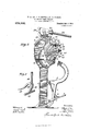
- FIG. 1 is a side elevation of our improved machine.
- Fig. 2 is a similar view partly in section.
- Fig. 3 is'a front elevation of the machine.
- Fig. 4 is a detail perspec tive view of the stationary welding die.
- Fig. 5 is a plan View of the same, showing a horseshoe in dotted lines in position to be provided with a toe-clip.
- Fig. .6 is a vertical section of the same on the line 66 of Fig. 5, and
- Fig. 7 is a detail perspective view of the gage.
- the front portion of the frame has formed on it projecting brackets 9 and 10, which carry the lower members of each pair of dies, for the heel and toe-calks respectively.
- the die 11 for the heel-calks is carried on a dieplate 12, normally held against a vertical Specification of Letters Patent.
- the cooperating die for turning the heel-calks is preferably in the form of a roller 14, pivotally supported in arms 15, which are in turn supported by links 16 and 17, pivoted on the frame, the pivotal connections of links 17 being carried by eccentries 18, for the purpose of permitting a vertical adjustment of the roller die 14.
- the other ends of said levers are connected to the shaft of a segmental gear 21, meshing with the toothed segment 2 and provided with side flanges 22 and a socket 23 for a handle 24. So far, the present machine does not differ materially from the machine of our said patent.
- the upper bracket 10 of the frame has an upstanding flange 25 at its outer edge, between which and a vertical face 26, formed near the inner end of said bracket, is adjustably mounted the die 27, engaged by the bolts 28, threaded in said flange 25, and held from lateral movement by plates 29, secured thereto by bolts 30.
- the frame runs back horizontally from said face 26 for a short distance, and carries the stud 31 and shearing-die 32. Said stud 31 is located at the upper edge of the face 26- in position to cooperate with the meohanism hereinafter described to form the usual recess and projection at the front of the shoe.
- curved arms 33 Pivoted on the frame and adjacent to the rear end of the toothed segment 2 are two curved arms 33, one on each side, which are connected in front of the frame to form a hammer-die 34.
- the flanges 22 of the gear 21 roll on the top surfaces of said arms 33, the said surfaces being so curved that said flanges will cam said arms downwardly as I further description. -as in the machine of our said patent.
- a coil spring 35 surrounds the pin .36 which connects the links 16 and arms 15, which spring tends to hold said arms in the position shown in Fig. 1.
- the gage which determines the vertical position 'of the shoe when in position to have a heelcalk turned.
- the gage proper or that part of it against which the heel of the shoe is placed, consists of a transverse bar 37, (see Fig. 7 carried by an arm 38, pivoted at 39 to a stem 40, adjustable vertically in an opening or socket, formed in or carried by an arm 41, pivoted to the frame on the same axis as the levers 19, said stem being clamped in adjusted position'by thumb-nut 42.
- the pin 36 which connects links 16 and arms 15, also passes through an opening formed in said arm 41, whereby the latter is swung up as the roller-die l moves forward to form a heel-calk and consequently raises the die out of the way of the roller-die in its reciprocations,
- the arm 38 which carries the gage 37 is extended beyond its pivot 39 in the form of a tailor arm 43, the end of which rests on the pivot which connects arms 15, links 20 andliiiks 17, wherebythe gage is swung on itsfpivot as the roller-die goes forward and is thereby further maintained out of the "path of the roller-die on its return travel.
Landscapes
- Engineering & Computer Science (AREA)
- Mechanical Engineering (AREA)
- Forging (AREA)
- Press Drives And Press Lines (AREA)
Description
W. H'. LEE, v]. T. SNOVER & M. H. PALMER. HORSESHOB OALKING' MACHINE. APPLICATION FILED MAB. B, 1916. 975,366 Patented Nov. 8, 1910.
s SHEETS-SHEET 1.
- anwntozs QXMW "H Lw, vmwmw mo m 1m: udnms PETERS 00., WASHINGTON, n. c,
W. H. LEE, V. T. SNOVER & M. H. PALMER.
HORSESHOE GALKING' MACHINE.
APPLICATION FILED MAILB, 1910.
f Patented Nov. 8, 1910.
3 SHEETS-SHEET 2.
vuzmlw c. THE NORRIS PETERS cm, wasmpmroq, n
W. H. LEE, V. T. S NOVER & M. H. PALMER.
I HORSESHOE GALKING MACHINE.
APPLICATION FILED MABHH, 1910.
Patented NOV. 8, 1910.
3 SHEETSBHEET 3.
s'rans A'rnn' QFFICE.
."WIIJJIAM I-I. LEE, VICTOR T. SNOVER, AND MILTON I-I. PALMER, 0F WYALUSING,
- PENNSYLVANIA.
HORSESI-IOE-CALKING MACHINE.
To all wh0 c it may concern:
Be it known that we, WILLIAM H. LEE, VICTOR T. SNovER, and MILTON H. PALMER, citizens of the United States, residing at Wyalusing, in the county of Bradford and State of Pennsylvania, have invented new and useful Improvements in Horseshoe-Call:- ing Machines, of which the following is a specification.
Our invention relates to machines for forming calks on horseshoes and consists in certain improvements which we have made to the machine of Patent No. 933,995, issued to us on September 14, 1909. The machine disclosed in the said patent was adapted for forming heel-calks only, whereas the present machine is provided with additional dies for welding on toe-calks, which dies do not require, however, any additional operating mechanism, the same manually-operable means actuating the movable members of both'the heel-calk and toe-calk dies.
Other improvements in the construction of the machine will be apparent upon reading the following detailed description in connection with the accompanying drawings, in which Figure 1 is a side elevation of our improved machine. Fig. 2 is a similar view partly in section. Fig. 3 is'a front elevation of the machine. Fig. 4 is a detail perspec tive view of the stationary welding die. Fig. 5 is a plan View of the same, showing a horseshoe in dotted lines in position to be provided with a toe-clip. Fig. .6 is a vertical section of the same on the line 66 of Fig. 5, and Fig. 7 is a detail perspective view of the gage.
In these views 1 is the frame, the curved upper portion of which carries the toothed segment 2, while to the lower portion thereof is pivoted the treadle 3, which actuates the lever 4, carrying the clamping-jaw 5. The depending cam-arm 6 of lever 4 has ratchet-teeth 7 formed on it, with which engages a pawl 8, pivoted on said treadle, to hold said jaw in clamping position.
The front portion of the frame has formed on it projecting brackets 9 and 10, which carry the lower members of each pair of dies, for the heel and toe-calks respectively. The die 11 for the heel-calks is carried on a dieplate 12, normally held against a vertical Specification of Letters Patent.
Application filed March 8, 1910.
Patented Nov. 8, 1910.
Serial No. 548,069.
shoulder on the bracket 9 by springs 13, exactly as in the machine of our said former patent. The cooperating die for turning the heel-calks is preferably in the form of a roller 14, pivotally supported in arms 15, which are in turn supported by links 16 and 17, pivoted on the frame, the pivotal connections of links 17 being carried by eccentries 18, for the purpose of permitting a vertical adjustment of the roller die 14. On the same axis as the frame-pivots of links 16, are pivoted levers 19, the ends of which are also connected, bylinks 20, to arms 15. The other ends of said levers are connected to the shaft of a segmental gear 21, meshing with the toothed segment 2 and provided with side flanges 22 and a socket 23 for a handle 24. So far, the present machine does not differ materially from the machine of our said patent.
The upper bracket 10 of the frame has an upstanding flange 25 at its outer edge, between which and a vertical face 26, formed near the inner end of said bracket, is adjustably mounted the die 27, engaged by the bolts 28, threaded in said flange 25, and held from lateral movement by plates 29, secured thereto by bolts 30. The frame runs back horizontally from said face 26 for a short distance, and carries the stud 31 and shearing-die 32. Said stud 31 is located at the upper edge of the face 26- in position to cooperate with the meohanism hereinafter described to form the usual recess and projection at the front of the shoe.
Pivoted on the frame and adjacent to the rear end of the toothed segment 2 are two curved arms 33, one on each side, which are connected in front of the frame to form a hammer-die 34. The flanges 22 of the gear 21 roll on the top surfaces of said arms 33, the said surfaces being so curved that said flanges will cam said arms downwardly as I further description. -as in the machine of our said patent.
which the stud 31 enters to form the usual recess and projection at the front of the shoe. A coil spring 35 surrounds the pin .36 which connects the links 16 and arms 15, which spring tends to hold said arms in the position shown in Fig. 1.
There only remains to be described the gage which determines the vertical position 'of the shoe when in position to have a heelcalk turned. The gage proper, or that part of it against which the heel of the shoe is placed, consists of a transverse bar 37, (see Fig. 7 carried by an arm 38, pivoted at 39 to a stem 40, adjustable vertically in an opening or socket, formed in or carried by an arm 41, pivoted to the frame on the same axis as the levers 19, said stem being clamped in adjusted position'by thumb-nut 42. The pin 36, which connects links 16 and arms 15, also passes through an opening formed in said arm 41, whereby the latter is swung up as the roller-die l moves forward to form a heel-calk and consequently raises the die out of the way of the roller-die in its reciprocations,
The arm 38, which carries the gage 37 is extended beyond its pivot 39 in the form of a tailor arm 43, the end of which rests on the pivot which connects arms 15, links 20 andliiiks 17, wherebythe gage is swung on itsfpivot as the roller-die goes forward and is thereby further maintained out of the "path of the roller-die on its return travel.
The operation of forming the heel-calks will be understood from the above without It is precisely the same Each time" the handle 241 is pulled forward to actuate the roller-die, the hammer-die 34 is also brought down and, when the heel of a shoe is too long, it may be sheared off between the rear edge of said ha1nmerdie and the shearing-die 32. To apply a toe-calk, it
is temporarily secured to the shoe as usual,
brought to a welding-heat and placed in the die 27, as shown in Figs. 1 and 6. The hammer-die is then brought down and Welds the calk and shoe together, the stud 31 forming the usual clip on the front of the calk.
with to form h el-calks, a toothed segment on said frame, a segmental flanged gear meshing therewith, an arm connected tosaid gear whereby it may be caused to roll on said segment, levers pivoted to the frame and to said gear and links connecting said levers to said roller-die, a second stationary die on said frame above said roller-die, arms pivoted to the frame and having a hammerdie at their free ends, the top surfaces of said arms constituting cams on which the flanges of said gear roll and thereby actuate said hammer-die.
2. In a machine for calking horseshoes, the combination with the frame, a die thereon and means to clamp a horseshoe in proper position relatively to said die, of levers pivoted on each side of said frame, arms'c'arrying a roller-die and connected to said levers and to said frame by links, so that the swinging of said levers will cause said roller'die to move forward and backward 'over said first mentioned die, an arm pivoted to the frame and to the arms carry- WILLIAM H. LEE. VICTOR T. SNOVER. MILTON H. PALMER.
Vitnesses:
C. I. VAN DYKE, SCOVILLE Arms.
Priority Applications (1)
| Application Number | Priority Date | Filing Date | Title |
|---|---|---|---|
| US54806910A US975366A (en) | 1910-03-08 | 1910-03-08 | Horseshoe-calking machine. |
Applications Claiming Priority (1)
| Application Number | Priority Date | Filing Date | Title |
|---|---|---|---|
| US54806910A US975366A (en) | 1910-03-08 | 1910-03-08 | Horseshoe-calking machine. |
Publications (1)
| Publication Number | Publication Date |
|---|---|
| US975366A true US975366A (en) | 1910-11-08 |
Family
ID=3043745
Family Applications (1)
| Application Number | Title | Priority Date | Filing Date |
|---|---|---|---|
| US54806910A Expired - Lifetime US975366A (en) | 1910-03-08 | 1910-03-08 | Horseshoe-calking machine. |
Country Status (1)
| Country | Link |
|---|---|
| US (1) | US975366A (en) |
-
1910
- 1910-03-08 US US54806910A patent/US975366A/en not_active Expired - Lifetime
Similar Documents
| Publication | Publication Date | Title |
|---|---|---|
| US975366A (en) | Horseshoe-calking machine. | |
| US1354770A (en) | Apparatus for manufacturing vehicle bumper-bars | |
| US482962A (en) | Machine for edge-curling sheet metal | |
| US933995A (en) | Machine for forming calks on horseshoes and for sharpening such calks. | |
| US1031605A (en) | Sheet-metal-working machine. | |
| US1718265A (en) | Bolt-heading machine | |
| US712229A (en) | Saw-setting machine. | |
| US1119376A (en) | Work-holder. | |
| US1619537A (en) | Spring-eye bender | |
| US36878A (en) | Improvement in machines for making brace-jaws for steam-boilers | |
| US1441047A (en) | Machine for bending metal | |
| US189322A (en) | Improvement in horseshoe-machines | |
| US710231A (en) | Veneer-bending machine. | |
| US536780A (en) | Nipper-jaw for lasting-machines | |
| US3681A (en) | reynolds | |
| US1417294A (en) | Gripping device | |
| US358408A (en) | Wire-nail machine | |
| US508544A (en) | Thirds to william pl stanley and herdman mckay | |
| US1254398A (en) | Snathe-press. | |
| US1126626A (en) | Machine for shaping prepared blanks in the manufacture of horseshoes. | |
| US1048612A (en) | Crimping-machine. | |
| US1581182A (en) | Mold-slide safety device | |
| US1009823A (en) | Machine for making wire corset-stays. | |
| US2063969A (en) | Forging machine | |
| US1316310A (en) | larsen |