US975229A - Flying-machine. - Google Patents
Flying-machine. Download PDFInfo
- Publication number
- US975229A US975229A US52939209A US1909529392A US975229A US 975229 A US975229 A US 975229A US 52939209 A US52939209 A US 52939209A US 1909529392 A US1909529392 A US 1909529392A US 975229 A US975229 A US 975229A
- Authority
- US
- United States
- Prior art keywords
- planes
- carrying
- beating
- machine
- secured
- Prior art date
- Legal status (The legal status is an assumption and is not a legal conclusion. Google has not performed a legal analysis and makes no representation as to the accuracy of the status listed.)
- Expired - Lifetime
Links
- 238000010009 beating Methods 0.000 description 22
- 239000011435 rock Substances 0.000 description 11
- 230000001154 acute effect Effects 0.000 description 2
- 210000005069 ears Anatomy 0.000 description 2
- 239000004744 fabric Substances 0.000 description 2
- 239000002184 metal Substances 0.000 description 2
- ATJFFYVFTNAWJD-UHFFFAOYSA-N Tin Chemical compound [Sn] ATJFFYVFTNAWJD-UHFFFAOYSA-N 0.000 description 1
- 238000010276 construction Methods 0.000 description 1
- 230000005484 gravity Effects 0.000 description 1
Images


Classifications
-
- B—PERFORMING OPERATIONS; TRANSPORTING
- B64—AIRCRAFT; AVIATION; COSMONAUTICS
- B64C—AEROPLANES; HELICOPTERS
- B64C33/00—Ornithopters
- B64C33/02—Wings; Actuating mechanisms therefor
Definitions
- This invention has relation to certain new
- the object of my invention is to provide a flying machine with oppositely located beating planes, with connecting, vibrating guiding or carrying planes, and two connected fin planes actuated by said carrying planes.
- Another object is to provide a flying main spaced relation in a common plane and connected by means of two hinged'ly secured upwardlydirected fin planes, said fin planes being normally held at an acute angle to one another and provided with valves automatically closed on the down stroke of said
- a still further object is to provide a flying machine with two connected carrying planes arranged to vibrate in a horizontal position away from and toward one another.
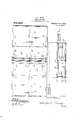
- Faigure 1 shows an end elevation of a flying machine embodying my invention.
- Fig. 2 shows a transverse sectional view through the carrying plane and one of the connected valves.
- Fig. 3 shows a top view of the machine.
- Fig. 4 shows a view disclosing the carrying and tin planes in their lowered condition.
- Fig. 5 is a side elevation of one of the beating planes.
- the numeral 5 designates the base frame members, 6 the standards, 7 the top bars and 8 and 9 the connecting sills.
- the rectangular supporting frame thus formed is of any suitable length, and the standards 6 are of a height permitting the carrying of suitable passengers and machmery' in the top and bottom frame members.
- bearing ears 10 Secured to the standards 6 at their upper ends, are the bearing ears 10, carrying the pins 11, which pins in turn give suitable support to the beating planes 12 which are of any approved construction and are preferably provided with curved under surfaces, as disclosed.
- beating planes are shown as each provided with an extending rib 13, to which rib are secured the ears 14 carrying the pins 4, which pivotally support the upper ends of the operating arms 15, which arms are secured to the bar 3 actuated by the machine head 17,1eciprocated by means of the engine 19, the head 17 being guided upon the rod 18.
- the connected beating planes are actuated.
- rock bars 20 Secured to the transverse top members 7 by means of the pins 2, are the rock bars 20, which at their upper ends by means of the pins 21 carry the rods 22, which rods at their opposite ends by means of the pins 23 are connected to the beating planes 12.
- These rods 22 are covered by means of a fabric or sheet metal to form supporting gliding orcarrying planes 25 arranged to vibrate in a horizontal position synchronously with the beating planes.
- the rock bars 20 are disposed in two lines, these bars being held in spaced relation in sets of two, so that a space is formed centrally of the machine which is not covered by the carrying or gliding planes.
- Each set of rock arms 20 is connected by means of a helical spring 26, which tends to normally draw the carrying planes toward one another.
- Hinged to the pins 21, are the bars which at their upper ends, by means of the pins 31, are secured to the rib 33, these bars 30 also being covered with a cloth or metal to form two upstanding fin planes, which converge toward one another and are at rest held at an acute angle to one another.
- the rib 33 has suitable openings which are covered by means of the hood 35 so arranged that when the carrying planes are carried downward to their full limit the hood 35 contacts with the fin planes 30 and so closes the escape openings within the rib.
- the supporting area of the machine is very materially increased on the down stroke of the carrying plane in thatthe fin planes are carried from an approximately vertical position into a horizontal position.
- valve and .cap The operation of the valve and .cap is to allow for the free escape of air at a point directly above the center of gravity of the machine, thereby increasing the stability of the machine.
- These carrying planes serve as a covering for the machine, as well in the capacity of wings.
- a machine constructed according to my invention is both durable and efiicient in operation.
- a suitable frame oppositely positioned beating planesmovably secured-to said frame, a plurality of oppositely positioned pivotally held rock bars, horizontally held carrying planes pivotally secured to each beating plane and to said rock bars, and two connected fin planes secured to said carrying planes.
- a suitable frame oppositely positioned'beating planes pivoted to the upper ends of said frame, means to synchronously actuate said beating planes, a plurality of oppositely positioned rock bars held in spaced relation and centrally between said beating planes, horizontally held carrying planes pivotally secured to each beatlng planeand to the nearest rock bars, and two connected'upstanding fin planes secured at their lower edges to said carrying planes.
- a suitable frame oppositely positioned beating planes, means to actuate said beating planes, a plurality of oppositely positioned rock bars, horizontally held carrying planes secured to each beating plane and carried by said rock bars, two connected upstanding fin planes secured at their lower edges to said carrying plane and means for resiliently connecting carrymg planes.
- beating planes oppositely positioned beating planes,.means to actuate said beating planes, a plurality of oppositely positioned pivotally held rock bars held in spaced relationand centrally between said beating planes, a horizontally held vibrating carrying plane pivotally secured to each of the beating planes and to the nearest rock'bar, two connected upstanding fin planes secured at their lower edges to said carrying frame, and valves carried by said fin planes and arranged to close on the down stroke of said fin planes.
- two horizontally disposed carrying planes active through small arcs and adapted to travel in opposite direc tions, fin planes connected to said carrying planes, and beating planes for actuating said carrying planes.
- a suitable frame oppositely located beating planes, movably secured to said frame, means to actuate said oscoe e. GORE.
Landscapes
- Engineering & Computer Science (AREA)
- Aviation & Aerospace Engineering (AREA)
- Percussion Or Vibration Massage (AREA)
Description
wwww R. 0. GORE.
FLYING MACHINE. APPLICATION III IID NOV. 22, 1909. 975,229. Patented Now-8,1910.
3 BHEET S-SHEET 1:
awe/whom 2. a Gm,
R. G. GORE.
FLYING MACHINE.
APPLICATION FILED NOV. 22, 1909.
Patented Nov. 8, 1910.
3 SHEETS-SHEET 2.
L TM \N,
Witmcooco v R. U. GORE.
FLYING MACHINE.
APPLICATION nun NOV; 22, 1909.
I and useful improvcments'in flying machines.
chine with vibrating carrying planes held fin planes.
FFICE.
EOSOOE C. GORE, E TECUMSEH, NEBRASKA.
FLYING-MACHINE.
Specification of Letters Patent.
Patented Nov. 8, 1910.
Application filed November 22, 1909. Serial No. 529,392.
To all whom it may concern:
Be it known that I, Rosoon C. Gone, a citizen of the United States, residing at Tecumseh, in the county of Johnson and State of Nebraska, have invented certain new and useful Improvements in Flying- Machines, of which the following is a specification.
This invention has relation to certain new The object of my invention is to provide a flying machine with oppositely located beating planes, with connecting, vibrating guiding or carrying planes, and two connected fin planes actuated by said carrying planes.
Another object is to provide a flying main spaced relation in a common plane and connected by means of two hinged'ly secured upwardlydirected fin planes, said fin planes being normally held at an acute angle to one another and provided with valves automatically closed on the down stroke of said A still further object is to provide a flying machine with two connected carrying planes arranged to vibrate in a horizontal position away from and toward one another.
VViththe above and other objects in view the present invention consists in the combination and arrangement of parts as will be hereinafter more full described and particularly'pointed out in the. appended claims, it being understood that changes in the specific structure shown and described may be made within the scope of the claims without departing from the spirit of the invention.
In "the drawings forming a part of this specification, and in which like numerals of reference indicate similar parts in the several views, Faigure 1 shows an end elevation of a flying machine embodying my invention. Fig. 2 shows a transverse sectional view through the carrying plane and one of the connected valves. Fig. 3 shows a top view of the machine. Fig. 4 shows a view disclosing the carrying and tin planes in their lowered condition. Fig. 5 is a side elevation of one of the beating planes.
In the accompanying drawings the numeral 5 designates the base frame members, 6 the standards, 7 the top bars and 8 and 9 the connecting sills. The rectangular supporting frame thus formed is of any suitable length, and the standards 6 are of a height permitting the carrying of suitable passengers and machmery' in the top and bottom frame members.-
Secured to the standards 6 at their upper ends, are the bearing ears 10, carrying the pins 11, which pins in turn give suitable support to the beating planes 12 which are of any approved construction and are preferably provided with curved under surfaces, as disclosed.
In the drawings the beating planes are shown as each provided with an extending rib 13, to which rib are secured the ears 14 carrying the pins 4, which pivotally support the upper ends of the operating arms 15, which arms are secured to the bar 3 actuated by the machine head 17,1eciprocated by means of the engine 19, the head 17 being guided upon the rod 18. As the head 17 reciprocates in a vertical plane the connected beating planes are actuated.
Secured to the transverse top members 7 by means of the pins 2, are the rock bars 20, which at their upper ends by means of the pins 21 carry the rods 22, which rods at their opposite ends by means of the pins 23 are connected to the beating planes 12. These rods 22 are covered by means of a fabric or sheet metal to form supporting gliding orcarrying planes 25 arranged to vibrate in a horizontal position synchronously with the beating planes. As shown in the drawings, the rock bars 20 are disposed in two lines, these bars being held in spaced relation in sets of two, so that a space is formed centrally of the machine which is not covered by the carrying or gliding planes.
Each set of rock arms 20 is connected by means of a helical spring 26, which tends to normally draw the carrying planes toward one another.
Hinged to the pins 21, are the bars which at their upper ends, by means of the pins 31, are secured to the rib 33, these bars 30 also being covered with a cloth or metal to form two upstanding fin planes, which converge toward one another and are at rest held at an acute angle to one another.
The rib 33 has suitable openings which are covered by means of the hood 35 so arranged that when the carrying planes are carried downward to their full limit the hood 35 contacts with the fin planes 30 and so closes the escape openings within the rib.
Y neath the fin planes on their upstroke.
From the foregoing it will be seen that the supporting area of the machine is very materially increased on the down stroke of the carrying plane in thatthe fin planes are carried from an approximately vertical position into a horizontal position.
The operation of the valve and .cap is to allow for the free escape of air at a point directly above the center of gravity of the machine, thereby increasing the stability of the machine. These carrying planes serve as a covering for the machine, as well in the capacity of wings. The planes 25, how
ever, are active in a very small are, in comparison to that of the beating planes. it is, of course, understood that the motive power is supplied to the planes through the engine 19.
A machine constructed according to my invention is both durable and efiicient in operation.
Having thus described my said invention,
.what is claimed is:
1. In a flying machine, a suitable frame, oppositely positioned beating planesmovably secured-to said frame, a plurality of oppositely positioned pivotally held rock bars, horizontally held carrying planes pivotally secured to each beating plane and to said rock bars, and two connected fin planes secured to said carrying planes.
2. In a flying machine, a suitable frame, oppositely positioned'beating planes pivoted to the upper ends of said frame, means to synchronously actuate said beating planes, a plurality of oppositely positioned rock bars held in spaced relation and centrally between said beating planes, horizontally held carrying planes pivotally secured to each beatlng planeand to the nearest rock bars, and two connected'upstanding fin planes secured at their lower edges to said carrying planes.
'3. In a flying machine, a suitable frame, oppositely positioned beating planes, means to actuate said beating planes, a plurality of oppositely positioned rock bars, horizontally held carrying planes secured to each beating plane and carried by said rock bars, two connected upstanding fin planes secured at their lower edges to said carrying plane and means for resiliently connecting carrymg planes.
l. In a flying machine, a suitable frame,
oppositely positioned beating planes,.means to actuate said beating planes, a plurality of oppositely positioned pivotally held rock bars held in spaced relationand centrally between said beating planes, a horizontally held vibrating carrying plane pivotally secured to each of the beating planes and to the nearest rock'bar, two connected upstanding fin planes secured at their lower edges to said carrying frame, and valves carried by said fin planes and arranged to close on the down stroke of said fin planes. y 5. In combination, two horizontally disposed carrying planes active through small arcs and adapted to travel in opposite direc tions, fin planes connected to said carrying planes, and beating planes for actuating said carrying planes.
6. In a flying machine, a suitable frame, oppositely located beating planes, movably secured to said frame, means to actuate said oscoe e. GORE.
Witnesses:
JoHN WARD, J. E. HARDIN.
Priority Applications (1)
| Application Number | Priority Date | Filing Date | Title |
|---|---|---|---|
| US52939209A US975229A (en) | 1909-11-22 | 1909-11-22 | Flying-machine. |
Applications Claiming Priority (1)
| Application Number | Priority Date | Filing Date | Title |
|---|---|---|---|
| US52939209A US975229A (en) | 1909-11-22 | 1909-11-22 | Flying-machine. |
Publications (1)
| Publication Number | Publication Date |
|---|---|
| US975229A true US975229A (en) | 1910-11-08 |
Family
ID=3043608
Family Applications (1)
| Application Number | Title | Priority Date | Filing Date |
|---|---|---|---|
| US52939209A Expired - Lifetime US975229A (en) | 1909-11-22 | 1909-11-22 | Flying-machine. |
Country Status (1)
| Country | Link |
|---|---|
| US (1) | US975229A (en) |
-
1909
- 1909-11-22 US US52939209A patent/US975229A/en not_active Expired - Lifetime
Similar Documents
| Publication | Publication Date | Title |
|---|---|---|
| US1196682A (en) | Brake for marine vessels. | |
| US281216A (en) | White | |
| US1410951A (en) | Machine for removing the skins from the kernels of nuts | |
| US852239A (en) | Air-ship. | |
| US1781323A (en) | Current collector for electric railways | |
| CN110438770A (en) | Clothes hanger drying system and clothes hanger dries in air | |
| US1011139A (en) | Aeroplane. | |
| US1794402A (en) | Suspension for centrifugal extractors | |
| US1533786A (en) | Wing control for flying machines and safety device therefor | |
| US910683A (en) | Air-ship. | |
| US1755124A (en) | Airplane control stick | |
| US1040785A (en) | Aeroplane. | |
| US2254576A (en) | Oscillating chaff raiser | |
| US374754A (en) | Elevating-bolt | |
| US1154214A (en) | Flying-machine. | |
| US1121616A (en) | Parachute. | |
| US1034257A (en) | Aeroplane. | |
| US1379621A (en) | Gate | |
| US1185166A (en) | Safety attachment for elevator-shafts. | |
| US492032A (en) | Device for grading broom-corn stems | |
| US1163231A (en) | Aeroplane. | |
| US890421A (en) | Trolley-wheel support. | |
| US532875A (en) | Pelting-machine | |
| US957919A (en) | Clothes-pounder. | |
| US1370902A (en) | Airship |