US975117A - Walking traction-wheel. - Google Patents
Walking traction-wheel. Download PDFInfo
- Publication number
- US975117A US975117A US51792509A US1909517925A US975117A US 975117 A US975117 A US 975117A US 51792509 A US51792509 A US 51792509A US 1909517925 A US1909517925 A US 1909517925A US 975117 A US975117 A US 975117A
- Authority
- US
- United States
- Prior art keywords
- levers
- wheel
- rocking
- lever
- feet
- Prior art date
- Legal status (The legal status is an assumption and is not a legal conclusion. Google has not performed a legal analysis and makes no representation as to the accuracy of the status listed.)
- Expired - Lifetime
Links
- 230000033001 locomotion Effects 0.000 description 18
- 238000010276 construction Methods 0.000 description 4
- 239000011435 rock Substances 0.000 description 2
- 230000015572 biosynthetic process Effects 0.000 description 1
- 230000008933 bodily movement Effects 0.000 description 1
- 238000006073 displacement reaction Methods 0.000 description 1
- 238000005096 rolling process Methods 0.000 description 1
- 239000007787 solid Substances 0.000 description 1
Images

Classifications
-
- B—PERFORMING OPERATIONS; TRANSPORTING
- B60—VEHICLES IN GENERAL
- B60B—VEHICLE WHEELS; CASTORS; AXLES FOR WHEELS OR CASTORS; INCREASING WHEEL ADHESION
- B60B15/00—Wheels or wheel attachments designed for increasing traction
- B60B15/18—Wheels with ground-engaging plate-like shoes
Definitions
- a further object of my invention is to provide a. new and improved arrangement for interconnection with feet for operaand operating wholly through lcv r connection.
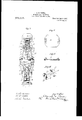
- Figure 1 is a side elevation with parts in section;
- Fig. 2 is a. similar view with )arts in sli htl r dverent )osition and F 1g. 8 1s a the wheel rolling on an incline; central vertical section through and Figs. 4, 5, and 6 are details.
- 10 indicates in general a hub of any desired construction having side flanges, 11, preferably of star formation for lightness and for accessibility of the supported parts.
- the hub is provided with series of spokes, 12, which afford support to a rim member, 13, beyond which stand a. series of feet, 15.
- Each foot, 15, has connected thereto, for pivotal movement on a transverse axis.
- the legs, 16, of adjacent feet, constituting a pair are con nected to a common rocking member, 18, which may communicate pressure from one foot ito the other of the pair, forcing one foot outward as the other is forced inward the wheel nermost position, extends by the action of the Wheel ing of saidlever.
- each lever 18 is mounted for radial motion with respect to the flanges 11-l1 of the rim, as "Well as for rocking motion, and to this end I have shown each lever 18 as provided with longitudinal slot, 19, fitting overa pin, 20, mounted between points of the flanges.
- the inner end of each lever 18 is expandedintoa transverse head, 21, to opposite extremities of which on opposite sides of the median line of the lever the legs 16 are pivotally connected.
- Said lever when in its inpreferably substantially an equal distance on each side of the said pivotahsnpport 20, and the outer end of the lever is likewise expanded into an outer head 22, hearing in its extremities pins proximate pins 23 of the several owing to the rock- .40, levers throughout the wheel lacing interconnected h'v neans of links, 24, the arrange ment of the heads 22 and pins 23 being-prefl era-lily such that when all levers 18 stand in their radially innermost posit-ions of movement, the pins 23 are separated by distances equal to the chords between the pivotal points 20-20, and the links 24 have slot en 'agement with the pins, as at 25, such that a solid body of the link equal to the aforesaid chord-length is interposed between the pins of each two adjacent rocking levers.
- the slots 25 ailord such a play as to accommodate the action shown in Fig.
- a lever 18 swings over to one side, While in its innermostradial position, it may impart an equal degree of movement to the next adjacent member on the side toward which its outer end swings, provided that lever be also in its radially innermost position as a result'of pressure upon one of its feet.
- the slot arrangement also provides that if one lever is at its radially innermost posit-ion and the adjacent lever is at its .tates, the interconnection between the rockmovement will rock as the wheel rotates, the
- a traction wheel the combination of a hub, a plurality of rocking levers connected with said hub for radial displacement relative thereto and for rocking movement, means for normally holding said levers at their outer limits of radial.movement, legs connected to said levers for movement inward or outward with the rocking of the levers, and lost motion link connections between the levers.
- a traction wheel the combination of a hub, a plurality of rocking levers mounted thereon for bodily movement inwardly or outwardly and for rocking;movement when in'their inward position, legs connected to one end of the levers on opposite sides of the median line thereof for gencrallyradiah movement in response to rocking movement,
- a traction wheel the combination of a hub, pivot pins mounted on said hub, rocking levers upon said pins having radial slots therein whereby the levers may move radially upon the pins, means normally holding said levers at their outermost position, legs connected to the inner ends of said levers on opposite sides of the median lines thereof, and lost motion link connections between the outer ends of said levers throughout the series of levers.
Landscapes
- Engineering & Computer Science (AREA)
- Mechanical Engineering (AREA)
- Orthopedics, Nursing, And Contraception (AREA)
Description
I s. M. BfOWER. WALKING TRACTION WHEEL.
APPLICATION FILED SEPT. 15, 1909.
Fig.1
Patented Nov. 8, 1910.
' 2 SHEETS-SHEET l.
S. M. BOWERT WALKING TRACTION WHEEL.
' APPLICATION IILBIJ SEPT.15, 1909.
Patented Nov. 8, 1910.
' eraloly guided in their tion, dispensing with gearing UNITED snares w PATENT canton.
SAMUEL BOWER, OF CHICAGO, ILLINUIS.
WALKING TRACTION-UIHEEL Specification of Letters Patent.
Application filed September 15, 1809. Serial No. 517,825.
lb all whom it may concern:
Be it known that I, SAMUEL M. Bowen, a citizen of the United States, residing at Chicago, in the county of Cool: and State of Illinois, have invented certain new and useful" Improvements in \Vallring Traction- WVhecls, of which the following is a specifi- -cry of the Wheel interrelated for the constant"presentation oi: two or more to-the ground atoll times and constructed. so that only. the-parts connected to the feet which are under pressurework or move, all other parts remaining substantially stationary until called into play.
A further object of my invention is to provide a. new and improved arrangement for interconnection with feet for operaand operating wholly through lcv r connection.
Tn/the embodiment of my invention shown, Figure 1 is a side elevation with parts in section; Fig. 2 is a. similar view with )arts in sli htl r diilerent )osition and F 1g. 8 1s a the wheel rolling on an incline; central vertical section through and Figs. 4, 5, and 6 are details.
In the construction shown, 10 indicates in general a hub of any desired construction having side flanges, 11, preferably of star formation for lightness and for accessibility of the supported parts. The hub is provided with series of spokes, 12, which afford support to a rim member, 13, beyond which stand a. series of feet, 15. Each foot, 15, has connected thereto, for pivotal movement on a transverse axis. two legs, 16, prefmovomont with respect to the rim, as by links 17, at one end pivotally connected to the legs, and at the other end connected to :1v fitting, 17, on the rim. At their inner extremities the legs, 16, of adjacent feet, constituting a pair, are con nected to a common rocking member, 18, which may communicate pressure from one foot ito the other of the pair, forcing one foot outward as the other is forced inward the wheel nermost position, extends by the action of the Wheel ing of saidlever.
It especially desirable that only the rocking members connected with the feet in play orunder pressure should work or rock, all others remaining stationary, and as a simple means of attaining such end, 1 provide a construction as follows; Each. lever 18 is mounted for radial motion with respect to the flanges 11-l1 of the rim, as "Well as for rocking motion, and to this end I have shown each lever 18 as provided with longitudinal slot, 19, fitting overa pin, 20, mounted between points of the flanges. The inner end of each lever 18 is expandedintoa transverse head, 21, to opposite extremities of which on opposite sides of the median line of the lever the legs 16 are pivotally connected. Said lever, when in its inpreferably substantially an equal distance on each side of the said pivotahsnpport 20, and the outer end of the lever is likewise expanded into an outer head 22, hearing in its extremities pins proximate pins 23 of the several owing to the rock- .40, levers throughout the wheel lacing interconnected h'v neans of links, 24, the arrange ment of the heads 22 and pins 23 being-prefl era-lily such that when all levers 18 stand in their radially innermost posit-ions of movement, the pins 23 are separated by distances equal to the chords between the pivotal points 20-20, and the links 24 have slot en 'agement with the pins, as at 25, such that a solid body of the link equal to the aforesaid chord-length is interposed between the pins of each two adjacent rocking levers. The slots 25 ailord such a play as to accommodate the action shown in Fig.
1, that is to say, such that one lever 18 may,
for the pins I v he moved radially inward over to its greatcst angle to a radial line without disturbing the position of theadjacent rocking lever on the side toward which the inner end of the first said lever is moved. Obviously, however, a lever 18 swings over to one side, While in its innermostradial position, it may impart an equal degree of movement to the next adjacent member on the side toward which its outer end swings, provided that lever be also in its radially innermost position as a result'of pressure upon one of its feet. The slot arrangement also provides that if one lever is at its radially innermost posit-ion and the adjacent lever is at its .tates, the interconnection between the rockmovement will rock as the wheel rotates, the
radially outermost position, asshown in the extreme right of Fig. 1, tilting of the inwardly positioned lever to throw its outer end toward theadjacent outwardly positioned lever, does not affect the latter but. only takes up the lost motion of the two slots 25 in the conneetingdink endsw By this arrangement'all the levers 18 remain at rest, save those connected with the feet which have been put under pressure. Springs 28 are provided in suitable arrangement for holding the several levers normally in their radially outermost position, and the feet are preferably constructed as shown in Fig. 4 and Fig. 5 in plate form with depending flange.
It will be observed that, as the wheel roing levers 18 insures that at least two feet wlll always be in contact with the ground with the lever or levers appurtenant thereto moved radially inward and in play, but that the balance of the rocking levers will be unaffected by the movements of those in play. As a result only the feet connected with the rocking levers wl'nch are in plavo'r under balance of the feet standing in the mid posi tion to which they are thrown by the outward movement of the rocking levers.
While I have herein described in some detail a particular embodiment of my invention, it will be apparent to those skilled in the art that changes might be made in the details of construction without departure from the spirit and scope of the invention and within the scope of the appended claims.
\Vhat I claim is: I
" 1. In atracti-on wheel, the combination of a hub,a plurality of rocking members thereon, feet operatively associated with .said rocking members, and connections'between the adjacent rocking members to .eflect positive movement in harmony of those feet i which stand under pressure, arranged to leave idle orstill the rocking members con nected to feet not under pressure.
2. IIl a traction wheel, the combination of a hub, a plurality of rocking levers connected with said hub for radial displacement relative thereto and for rocking movement, means for normally holding said levers at their outer limits of radial.movement, legs connected to said levers for movement inward or outward with the rocking of the levers, and lost motion link connections between the levers.
3. In a traction wheel, the combination of a hub, a plurality of rocking levers mounted thereon for bodily movement inwardly or outwardly and for rocking;movement when in'their inward position, legs connected to one end of the levers on opposite sides of the median line thereof for gencrallyradiah movement in response to rocking movement,
of the levers, and lost motion link connections between the ends of the levers opposite the leg connections.
4. In a traction wheel, the combination of a hub, rocking levers connected to said hub, legs connected to points at one end of each of said levers on opposite sides of the median line, feet connected to the ends of said legs, guiding .means for the outer ends of said legs, and links connecting the end of each lever with the two levers next adjacent thereto throughout the series of levers.
5. In a traction wheel, the combination of a hub, pivot pins mounted on said hub, rocking levers upon said pins having radial slots therein whereby the levers may move radially upon the pins, means normally holding said levers at their outermost position, legs connected to the inner ends of said levers on opposite sides of the median lines thereof, and lost motion link connections between the outer ends of said levers throughout the series of levers.
In testimony whereof I hereunto set my hand in the presence of two witnesses.
SAMUEL M. BOlVER. In the presence of-- \V, Lixiv ALLEN, MARY F. ALLEN.
(iii
Priority Applications (1)
| Application Number | Priority Date | Filing Date | Title |
|---|---|---|---|
| US51792509A US975117A (en) | 1909-09-15 | 1909-09-15 | Walking traction-wheel. |
Applications Claiming Priority (1)
| Application Number | Priority Date | Filing Date | Title |
|---|---|---|---|
| US51792509A US975117A (en) | 1909-09-15 | 1909-09-15 | Walking traction-wheel. |
Publications (1)
| Publication Number | Publication Date |
|---|---|
| US975117A true US975117A (en) | 1910-11-08 |
Family
ID=3043496
Family Applications (1)
| Application Number | Title | Priority Date | Filing Date |
|---|---|---|---|
| US51792509A Expired - Lifetime US975117A (en) | 1909-09-15 | 1909-09-15 | Walking traction-wheel. |
Country Status (1)
| Country | Link |
|---|---|
| US (1) | US975117A (en) |
Cited By (4)
| Publication number | Priority date | Publication date | Assignee | Title |
|---|---|---|---|---|
| US2664962A (en) * | 1951-08-15 | 1954-01-05 | Faszczuk Roman | Automotive sleigh |
| US5380075A (en) * | 1994-02-23 | 1995-01-10 | Haws; Spencer K. | Footed wheel for irrigation apparatus |
| US9272571B2 (en) * | 2014-02-27 | 2016-03-01 | Tommy No Trax, LLC | Drive wheel assembly for self-propelled irrigation system |
| US20190030950A1 (en) * | 2013-03-15 | 2019-01-31 | X-Sim Llc | Segmented wheel and method and system for controlling a segmented wheel |
-
1909
- 1909-09-15 US US51792509A patent/US975117A/en not_active Expired - Lifetime
Cited By (5)
| Publication number | Priority date | Publication date | Assignee | Title |
|---|---|---|---|---|
| US2664962A (en) * | 1951-08-15 | 1954-01-05 | Faszczuk Roman | Automotive sleigh |
| US5380075A (en) * | 1994-02-23 | 1995-01-10 | Haws; Spencer K. | Footed wheel for irrigation apparatus |
| US20190030950A1 (en) * | 2013-03-15 | 2019-01-31 | X-Sim Llc | Segmented wheel and method and system for controlling a segmented wheel |
| US10906352B2 (en) * | 2013-03-15 | 2021-02-02 | X-Sim Llc | Segmented wheel and method and system for controlling a segmented wheel |
| US9272571B2 (en) * | 2014-02-27 | 2016-03-01 | Tommy No Trax, LLC | Drive wheel assembly for self-propelled irrigation system |
Similar Documents
| Publication | Publication Date | Title |
|---|---|---|
| US727720A (en) | Traveling stairway. | |
| US1242759A (en) | Resilient wheel. | |
| US151841A (en) | Improvement in sewing-machine-caster platforms | |
| US539672A (en) | Fire escape and tower | |
| US1072284A (en) | Pedal-propelled vehicle. | |
| US1073449A (en) | Merry-go-round. | |
| US241395A (en) | Velocipede | |
| US1165726A (en) | Resilient wheel. | |
| US1010537A (en) | Merry-go-round. | |
| US130892A (en) | Improvement in traction-wheels | |
| US1152318A (en) | Landing-chair for elevators. | |
| US359098A (en) | Expansion wheel | |
| US647244A (en) | Automobile vehicle. | |
| US1297259A (en) | Traction-wheel. | |
| US104580A (en) | Improvement in car-trucks | |
| US1038835A (en) | Traction-wheel. | |
| US1193840A (en) | stahle | |
| US122107A (en) | Improvement in treadle for sewing-machines | |
| US458596A (en) | Horse-power | |
| US253286A (en) | Man-power | |
| US496245A (en) | Car-brake | |
| US1721769A (en) | Traction wheel | |
| US1124350A (en) | Resilient wheel. | |
| US366331A (en) | Mechanical movement | |
| US104595A (en) | peters |