US9746136B2 - Illumination device having multiple LED elements with varying color temperatures - Google Patents
Illumination device having multiple LED elements with varying color temperatures Download PDFInfo
- Publication number
- US9746136B2 US9746136B2 US12/685,069 US68506910A US9746136B2 US 9746136 B2 US9746136 B2 US 9746136B2 US 68506910 A US68506910 A US 68506910A US 9746136 B2 US9746136 B2 US 9746136B2
- Authority
- US
- United States
- Prior art keywords
- light
- emitting devices
- illumination device
- color temperature
- emitting
- Prior art date
- Legal status (The legal status is an assumption and is not a legal conclusion. Google has not performed a legal analysis and makes no representation as to the accuracy of the status listed.)
- Active, expires
Links
Images


Classifications
-
- F—MECHANICAL ENGINEERING; LIGHTING; HEATING; WEAPONS; BLASTING
- F21—LIGHTING
- F21K—NON-ELECTRIC LIGHT SOURCES USING LUMINESCENCE; LIGHT SOURCES USING ELECTROCHEMILUMINESCENCE; LIGHT SOURCES USING CHARGES OF COMBUSTIBLE MATERIAL; LIGHT SOURCES USING SEMICONDUCTOR DEVICES AS LIGHT-GENERATING ELEMENTS; LIGHT SOURCES NOT OTHERWISE PROVIDED FOR
- F21K9/00—Light sources using semiconductor devices as light-generating elements, e.g. using light-emitting diodes [LED] or lasers
-
- F—MECHANICAL ENGINEERING; LIGHTING; HEATING; WEAPONS; BLASTING
- F21—LIGHTING
- F21Y—INDEXING SCHEME ASSOCIATED WITH SUBCLASSES F21K, F21L, F21S and F21V, RELATING TO THE FORM OR THE KIND OF THE LIGHT SOURCES OR OF THE COLOUR OF THE LIGHT EMITTED
- F21Y2105/00—Planar light sources
- F21Y2105/10—Planar light sources comprising a two-dimensional [2D] array of point-like light-generating elements
- F21Y2105/12—Planar light sources comprising a two-dimensional [2D] array of point-like light-generating elements characterised by the geometrical disposition of the light-generating elements, e.g. arranging light-generating elements in differing patterns or densities
-
- F—MECHANICAL ENGINEERING; LIGHTING; HEATING; WEAPONS; BLASTING
- F21—LIGHTING
- F21Y—INDEXING SCHEME ASSOCIATED WITH SUBCLASSES F21K, F21L, F21S and F21V, RELATING TO THE FORM OR THE KIND OF THE LIGHT SOURCES OR OF THE COLOUR OF THE LIGHT EMITTED
- F21Y2113/00—Combination of light sources
- F21Y2113/10—Combination of light sources of different colours
- F21Y2113/13—Combination of light sources of different colours comprising an assembly of point-like light sources
-
- F—MECHANICAL ENGINEERING; LIGHTING; HEATING; WEAPONS; BLASTING
- F21—LIGHTING
- F21Y—INDEXING SCHEME ASSOCIATED WITH SUBCLASSES F21K, F21L, F21S and F21V, RELATING TO THE FORM OR THE KIND OF THE LIGHT SOURCES OR OF THE COLOUR OF THE LIGHT EMITTED
- F21Y2115/00—Light-generating elements of semiconductor light sources
- F21Y2115/10—Light-emitting diodes [LED]
Definitions
- the present invention relates to illumination devices. More particularly, the present invention relates to illumination devices provided with a plurality of light-emitting devices which includes in a resin case a light emitter excited by light from a light-emitting element, and which seals the light-emitting element within this resin case.
- a light source for some illumination devices is a light-emitting diode (hereinafter referred to as “LED”) serving as a light-emitting element.
- the illumination device of this type achieves higher output through light distribution control with a reflection plate or a lens for the purpose of obtaining high illumination intensity.
- such an illumination device includes a plurality of LED packages arranged on a substrate or a plurality of LED elements loaded within an encapsulated LED package as known to one of skill in the art.
- some illumination devices achieve a higher light output by performing light distribution control with a lens or a reflection plate when light distribution of an LED itself is wider than a desired light distribution.
- an LED of white or equivalent light bulb color used in the illumination device has an LED element which usually emits blue light (light in a wavelength range of approximately 380 to 480 nm) and which is sealed with an enclosure such as a phosphor-containing resin case made of silicon or epoxy, for example.
- a part of the blue light excites a light-emitter included in the resin case to be converted into light in a wavelength of approximately 480 to 780 nm, while the rest of the blue light remains unconverted and transmitted through the resin case.
- conversion into a desired color (for example, white) in the illumination device is made.
- a visible tint varies depending on an irradiation direction of the LED.
- a white LED appears bluish-white in the vicinity of a center of the irradiation surface and appears more yellowish with distance from the center, so that a yellow ring appears at an outer circumference in some cases. Problems of color unevenness particularly arise in the event where a proximity position is irradiated by an illumination device provided with a white LED.
- An illumination device within the scope of the present invention is capable of reducing color unevenness without decreasing light extraction efficiency when a plurality of light-emitting devices are arranged on a substrate.
- the illumination device of the present invention generally includes a light-emitting element, a plurality of light-emitting devices including a transparent enclosure such as a resin case sealing the light-emitting element, and also including a light-emitter excited by light emitted from the light-emitting element, and a substrate on which the plurality of light-emitting devices are mounted.
- the plurality of light-emitting devices are varied in a color temperature to reduce color unevenness.
- the plurality of light-emitting devices may be arranged with the color temperature varying in a phased manner from a center of the substrate toward an outer circumference thereof.
- the plurality of light-emitting devices may be arranged with the color temperature increasing in a phased manner from the center of the substrate toward the outer circumference thereof.
- a plurality of light-emitting devices may be provided in a continuous manner.
- an arrangement of light-emitting devices may be provided with, for example, light-emitting devices of a first color temperature generally disposed along an inner portion of the arrangement and with light-emitting devices of a second and higher color temperature generally disposed about an outer portion of the array.
- Providing a plurality of the light-emitting units in a continuous manner to form the illumination device can reduce an appearance of color unevenness of the illumination device. This further has the advantage of permitting the illumination device to be formed in a wide variety of shapes such as for example a rectangle, thus widening its use.
- Varying the plurality of light-emitting devices in color temperature can bring the color temperature at an outer circumferential portion closer to a color temperature at a center portion on an irradiation surface of the illumination device. Bringing the color temperature at the outer circumferential portion of the irradiation surface of the illumination device closer to the color temperature at the center portion thereof in this manner can reduce the appearance of color unevenness on the irradiation surface. This further eliminates the need for subjecting light emitted from the light-emitting devices to diffusion processing with a reflection plate or a lens. An associated decrease in light extraction efficiency may therefore be avoided.
- the plurality of light-emitting devices which may be varied in color temperature in a phased manner from the center of the substrate toward the outer circumference thereof (including a condition where they are arranged with the color temperature increasing in a phased manner) may further be provided as a light-emitting unit. Consequently, an appearance of color unevenness on an irradiation surface of the light-emitting unit can be reduced.
- the plurality of light-emitting devices may have a blue light-emitting diode as the light-emitting element and may further include phosphor of a white type including a yellow color.
- the phosphor is of a white type, the color unevenness is generally likely to appear in the illumination device.
- varying the plurality of light-emitting devices in the color temperature in a phased manner from the center of the substrate toward the outer circumference thereof can desirably reduce an appearance of color unevenness in the illumination device.
- FIG. 1 is a top view of an illumination device in accordance with a first embodiment of the present invention.
- FIG. 2 is a sectional side view of the illumination device of FIG. 1 .
- FIG. 3 is a sectional side view of a light-emitting device of the illumination device of FIG. 1 .
- FIG. 4 is a top view of an illumination device in accordance with a second embodiment of the present invention.
- FIG. 5 is a top view of an illumination device in accordance with a third embodiment of the present invention.
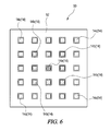
- FIG. 6 is a top view of an illumination device in accordance with a fourth embodiment of the present invention.
- FIG. 7 is a top view of an illumination device in accordance with a fifth embodiment of the present invention.
- FIG. 8 is a top view of an illumination device in accordance with a sixth embodiment of the present invention.
- an illumination device 10 is provided with a substrate 12 formed into a disc-like shape and a plurality of light-emitting devices 14 mounted on the substrate 12 .
- the substrate 12 as shown is a component on which the plurality of light-emitting devices 14 are mounted concentrically at predetermined intervals. More specifically, the substrate 12 has a disk-like shape with a center position (center) 12 a , a middle position 12 b outside of the center position 12 a , and an outer circumferential position (outer circumference) 12 c outside of the middle position 12 b , on which the plurality of light-emitting devices 14 are mounted.
- the plurality of light-emitting devices 14 are provided with: one center light-emitting device (light-emitting device) 14 a mounted at the center position 12 a of the substrate 12 ; a plurality of middle light-emitting devices (light-emitting devices) 14 b mounted at the middle position 12 b outside of the center light-emitting device 14 a at predetermined intervals; and a plurality of outer light-emitting devices (light-emitting devices) 14 c mounted at the outer circumferential position 12 c outside of the middle light-emitting devices 14 b at predetermined intervals.
- the center light-emitting device 14 a , the middle light-emitting devices 14 b , and the outer light-emitting devices 14 c each include an LED (light-emitting element) 16 that emits blue light in a wavelength range of approximately 380 to 480 nm; and an enclosure 18 that seals the LED 16 .
- LED light-emitting element
- the enclosure 18 may be formed of resin (for example, silicon or epoxy, or the like) and further include a phosphor about the LED 16 .
- the phosphor is excited by the blue light (in a wavelength range of approximately 380 to 480 nm) emitted from the LED 16 and converts the blue light into light in a wavelength range of approximately 480 to 780 nm.
- Such a phosphor may be of a white type including a yellow color.
- a combination ratio of this phosphor may be adjusted to vary the plurality of light-emitting devices 14 in a color temperature.
- a portion of the blue light emitted from the LED 16 excites a light-emitter and is converted into light within a wavelength range of approximately 480 to 780 nm, and the rest of the blue light remains unconverted and is transmitted through the resin case 18 .
- the plurality of light-emitting devices 14 may have different tints depending on an irradiation direction.
- emitted light 15 turns into bluish-white light 15 a in the vicinity of a center 22 a of an irradiation surface 22 and turns into more yellowish light 15 b with a distance from the center 22 a .
- the plurality of light-emitting devices 14 each appear to have a yellow ring generated at the outer circumference of the light-emitting devices 14 (or of the resin case 18 ).
- the plurality of light-emitting devices 14 each have a high color temperature associated with the vicinity of the center 22 a of the irradiation surface 22 and have a lower color temperature associated with a distance from the center 22 a.
- the light-emitting devices 14 as shown in FIG. 2 are arranged with the color temperature varied (more specifically, increased) in a phased manner from the center of the substrate 12 toward the outer circumference thereof (and with a corresponding distance from the center thereof) by adjusting a combination ratio of the light-emitter included in the resin case 18 .
- the color temperature of the middle light emitting devices 14 b of the plurality of light emitting devices 14 is set higher than the color temperature of the center light emitting device 14 a of the plurality of light emitting devices 14 and the color temperature of the outer light emitting devices 14 c of the plurality of light emitting devices 14 is set higher than the color temperature of the middle light emitting devices 14 b.
- a color temperature at an outer circumferential portion 24 b can be brought closer to a color temperature at a more central portion 24 a . Bringing the color temperature at the outer circumferential portion 24 b of the irradiation surface 24 of the illumination device 10 closer to the color temperature at the center portion 24 a thereof in this manner can reduce an appearance of color unevenness on the irradiation surface 24 .
- bringing the color temperature at the outer circumferential portion 24 b of the irradiation surface 24 closer to the color temperature at a center portion thereof to reduce the color unevenness may eliminate a need for subjecting light emitted from the plurality of light emitting devices 14 to diffusion processing with a reflection plate or a lens. In this case, a decrease in light extraction efficiency may be avoided.
- Additional embodiments may further be described with reference to FIGS. 4 to 8 . Similar features for the additional embodiments may be shown and provided with the same numerals as shown in FIG. 1 , and thus they are omitted from the description.
- an alternative embodiment of an illumination device 30 has a reflection plate 32 provided in what otherwise is equivalent to the illumination device 10 as shown in FIG. 1 .
- the reflection plate 32 has a reflection surface 32 a which is provided on a surface facing a plurality of light emitting devices 14 and which performs a light distribution control of light emitted from the plurality of light emitting devices 14 .
- light emitted from the plurality of light emitting devices 14 can be subjected to the light distribution control in a desired direction with the reflection surface 32 a , thus providing high illumination intensity, which facilitates achieving a higher output.
- varying the plurality of light emitting devices 14 in a color temperature can reduce an appearance of color unevenness on an irradiation surface 22 and also can avoid a decrease in light extraction efficiency.
- an illumination device 40 is provided with a substrate 42 formed into a rectangular shape, and a plurality of light emitting devices 14 mounted on the substrate 42 .
- the illumination device 40 is arranged with a color temperature varied (more specifically, increased) in a phased manner from a center of the substrate 42 toward an outer edge thereof (with distance from the center thereof) by adjusting a combination ratio of a light-emitter included in the resin case 18 of the plurality of light emitting devices 14 . More specifically, the color temperature of outer light-emitting devices 14 e of the plurality of light emitting devices 14 is set higher than a color temperature of center light-emitting devices 14 d of the plurality of light emitting devices 14 .
- an illumination device 50 is provided with a substrate 52 formed into a square shape and a plurality of light emitting devices 14 mounted on the substrate 52 .
- the illumination device 50 is arranged with a color temperature varied (more specifically, increased) in a phased manner from a center of the substrate 52 toward an outer edge thereof (with a corresponding distance from the center thereof) by adjusting a combination ratio of a light-emitter included in the resin case 18 of the plurality of light emitting devices 14 .
- a color temperature of middle light-emitting devices 14 b of the plurality of light emitting devices 14 is set higher than the color temperature of the center light-emitting device 14 a of the plurality of light emitting devices 14
- a color temperature of outer light-emitting devices 14 c of the plurality of light emitting devices 14 is set higher than the color temperature of the middle light-emitting devices 14 b .
- an illumination device 60 is provided with a substrate 62 formed into a rectangular shape and a plurality of light emitting devices 14 mounted on the substrate 62 .
- the plurality of light emitting devices 14 are provided by providing in a continuous manner one or more light-emitting units 64 each having a plurality of outer light-emitting devices 14 e with a high color temperature so arranged as to surround a center light-emitting device 14 d.
- the adjacent light-emitting units 64 share the outer light-emitting device 14 e with the high color temperature. Since the light-emitting unit 64 has the plurality of outer light-emitting devices 14 e with the high color temperature arranged around the center light-emitting device 14 d , an appearance of color unevenness at the light-emitting unit 64 can be avoided.
- Providing light-emitting units 64 in a continuous manner can reduce an appearance of color unevenness on an irradiation surface, and can avoid a decrease in light extraction efficiency.
- providing the light-emitting units 64 in a continuous manner permits the illumination device 60 to be formed into any shape such as a rectangle, thus facilitating a broader scope of potential applications for the illumination device 60 .
- an illumination device 70 is provided with a substrate 72 formed into a rectangular shape and a plurality of light emitting devices 14 mounted on the substrate 72 .
- the plurality of light emitting devices 14 are provided by plurally providing in a continuous manner a light-emitting unit 74 having a plurality of outer light-emitting devices 14 e with the high color temperature so arranged as to surround a center light-emitting device 14 d . Since the light-emitting unit 74 has the plurality of outer light-emitting devices 14 e with the high color temperature arranged around the center light-emitting device 14 d , an appearance of color unevenness at the light-emitting unit 74 can be avoided.
- this light-emitting unit 74 in a continuous manner can reduce an appearance of color unevenness on an irradiation surface, and can avoid a decrease in light extraction efficiency.
- plurally providing the light-emitting unit 74 in a continuous manner permits the illumination device 70 to be formed into any shape such as a rectangle, thus widening its use.
- the illumination devices of the present invention are not limited to the embodiments described above, and thus can be modified or improved when appropriate.
- the LED 16 that emits blue light is illustrated as a light-emitter, but an LED of a different type can also be used.
- the phosphor is of a white type including a yellow color, although it is not limited thereto.
- the color temperature is increased in a phased manner, although it is not limited thereto.
- the shapes of the substrates 12 , 42 , 52 , 62 , and 72 , the light emitting devices 14 , the LED (light-emitter) 16 , the resin case 18 , etc. are not limited to those illustrated, and thus can be modified when appropriate.
Landscapes
- Engineering & Computer Science (AREA)
- Physics & Mathematics (AREA)
- Microelectronics & Electronic Packaging (AREA)
- Optics & Photonics (AREA)
- General Engineering & Computer Science (AREA)
- Non-Portable Lighting Devices Or Systems Thereof (AREA)
- Fastening Of Light Sources Or Lamp Holders (AREA)
- Led Device Packages (AREA)
Abstract
Description
Claims (6)
Applications Claiming Priority (2)
| Application Number | Priority Date | Filing Date | Title |
|---|---|---|---|
| JP2009-003768 | 2009-01-09 | ||
| JP2009003768A JP5269623B2 (en) | 2009-01-09 | 2009-01-09 | Lighting device |
Publications (2)
| Publication Number | Publication Date |
|---|---|
| US20100200872A1 US20100200872A1 (en) | 2010-08-12 |
| US9746136B2 true US9746136B2 (en) | 2017-08-29 |
Family
ID=42539689
Family Applications (1)
| Application Number | Title | Priority Date | Filing Date |
|---|---|---|---|
| US12/685,069 Active 2034-03-23 US9746136B2 (en) | 2009-01-09 | 2010-01-11 | Illumination device having multiple LED elements with varying color temperatures |
Country Status (2)
| Country | Link |
|---|---|
| US (1) | US9746136B2 (en) |
| JP (1) | JP5269623B2 (en) |
Families Citing this family (13)
| Publication number | Priority date | Publication date | Assignee | Title |
|---|---|---|---|---|
| TWI384654B (en) * | 2009-07-31 | 2013-02-01 | 國立臺灣科技大學 | White light emitting device with adjustable color temperature |
| US10147850B1 (en) * | 2010-02-03 | 2018-12-04 | Soraa, Inc. | System and method for providing color light sources in proximity to predetermined wavelength conversion structures |
| US8905588B2 (en) * | 2010-02-03 | 2014-12-09 | Sorra, Inc. | System and method for providing color light sources in proximity to predetermined wavelength conversion structures |
| EP2458260A1 (en) * | 2010-11-24 | 2012-05-30 | Belux IP AG | LED module for lighting purposes |
| JP2012174939A (en) * | 2011-02-22 | 2012-09-10 | Panasonic Corp | Light-emitting device |
| CN102679189B (en) * | 2011-03-17 | 2014-07-23 | 海洋王照明科技股份有限公司 | Light source installation structure and light emitting diode (LED) lamp |
| CN102620169B (en) * | 2012-03-15 | 2014-04-16 | 南通大学 | Method for Selective Distribution of Color Temperature in Illuminated Areas |
| CN103712110B (en) * | 2012-03-15 | 2015-06-17 | 南通大学 | Method for selectively distributing color temperature in illuminated area of LED lamp |
| JP2014036107A (en) * | 2012-08-08 | 2014-02-24 | Toshiba Lighting & Technology Corp | Light-emitting module and luminaire |
| CN104141895A (en) * | 2013-05-10 | 2014-11-12 | 海洋王(东莞)照明科技有限公司 | LED arrangement optical system |
| CN103791286B (en) * | 2014-02-21 | 2017-03-29 | 中山星耀照明有限公司 | Linear LED light source and linear LED lamp |
| WO2018142732A1 (en) | 2017-01-31 | 2018-08-09 | Necライティング株式会社 | Led module for flashlight lamps and flashlight lamp |
| JP7245103B2 (en) * | 2019-04-05 | 2023-03-23 | スタンレー電気株式会社 | vehicle lamp |
Citations (4)
| Publication number | Priority date | Publication date | Assignee | Title |
|---|---|---|---|---|
| JP2006156192A (en) | 2004-11-30 | 2006-06-15 | Mirai:Kk | LIGHTING UNIT AND LIGHTING DEVICE HAVING THE SAME |
| JP2008218485A (en) * | 2007-02-28 | 2008-09-18 | Toshiba Lighting & Technology Corp | Light emitting device |
| US20090002604A1 (en) * | 2007-05-14 | 2009-01-01 | Sharp Kabushiki Kaisha | Light emitting apparatus, lighting device and liquid crystal display apparatus |
| US20090001392A1 (en) * | 2007-06-26 | 2009-01-01 | Lee Kwang Cheol | Light emitting device |
Family Cites Families (2)
| Publication number | Priority date | Publication date | Assignee | Title |
|---|---|---|---|---|
| WO2007063799A1 (en) * | 2005-11-30 | 2007-06-07 | Sharp Kabushiki Kaisha | Backlight device and liquid crystal display device |
| JP5029203B2 (en) * | 2006-08-11 | 2012-09-19 | 三菱化学株式会社 | Lighting device |
-
2009
- 2009-01-09 JP JP2009003768A patent/JP5269623B2/en active Active
-
2010
- 2010-01-11 US US12/685,069 patent/US9746136B2/en active Active
Patent Citations (4)
| Publication number | Priority date | Publication date | Assignee | Title |
|---|---|---|---|---|
| JP2006156192A (en) | 2004-11-30 | 2006-06-15 | Mirai:Kk | LIGHTING UNIT AND LIGHTING DEVICE HAVING THE SAME |
| JP2008218485A (en) * | 2007-02-28 | 2008-09-18 | Toshiba Lighting & Technology Corp | Light emitting device |
| US20090002604A1 (en) * | 2007-05-14 | 2009-01-01 | Sharp Kabushiki Kaisha | Light emitting apparatus, lighting device and liquid crystal display apparatus |
| US20090001392A1 (en) * | 2007-06-26 | 2009-01-01 | Lee Kwang Cheol | Light emitting device |
Also Published As
| Publication number | Publication date |
|---|---|
| US20100200872A1 (en) | 2010-08-12 |
| JP2010161021A (en) | 2010-07-22 |
| JP5269623B2 (en) | 2013-08-21 |
Similar Documents
| Publication | Publication Date | Title |
|---|---|---|
| US9746136B2 (en) | Illumination device having multiple LED elements with varying color temperatures | |
| JP5676599B2 (en) | LED package having scattering particle region | |
| US9099333B2 (en) | LED lamp device having a fluorescent element shaped for uniform light conversion | |
| US20180206411A1 (en) | Led flip chip plant grow light | |
| US9698317B2 (en) | Light emitting device having UV light emitting diode for generating human-friendly light and lighting apparatus including the same | |
| US10508778B2 (en) | Light-emitting device | |
| US9890930B2 (en) | Light source module | |
| US8502240B2 (en) | Light-emitting device package and method of manufacturing the same | |
| US10529901B2 (en) | Light emitting diode package and method for fabricating the same | |
| TW200947665A (en) | High color rendering light-emitting diodes | |
| JP2007080880A (en) | Light emitting device | |
| TWI515928B (en) | Radiation emitting component | |
| US10274164B2 (en) | Lighting device comprising a plurality of different light sources with similar off-state appearance | |
| US10177280B2 (en) | Light emitting diode | |
| US20150036342A1 (en) | Light emitting diode lamp | |
| CN103165590B (en) | Light-emitting diode and direct-light-type backlight | |
| US9080744B2 (en) | Light system with increased efficiency | |
| KR20130074762A (en) | Light-emitting device | |
| KR101518459B1 (en) | Light emitting diode package | |
| KR102029533B1 (en) | Micro Light Emitting Diodes And Their Application For Full Color Display Device | |
| TW201320411A (en) | Optoelectronic semiconductor component and module having a plurality of such components | |
| TW201304207A (en) | Illumination device | |
| KR20210100057A (en) | Light emitting device | |
| JP7072368B2 (en) | Side-illuminated LED light emitting device | |
| US20140217430A1 (en) | Optoelectronic semiconductor unit and module comprising a plurality of such units |
Legal Events
| Date | Code | Title | Description |
|---|---|---|---|
| AS | Assignment |
Owner name: PANASONIC ELECTRIC WORKS CO., LTD., JAPAN Free format text: ASSIGNMENT OF ASSIGNORS INTEREST;ASSIGNOR:TAKASHIMA, JUN;REEL/FRAME:024313/0750 Effective date: 20100407 |
|
| AS | Assignment |
Owner name: PANASONIC CORPORATION, JAPAN Free format text: MERGER;ASSIGNOR:PANASONIC ELECTRIC WORKS CO.,LTD.,;REEL/FRAME:027697/0525 Effective date: 20120101 |
|
| AS | Assignment |
Owner name: PANASONIC INTELLECTUAL PROPERTY MANAGEMENT CO., LTD., JAPAN Free format text: ASSIGNMENT OF ASSIGNORS INTEREST;ASSIGNOR:PANASONIC CORPORATION;REEL/FRAME:034194/0143 Effective date: 20141110 Owner name: PANASONIC INTELLECTUAL PROPERTY MANAGEMENT CO., LT Free format text: ASSIGNMENT OF ASSIGNORS INTEREST;ASSIGNOR:PANASONIC CORPORATION;REEL/FRAME:034194/0143 Effective date: 20141110 |
|
| STCF | Information on status: patent grant |
Free format text: PATENTED CASE |
|
| AS | Assignment |
Owner name: PANASONIC INTELLECTUAL PROPERTY MANAGEMENT CO., LTD., JAPAN Free format text: CORRECTIVE ASSIGNMENT TO CORRECT THE ERRONEOUSLY FILED APPLICATION NUMBERS 13/384239, 13/498734, 14/116681 AND 14/301144 PREVIOUSLY RECORDED ON REEL 034194 FRAME 0143. ASSIGNOR(S) HEREBY CONFIRMS THE ASSIGNMENT;ASSIGNOR:PANASONIC CORPORATION;REEL/FRAME:056788/0362 Effective date: 20141110 |
|
| MAFP | Maintenance fee payment |
Free format text: PAYMENT OF MAINTENANCE FEE, 4TH YEAR, LARGE ENTITY (ORIGINAL EVENT CODE: M1551); ENTITY STATUS OF PATENT OWNER: LARGE ENTITY Year of fee payment: 4 |
|
| MAFP | Maintenance fee payment |
Free format text: PAYMENT OF MAINTENANCE FEE, 8TH YEAR, LARGE ENTITY (ORIGINAL EVENT CODE: M1552); ENTITY STATUS OF PATENT OWNER: LARGE ENTITY Year of fee payment: 8 |