US9744836B1 - Telescoping truck bed shell - Google Patents
Telescoping truck bed shell Download PDFInfo
- Publication number
- US9744836B1 US9744836B1 US15/478,138 US201715478138A US9744836B1 US 9744836 B1 US9744836 B1 US 9744836B1 US 201715478138 A US201715478138 A US 201715478138A US 9744836 B1 US9744836 B1 US 9744836B1
- Authority
- US
- United States
- Prior art keywords
- frames
- cover
- truck
- stored position
- shell
- Prior art date
- Legal status (The legal status is an assumption and is not a legal conclusion. Google has not performed a legal analysis and makes no representation as to the accuracy of the status listed.)
- Active
Links
- 230000004888 barrier function Effects 0.000 claims description 4
- 239000000463 material Substances 0.000 description 9
- 230000007246 mechanism Effects 0.000 description 5
- XLYOFNOQVPJJNP-UHFFFAOYSA-N water Substances O XLYOFNOQVPJJNP-UHFFFAOYSA-N 0.000 description 2
- 229920000049 Carbon (fiber) Polymers 0.000 description 1
- XAGFODPZIPBFFR-UHFFFAOYSA-N aluminium Chemical compound [Al] XAGFODPZIPBFFR-UHFFFAOYSA-N 0.000 description 1
- 229910052782 aluminium Inorganic materials 0.000 description 1
- 239000004917 carbon fiber Substances 0.000 description 1
- 238000004891 communication Methods 0.000 description 1
- 230000007812 deficiency Effects 0.000 description 1
- 230000003292 diminished effect Effects 0.000 description 1
- 239000011152 fibreglass Substances 0.000 description 1
- VNWKTOKETHGBQD-UHFFFAOYSA-N methane Chemical compound C VNWKTOKETHGBQD-UHFFFAOYSA-N 0.000 description 1
- 230000002093 peripheral effect Effects 0.000 description 1
- 230000001681 protective effect Effects 0.000 description 1
- 238000007789 sealing Methods 0.000 description 1
- 239000007787 solid Substances 0.000 description 1
Images


Classifications
-
- B—PERFORMING OPERATIONS; TRANSPORTING
- B60—VEHICLES IN GENERAL
- B60J—WINDOWS, WINDSCREENS, NON-FIXED ROOFS, DOORS, OR SIMILAR DEVICES FOR VEHICLES; REMOVABLE EXTERNAL PROTECTIVE COVERINGS SPECIALLY ADAPTED FOR VEHICLES
- B60J7/00—Non-fixed roofs; Roofs with movable panels, e.g. rotary sunroofs
- B60J7/08—Non-fixed roofs; Roofs with movable panels, e.g. rotary sunroofs of non-sliding type, i.e. movable or removable roofs or panels, e.g. let-down tops or roofs capable of being easily detached or of assuming a collapsed or inoperative position
- B60J7/12—Non-fixed roofs; Roofs with movable panels, e.g. rotary sunroofs of non-sliding type, i.e. movable or removable roofs or panels, e.g. let-down tops or roofs capable of being easily detached or of assuming a collapsed or inoperative position foldable; Tensioning mechanisms therefor, e.g. struts
- B60J7/14—Non-fixed roofs; Roofs with movable panels, e.g. rotary sunroofs of non-sliding type, i.e. movable or removable roofs or panels, e.g. let-down tops or roofs capable of being easily detached or of assuming a collapsed or inoperative position foldable; Tensioning mechanisms therefor, e.g. struts with a plurality of rigid plate-like elements or rigid non plate-like elements, e.g. with non-slidable, but pivotable or foldable movement
- B60J7/141—Non-fixed roofs; Roofs with movable panels, e.g. rotary sunroofs of non-sliding type, i.e. movable or removable roofs or panels, e.g. let-down tops or roofs capable of being easily detached or of assuming a collapsed or inoperative position foldable; Tensioning mechanisms therefor, e.g. struts with a plurality of rigid plate-like elements or rigid non plate-like elements, e.g. with non-slidable, but pivotable or foldable movement for covering load areas, e.g. for pick-up trucks
-
- B—PERFORMING OPERATIONS; TRANSPORTING
- B60—VEHICLES IN GENERAL
- B60J—WINDOWS, WINDSCREENS, NON-FIXED ROOFS, DOORS, OR SIMILAR DEVICES FOR VEHICLES; REMOVABLE EXTERNAL PROTECTIVE COVERINGS SPECIALLY ADAPTED FOR VEHICLES
- B60J7/00—Non-fixed roofs; Roofs with movable panels, e.g. rotary sunroofs
- B60J7/02—Non-fixed roofs; Roofs with movable panels, e.g. rotary sunroofs of sliding type, e.g. comprising guide shoes
- B60J7/04—Non-fixed roofs; Roofs with movable panels, e.g. rotary sunroofs of sliding type, e.g. comprising guide shoes with rigid plate-like element or elements, e.g. open roofs with harmonica-type folding rigid panels
- B60J7/041—Non-fixed roofs; Roofs with movable panels, e.g. rotary sunroofs of sliding type, e.g. comprising guide shoes with rigid plate-like element or elements, e.g. open roofs with harmonica-type folding rigid panels for utility vehicles, e.g. with slidable and foldable rigid panels
-
- B—PERFORMING OPERATIONS; TRANSPORTING
- B60—VEHICLES IN GENERAL
- B60J—WINDOWS, WINDSCREENS, NON-FIXED ROOFS, DOORS, OR SIMILAR DEVICES FOR VEHICLES; REMOVABLE EXTERNAL PROTECTIVE COVERINGS SPECIALLY ADAPTED FOR VEHICLES
- B60J7/00—Non-fixed roofs; Roofs with movable panels, e.g. rotary sunroofs
- B60J7/08—Non-fixed roofs; Roofs with movable panels, e.g. rotary sunroofs of non-sliding type, i.e. movable or removable roofs or panels, e.g. let-down tops or roofs capable of being easily detached or of assuming a collapsed or inoperative position
-
- B—PERFORMING OPERATIONS; TRANSPORTING
- B60—VEHICLES IN GENERAL
- B60P—VEHICLES ADAPTED FOR LOAD TRANSPORTATION OR TO TRANSPORT, TO CARRY, OR TO COMPRISE SPECIAL LOADS OR OBJECTS
- B60P3/00—Vehicles adapted to transport, to carry or to comprise special loads or objects
- B60P3/42—Vehicles adapted to transport, to carry or to comprise special loads or objects convertible from one use to a different one
-
- B—PERFORMING OPERATIONS; TRANSPORTING
- B62—LAND VEHICLES FOR TRAVELLING OTHERWISE THAN ON RAILS
- B62D—MOTOR VEHICLES; TRAILERS
- B62D33/00—Superstructures for load-carrying vehicles
- B62D33/04—Enclosed load compartments ; Frameworks for movable panels, tarpaulins or side curtains
-
- B—PERFORMING OPERATIONS; TRANSPORTING
- B62—LAND VEHICLES FOR TRAVELLING OTHERWISE THAN ON RAILS
- B62D—MOTOR VEHICLES; TRAILERS
- B62D33/00—Superstructures for load-carrying vehicles
- B62D33/08—Superstructures for load-carrying vehicles comprising adjustable means
Definitions
- Trucks are one of the most popular types of vehicles being sold in the United States and abroad. Users will accessorize the truck with a variety of functional components in order to fit their lifestyle and needs. However, in doing so, they may add certain functionality but also disable other functional aspects of the truck.
- a truck bed shell is disclosed herein which has two different configurations.
- a collapsed configuration wherein the user may have full access to the truck bed and a deployed configuration wherein the user may have a protective covering over the truck bed in order to provide for an enclosed protected volume to store things.
- the truck bed shell may have a plurality of frames that are traversable between retracted and extended positions that provide protection to sides of the truck bed when the frames are in the extended position.
- the truck bed shell may also have a cover that is traversable between retracted and extended positions that provide protection to a top side of the truck bed when the cover is in the extended position.
- a truck with a collapsible shell may comprise the truck in the collapsible shell.
- the truck may have a cab defining a roof and a truck bed defining first and second sidewalls and a tailgate.
- the collapsible shell may have a plurality of first frames and a plurality of second frames and the cover.
- the plurality of first frames may be stackable adjacent to each other.
- the plurality of first frames may be mounted to the first sidewall.
- the plurality of first frames may be traversable between a stored position wherein the plurality of first frames are stackable adjacent to each other and an extended position wherein the plurality of second frames are disposed end to end with each other.
- the plurality of second frames may be stackable adjacent to each other.
- the plurality of second frames may be mounted to the second sidewall.
- the plurality of second frames may be traversable between a stored position wherein the plurality of second frames are stackable adjacent to each other and an extended position wherein the plurality of second frames are disposed end to end with each other.
- the cover may be traversable between a stored position and an extended position wherein in the stored position, the cover is disposed above the roof of the cab and in the extended position, the cover is engaged to the plurality of first and second frames to form an enclosed space at the bed of the truck.
- the cover When the cover is in the stored position and the plurality of first and second frames are in the stored position, a full length of the truck bed is usable.
- the cover When the cover is in the extended position and the plurality of first and second frames are in the extended position, the shell forms a covered interior volume over the truck bed.
- the truck may further comprise a plurality of panels. Each of the panels may be attachable to the first and second frame to provide a barrier.
- the truck may further comprise first and second tracks mounted to the first and second sidewalls and a plurality of first and second sliders mounted to the plurality of first and second frames.
- the plurality of first and second sliders may be slidably engaged to the first and second tracks.
- the truck may further comprise a shield disposed over the cover when the cover is in the stored position over the roof of the cab.
- the shield may be traversable between an open position and a use position wherein in the open position, the cover is traversable from the stored position to the extended position and in the stored position, the cover provides an aerodynamic shield for the cover when the cover is in the stored position.
- the shield may be rotatably attached to the roof of the cab.
- the plurality of first and second frames may be panels.
- a collapsible shell may be attachable to a truck.
- the collapsible shell may comprise a plurality of first frames, a plurality of second frames and the cover.
- the plurality of first frames may be stackable adjacent to each other.
- the plurality of first frames may be mountable to a first sidewall of a bed of the truck.
- the plurality of first frames may be traversable between a stored position wherein the plurality of first frames are stackable adjacent to each other and an extended position wherein the plurality of second frames are disposed end to end with each other.
- the plurality of second frames may be stackable adjacent to each other.
- the plurality of second frames may be mountable to a second sidewall of the bed of the truck.
- the plurality of second frames may be traversable between a stored position wherein the plurality of second frames are stackable adjacent to each other and an extended position wherein the plurality of second frames are disposed end to end with each other.
- the cover may be traversable between a stored position and an extended position wherein in the stored position and during use, the cover is disposed above a roof of the cab and in the extended position.
- the cover may be engagable to the plurality of first and second frames to form an enclosed space at the bed of the truck.
- the cover When the cover is in the stored position and the plurality of first and second frames are in the stored position during use, a full length of the truck bed is accessible, and when the cover is in the extended position and the plurality of first and second frames are in the extended position during use, the shell forms a covered interior volume over the truck bed.
- the collapsible shell may further comprising a plurality of panels. Each panel may be attachable to the first and second frame to provide a barrier.
- the collapsible shell may comprise first and second tracks mountable to the first and second sidewalls and a plurality of first and second sliders mounted to the plurality of first and second frames.
- the plurality of first and second sliders may be slidably engaged to the first and second tracks during use.
- the collapsible shell may further comprise a shield attachable to the cab and disposable over the cover when the cover is in the stored position over the roof of the cab during use.
- the shield may be traversable between an open position and a use position during use wherein in the open position during use.
- the cover may be traversable from the stored position to the extended position and in the stored position during use, the cover provides an aerodynamic shield for the cover when the cover is in the stored position.
- the shield may be rotatably attached to the roof of the cab during use of the collapsible shell.
- the plurality of first and second frames may be panels.
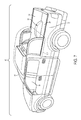
- FIG. 1 is a perspective view of a truck and a first embodiment of a telescoping truck bed shell
- FIG. 2 illustrates the telescoping truck bed shell shown in FIG. 1 as frames are being deployed
- FIG. 3 illustrates the telescoping truck bed shell shown in FIG. 1 when the frames are fully deployed
- FIG. 4 illustrates a shield rotated upward to prepare for deployment of a cover of the telescoping truck bed shell
- FIG. 5 illustrates the shield rotated back downward and the cover being deployed
- FIG. 6 illustrates the cover when fully deployed
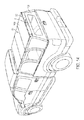
- FIG. 7 is a perspective view of the truck and the second embodiment of the telescoping truck bed shell
- FIG. 8 illustrates the shield rotated upward to access crossmembers attachable to frames of the telescoping truck bed shell shown in FIG. 7 ;
- FIG. 9 illustrates the shield rotated fully upward
- FIG. 10 illustrates the crossmember attached to the frame of the telescoping truck bed shell shown in FIG. 7 ;
- FIG. 11 illustrates deployment of the frames of the telescoping truck bed shell shown in FIG. 7 ;
- FIG. 12 illustrates full deployment of the frames and the cross members attached to the frames
- FIG. 13 illustrates the cover being deployed over the frames
- FIG. 14 illustrates the cover when fully deployed and the shield when rotated back downward.
- a truck 10 having a collapsible shell 12 , 112 is shown.
- the collapsible shell 12 , 112 may be traversed to a stored position, as shown in FIGS. 1 and 7 which allows the user to have full access a bed 14 of the truck.
- the collapsible shell 12 , 112 may also be traversed to an extended position, as shown in FIGS. 6 and 14 which provides for a protected interior volume under a cover 16 , 116 at the truck bed 14 .
- the collapsible shell 12 , 112 provides for either full access to the truck bed when the collapsible shell 12 , 112 is in the collapsed or stored position or when needed an interior protected volume at the truck bed 14 so that utility of the truck bed 14 is not diminished when the collapsible shell 12 , 112 is mounted to the truck 10 .
- the user can load a full-sized motorcycle on top of the truck bed 14 when the collapsible shell 12 , 112 is in the collapsed or stored position.
- the user can also traverse the collapsible shell 12 , 112 to the extended or erected position when needed in order to create the interior protected volume at the truck bed 14 to store things.
- the collapsible shell 12 , 112 is discussed herein in relation to the truck 10 having the truck bed 14 . However, it is also contemplated that the collapsible shell 12 , 112 may also be mounted to any type of vehicle having a cargo area with an open top area. By way of example and not limitation, the collapsible shell 12 , 112 may also be mounted to a golf cart having an open cargo area or container behind the passenger area. Additionally, the collapsible shell 12 , 112 may be mounted to a container having an open top.
- the truck 10 may define a cab 18 having a roof 20 .
- the truck bed 14 may define first and second sidewalls 22 , 24 which are positioned on opposite sides of a floor 26 of the truck bed 14 .
- the collapsible shell 12 , 112 may be mounted to other types of vehicle as well as to a container. In this regard, opposed walls of the container would be the functional equivalent of the first and second sidewalls 22 , 24 of the truck bed 14 .
- the second embodiment of the collapsible shell 112 shown in FIGS. 7-14 is identical to the first embodiment of the collapsible shell 12 shown in FIGS. 1-6 except as described further below.
- the collapsible shell 12 may have a plurality of first frames 28 a - n and a plurality of second frames 30 a - n .
- the first and second frames 28 a - c , 30 a - c may be slidably mounted to the first and second sidewalls 22 , 24 of the truck bed 14 .
- the plurality of first frames may be slidably mounted to the first sidewall 22 by installing a sliding track 32 on an upper edge or surface of the first sidewall 22 .
- the plurality of second frames may be slidably mounted to the second sidewall 24 by installing a sliding track 34 on an upper edge or surface of the second sidewall 24 .
- Followers may be mounted to a bottom side of the frames 28 , 30 wherein the followers slidably engaged the first and second sliding tracks 32 , 34 .
- the followers and sliding tracks 32 , 34 allow the first and second frames 28 , 30 to slide between a collapsed position and an extended position.
- FIG. 3 illustrates the plurality of first and second frames 28 , 30 when the frames 28 , 30 are in the fully extended position.
- the first frames 28 b , 28 c may be slidably mounted to the first sidewall 22 while the first frame 28 a may be rigidly secured to the first sidewall 22 or sliding track 32 .
- the second frames 30 b , 30 c may be slidably mounted to the second sidewall 24 while the second frame 30 a may be rigidly secured to the second sidewall 24 or sliding track 34 .
- Front portions 36 , 38 of the frames 28 a , 30 a may be attached to the cab 18 in a manner that allows for some flex. As the truck 10 moves over uneven terrain, the cab 18 may move independent from the truck bed 14 .
- the sliding track 32 , 34 may each have two races.
- the first race of the sliding track 32 may receive the follower attached to the first frame 28 b .
- the second race of the sliding track 32 may receive the follower attached to the first frame 28 c .
- the first race of the sliding track 34 may receive the follower attached to the second frame 30 b .
- the second race of the sliding track 34 may receive the follower attached to the second frame 30 c .
- the frames 28 a and 30 a may be fixedly secured to the first and second sidewall 22 , 24 .
- the follower may be a tongue and the first and second races of the first sliding track 32 may be grooves that receive the follower.
- the follower and the first and second races may have a ball bearing engagement between the two so that the weight of the frames 28 b, c , 30 b, c does not hinder sliding movement of the frames 28 b, c , 30 b, c along the first and second sliding tracks 32 , 34 .
- the first and second frames 28 a , 30 a may be slidably attached to the first and second sidewalls 22 , 24 by providing for an additional race in the first and second sliding tracks 32 , 34 that receive followers that are attached to the first and second frames 28 a , 30 a .
- the followers may be secured to the bottom side of the frames 28 , 30 .
- the races may be parallel to each other.
- first frames 28 b , 28 c may be slidably attached to the first frames 28 a , 28 b .
- second frames 30 b, c may be slidably attached to the second frames 30 a, b .
- the slidable attachment between the respective first and second frames 28 a, b, c and 30 a, b, c may be achieved through a tongue and groove connection between the first frames 28 b to 28 a and 28 c to 28 b as well as between the second frames 30 b to 30 a and 30 c to 30 b .
- the first and second frames 28 , 30 When the first and second frames 28 , 30 are in the extended position, as shown in FIG. 3 , the first and second frames 28 , 30 may be locked to the extended position.
- the frames 28 , 30 may each be fabricated from a rigid tubular material.
- the rigid tubular material has an L-shape.
- the rigid tubular material may be rectangularly shaped.
- the L-shaped tubular material may also have a generally rigid panel 31 which may be opaque, transparent or translucent.
- the followers may be attached to the bottom sides of the rigid panel for mounting to the sliding tracks 32 , 34 . If the frames 28 , 30 are rectangularly shaped tubular material, then the followers may be attached to the bottom sides of the rigid tubular material of the bottom side thereof.
- the frame 28 , 30 may also be utilized including but not limited to fiberglass, carbon fiber, aluminum or solid bar.
- the frame 28 , 30 may be fabricated from a material that can withstand wind and driving forces due to the truck 10 driving on the freeway at speeds of up to 65-90 mph and cornering.
- the frames 28 , 30 may collapse and extend along the sidewalls 22 , 24 of the truck bed 14 .
- the frames 28 , 30 may not provide any protection on the top of the shell 12 , 112 . Rather, the frames 28 , 30 only protect the sides of the collapsible shell 12 , 112 .
- the collapsible shell 12 , 112 may further have a cover 16 that can be secured to the frames 28 , 30 when the frames 28 , 30 are telescoped out to the extended position (see FIG. 4 ).
- the cover 16 may start from a stored position collapsed over the cab 18 of the truck 10 .
- a fairing 40 may shield the cover 16 so that as the truck 10 moves forward, oncoming wind flows over the cover 16 and the cover 16 does not add to the wind resistance of the truck 10 . Moreover, the fairing 40 mitigates the possibility that wind will pick the cover 16 up inadvertently when the cover 16 stored position and rip the cover 16 off of the roof of the cab.
- the frames 28 , 30 are shown as having an open top when the frames 28 , 30 are in the extended position it is also contemplated that the frames 28 , 30 may extended inward or medially at the top so as to provide protection to the top side of the shell 12 , 112 .
- the medial sides of the extended portions of the frames 28 , 30 may join together and provide for a watertight seal.
- the cover 16 may comprise a plurality of panels that can be stacked upon each other in an accordion fashion. This is shown in FIGS. 5 and 6 .
- Four panels 42 a - d may make up the cover 16 .
- the cover may be fabricated from one or more panels 42 . If it is only a single panel, then the panel 42 would cover only the topside of the shell 12 but not the backside of the collapsible shell 12 , 112 .
- the cover 16 is shown as being a plurality of rigid panels that are stacked in an accordion fashion.
- cover 16 may be fabricated from a flexible material that can be rolled up and disposed under the fairing 40 then unrolled in order to protect or form an enclosure over the truck bed 14 in conjunction with the frames 28 , 30 .
- the flex cover 16 would also be capable of being unrolled to cover the back side of the shell 12 .
- the cover 16 may be sufficiently wide in order to engage the topsides of the frames 28 , 30 . More particularly, the cover 16 may form a seal along the topsides of the frames 28 , 30 wherein the seal may be watertight to provide a dry interior volume over the truck bed 14 .
- the cover 16 may have a rubber seal along the outer peripheral edges that engage the frames 28 , 30 to form that watertight seal.
- the cover 16 may be secured to the frames 28 , 30 with latches including but not limited to rubber latches or mechanically operated latches.
- the fairing 40 which may be pivotally attached to the roof 20 of the cab 18 may be pivoted upward as shown in FIG. 3 .
- the fairing 40 may be held in the upward position by a spring.
- the fairing 40 may also be held in the down position or stored position with the latch to resist the upward spring motion.
- the latch may be attachable to the shield and the roof of the cab and be detachable in order to traverse the fairing 40 to the upward position.
- the fairing 40 By pivoting the fairing 40 upward, this provides room or allows the cover 16 to be unfolded over the truck bed as shown in FIGS. 5 and 6 .
- the fairing 40 may be placed back to the down position, as shown in FIGS. 5 and 6 and locked into place with a lock.
- the cover 16 may also be secured to the frames 28 , 30 with a locking mechanism 44 .
- a plurality of locking mechanism 44 may be disposed along the length of the frames 28 , 30 so as to engage the frames 28 , 30 and the cover 16 to each
- the frames 28 , 30 are shown as being stacked upon each other as shown in FIG. 1 .
- the frames 28 b, c and 30 b, c may slide outward and also pivot into alignment with the frame 28 a , 30 a so that the frames 28 a, b, c are in the same plane and the frames 30 a, b, c are in the same plane.
- the frames 28 b, c and 30 b, c are shown as being offset from the frame 28 a , 30 a in FIG. 2 . This shows the frames 28 b,c , and 30 b,c before they are pivoted into alignment with the frames 28 a , 30 a.
- the fairing 40 may also have a cutout to allow for the panels 42 which may be too wide for the fairings 40 , as shown in FIG. 1 .
- the cutout 46 allows the panels 42 to extend beyond the width of the fairing 40 .
- the collapsible shell 112 is identical to the collapsible shell 12 discussed in relation FIGS. 1-6 . However, certain differences do exist which are described below.
- the frames 28 a , 30 a may be fixedly attached to the sidewalls 22 , 24 . Additionally, a crossbar 148 may be attached to the frames 28 , 30 .
- the fairing 140 may additionally have a rear flap 150 that is flexible and pivotable about a rear edge 152 of the fairing 140 .
- the fairing 140 may optionally not have the cutout 46 because the panels 142 of the cover 116 may be modified so as to be narrower than a width of the fairing 140 .
- the panels 142 of the cover 116 is only wider than the fairing 140 because the panel 142 d extends outward at the bottom so that the panel 142 d can form an enclosure about the entire width of the upper edge 154 of the tailgate 156 of the truck 10 .
- the panel 142 d may have pivoting side flaps 158 which are folded inward as shown in FIG.
- the fairing 140 may be traversable between the upper position and the down position in the same manner as that of fairing 40 with or without a spring to traverse the fairing 40 to the upward position and with or without a latch to hold the fairing 140 in the downward position. The same is true for fairing 40 .
- the panel 142 are deployed in the same manner in relation to the panels 42 discussed in relation to FIGS. 1-6 except that in the embodiment shown in FIGS. 7-14 , there is an extra step of unfolding the side flaps 158 outward for engaging the panel 142 to the closed position, as shown in FIG. 14 .
- the collapsible shell 112 may have supporting cross members 160 that may be attached to the frames 28 b, c and 30 b, c , shown in FIG. 12 .
- the supporting cross members 160 provide additional rigidity to the collapsible shell 112 .
- the cover 116 may have a pivoting joint 162 that allows the panels 142 c and 142 d to pivot about each other.
- the pivoting joint 162 may also be secured to the supporting crossmember 160 attached to the frames 28 c , 30 c .
- the cover 16 may be secured to the frames 28 , 30 with latches including but not limited to rubber latches or mechanically operated latches.
- the supporting crossmembers 160 may be stored under the fairing 141 the collapsible shell 112 is in the collapsed position.
- the supporting crossmembers 160 may be attached to the frames 28 b, c and 30 b, c with quick attach mechanisms known in the art or developed in the future.
- the crossmembers 160 and the frames 28 , 30 may have quick detach mechanisms so that the supporting crossmembers 160 may be removably attached to the frames 28 , 30 so that the supporting crossmember 160 may be stored in the fairing 140 when the collapsible shell 112 is in the collapsed position.
- the supporting crossmember 160 may be removed from fairing 140 and attached to the frames 28 b, c and 30 b, c to attach to the frames 28 , 30 .
- the crossmembers 160 may be used to assist in deploying and storing the shell 12 , 112 .
- the collapsible shell 12 , 112 may be traversed from the stored or collapsed position to the extended position either manually or under the power of a motor. When done manually, the user will grasp the frame 28 c and begin to pull the frame 28 c toward the tailgate. Additionally, the user will grasp 30 c and begin to pull the frame 30 c toward the tailgate. By doing so, the frames 28 b, c and 30 b, c are traversed to the extended position. Alternatively, for the collapsible shell 112 , the user may secure the supporting crossmember 160 to the frame 28 c and 30 c first and then grip the supporting crossmember 160 and traverse the supporting crossmember 160 toward the tailgate.
- the frames 28 b, c and 30 b, c may be traversed to the extended position under the power of a motor.
- the motor may drive a rack and pinion configuration attached to the frames 28 b, c to either the frame 28 a or sidewall 22 .
- the same or different motor may also drive the rack and pinion configuration attached to the frames 30 b, c attached to either the frame 38 or sidewall 24 .
- the motor(s) may be actuated by a controller to either traverse the frames 28 b, c , 30 b, c to the extended position and/or back to the collapsed position.
- the fairing 40 , 140 are shown as being rotatably attached to the cab of the truck. However, the fairing 40 , 140 may also be removable from the cab of the truck so that the user can remove the shell from the truck if desired.
- truck cabs may have integrated rails on the driver side and passenger side of the cab of the truck.
- the fairing 40 , 140 may be removably attached to the left and right rails on the top of the cab.
- the fairing 40 , 140 may also be integrated into the cab of the truck in that it is not removable without significant time and effort.
- the cover 16 , 116 may have an integrated third brake light 17 , 117 .
- the third brake light 17 , 117 may be in electrical communication with the electrical system of the truck so that the third brake light 17 , 117 is illuminated when brakes of the truck are actuated.
- the third brake light 17 , 117 may be disposed between panels 42 c and 42 d for the embodiment shown in FIGS. 1-6 and between panels 142 c and 142 d for the embodiment shown in FIG. 7-14 .
- the cover 16 , 116 and the frames 28 , 30 , 128 , 130 when in the deployed state shown in FIGS. 6 and 14 may be waterproof so that rain water does not and cannot enter the truck bed area.
- the cover 16 , 116 and the frames 28 , 30 , 128 , 130 may have rubber seals and other sealing mechanisms for keep the water out of the truck bed area.
Abstract
A telescoping truck bed shell is disclosed herein. The truck bed shell is capable of being retracted so that the user can have full access to the truck bed and also extended so that the user can have a protected volume at the truck bed in order to store things. The telescoping truck bed has traversable frames and a traversable cover wherein the frames and cover may be traversed between extended and retracted positions depending on whether the truck bed shell is being deployed or stored.
Description
Not Applicable
Not Applicable
The various aspects and embodiments described herein relate to a truck bed shell.
Trucks are one of the most popular types of vehicles being sold in the United States and abroad. Users will accessorize the truck with a variety of functional components in order to fit their lifestyle and needs. However, in doing so, they may add certain functionality but also disable other functional aspects of the truck.
Accordingly, there is a need in the art for improvement in accessorizing trucks.
The various aspects and embodiments described herein address the deficiencies discussed above, discussed below and those that are known in the art.
A truck bed shell is disclosed herein which has two different configurations. A collapsed configuration wherein the user may have full access to the truck bed and a deployed configuration wherein the user may have a protective covering over the truck bed in order to provide for an enclosed protected volume to store things. The truck bed shell may have a plurality of frames that are traversable between retracted and extended positions that provide protection to sides of the truck bed when the frames are in the extended position. The truck bed shell may also have a cover that is traversable between retracted and extended positions that provide protection to a top side of the truck bed when the cover is in the extended position.
More particularly, a truck with a collapsible shell is disclosed. The may comprise the truck in the collapsible shell. The truck may have a cab defining a roof and a truck bed defining first and second sidewalls and a tailgate. The collapsible shell may have a plurality of first frames and a plurality of second frames and the cover. The plurality of first frames may be stackable adjacent to each other. The plurality of first frames may be mounted to the first sidewall. The plurality of first frames may be traversable between a stored position wherein the plurality of first frames are stackable adjacent to each other and an extended position wherein the plurality of second frames are disposed end to end with each other. The plurality of second frames may be stackable adjacent to each other. The plurality of second frames may be mounted to the second sidewall. The plurality of second frames may be traversable between a stored position wherein the plurality of second frames are stackable adjacent to each other and an extended position wherein the plurality of second frames are disposed end to end with each other. The cover may be traversable between a stored position and an extended position wherein in the stored position, the cover is disposed above the roof of the cab and in the extended position, the cover is engaged to the plurality of first and second frames to form an enclosed space at the bed of the truck.
When the cover is in the stored position and the plurality of first and second frames are in the stored position, a full length of the truck bed is usable. When the cover is in the extended position and the plurality of first and second frames are in the extended position, the shell forms a covered interior volume over the truck bed.
The truck may further comprise a plurality of panels. Each of the panels may be attachable to the first and second frame to provide a barrier.
The truck may further comprise first and second tracks mounted to the first and second sidewalls and a plurality of first and second sliders mounted to the plurality of first and second frames. The plurality of first and second sliders may be slidably engaged to the first and second tracks.
The truck may further comprise a shield disposed over the cover when the cover is in the stored position over the roof of the cab. The shield may be traversable between an open position and a use position wherein in the open position, the cover is traversable from the stored position to the extended position and in the stored position, the cover provides an aerodynamic shield for the cover when the cover is in the stored position. The shield may be rotatably attached to the roof of the cab.
The plurality of first and second frames may be panels.
In another aspect, a collapsible shell may be attachable to a truck. The collapsible shell may comprise a plurality of first frames, a plurality of second frames and the cover. The plurality of first frames may be stackable adjacent to each other. The plurality of first frames may be mountable to a first sidewall of a bed of the truck. The plurality of first frames may be traversable between a stored position wherein the plurality of first frames are stackable adjacent to each other and an extended position wherein the plurality of second frames are disposed end to end with each other. The plurality of second frames may be stackable adjacent to each other. The plurality of second frames may be mountable to a second sidewall of the bed of the truck. The plurality of second frames may be traversable between a stored position wherein the plurality of second frames are stackable adjacent to each other and an extended position wherein the plurality of second frames are disposed end to end with each other. The cover may be traversable between a stored position and an extended position wherein in the stored position and during use, the cover is disposed above a roof of the cab and in the extended position. The cover may be engagable to the plurality of first and second frames to form an enclosed space at the bed of the truck.
When the cover is in the stored position and the plurality of first and second frames are in the stored position during use, a full length of the truck bed is accessible, and when the cover is in the extended position and the plurality of first and second frames are in the extended position during use, the shell forms a covered interior volume over the truck bed.
The collapsible shell may further comprising a plurality of panels. Each panel may be attachable to the first and second frame to provide a barrier.
The collapsible shell may comprise first and second tracks mountable to the first and second sidewalls and a plurality of first and second sliders mounted to the plurality of first and second frames. The plurality of first and second sliders may be slidably engaged to the first and second tracks during use.
The collapsible shell may further comprise a shield attachable to the cab and disposable over the cover when the cover is in the stored position over the roof of the cab during use.
The shield may be traversable between an open position and a use position during use wherein in the open position during use. The cover may be traversable from the stored position to the extended position and in the stored position during use, the cover provides an aerodynamic shield for the cover when the cover is in the stored position.
The shield may be rotatably attached to the roof of the cab during use of the collapsible shell.
The plurality of first and second frames may be panels.
These and other features and advantages of the various embodiments disclosed herein will be better understood with respect to the following description and drawings, in which like numbers refer to like parts throughout, and in which:
Referring now to the drawings, a truck 10 having a collapsible shell 12, 112 is shown. The collapsible shell 12, 112 may be traversed to a stored position, as shown in FIGS. 1 and 7 which allows the user to have full access a bed 14 of the truck. The collapsible shell 12, 112 may also be traversed to an extended position, as shown in FIGS. 6 and 14 which provides for a protected interior volume under a cover 16, 116 at the truck bed 14. In this manner, the collapsible shell 12, 112 provides for either full access to the truck bed when the collapsible shell 12, 112 is in the collapsed or stored position or when needed an interior protected volume at the truck bed 14 so that utility of the truck bed 14 is not diminished when the collapsible shell 12, 112 is mounted to the truck 10. The user can load a full-sized motorcycle on top of the truck bed 14 when the collapsible shell 12, 112 is in the collapsed or stored position. When needed, the user can also traverse the collapsible shell 12, 112 to the extended or erected position when needed in order to create the interior protected volume at the truck bed 14 to store things.
The collapsible shell 12, 112 is discussed herein in relation to the truck 10 having the truck bed 14. However, it is also contemplated that the collapsible shell 12, 112 may also be mounted to any type of vehicle having a cargo area with an open top area. By way of example and not limitation, the collapsible shell 12, 112 may also be mounted to a golf cart having an open cargo area or container behind the passenger area. Additionally, the collapsible shell 12, 112 may be mounted to a container having an open top.
The truck 10 may define a cab 18 having a roof 20. The truck bed 14 may define first and second sidewalls 22, 24 which are positioned on opposite sides of a floor 26 of the truck bed 14. As discussed above, the collapsible shell 12, 112 may be mounted to other types of vehicle as well as to a container. In this regard, opposed walls of the container would be the functional equivalent of the first and second sidewalls 22, 24 of the truck bed 14.
Referring now to FIGS. 1-6 , a first embodiment of the collapsible shell 12 is shown. The second embodiment of the collapsible shell 112 shown in FIGS. 7-14 is identical to the first embodiment of the collapsible shell 12 shown in FIGS. 1-6 except as described further below. The collapsible shell 12 may have a plurality of first frames 28 a-n and a plurality of second frames 30 a-n. The first and second frames 28 a-c, 30 a-c may be slidably mounted to the first and second sidewalls 22, 24 of the truck bed 14. The plurality of first frames may be slidably mounted to the first sidewall 22 by installing a sliding track 32 on an upper edge or surface of the first sidewall 22. Similarly, the plurality of second frames may be slidably mounted to the second sidewall 24 by installing a sliding track 34 on an upper edge or surface of the second sidewall 24. Followers may be mounted to a bottom side of the frames 28, 30 wherein the followers slidably engaged the first and second sliding tracks 32, 34. The followers and sliding tracks 32, 34 allow the first and second frames 28, 30 to slide between a collapsed position and an extended position.
The sliding track 32, 34 may each have two races. The first race of the sliding track 32 may receive the follower attached to the first frame 28 b. The second race of the sliding track 32 may receive the follower attached to the first frame 28 c. The first race of the sliding track 34 may receive the follower attached to the second frame 30 b. The second race of the sliding track 34 may receive the follower attached to the second frame 30 c. The frames 28 a and 30 a may be fixedly secured to the first and second sidewall 22, 24. The follower may be a tongue and the first and second races of the first sliding track 32 may be grooves that receive the follower. Alternatively, the follower and the first and second races may have a ball bearing engagement between the two so that the weight of the frames 28 b, c, 30 b, c does not hinder sliding movement of the frames 28 b, c, 30 b, c along the first and second sliding tracks 32, 34. Optionally, the first and second frames 28 a, 30 a may be slidably attached to the first and second sidewalls 22, 24 by providing for an additional race in the first and second sliding tracks 32, 34 that receive followers that are attached to the first and second frames 28 a, 30 a. The followers may be secured to the bottom side of the frames 28, 30. The races may be parallel to each other.
Alternatively, the first frames 28 b, 28 c may be slidably attached to the first frames 28 a, 28 b. Similarly, the second frames 30 b, c may be slidably attached to the second frames 30 a, b. The slidable attachment between the respective first and second frames 28 a, b, c and 30 a, b, c may be achieved through a tongue and groove connection between the first frames 28 b to 28 a and 28 c to 28 b as well as between the second frames 30 b to 30 a and 30 c to 30 b. When the first and second frames 28, 30 are in the extended position, as shown in FIG. 3 , the first and second frames 28, 30 may be locked to the extended position.
The frames 28, 30 may each be fabricated from a rigid tubular material. In the drawings, the rigid tubular material has an L-shape. However, it is also contemplated the rigid tubular material may be rectangularly shaped. The L-shaped tubular material may also have a generally rigid panel 31 which may be opaque, transparent or translucent. The followers may be attached to the bottom sides of the rigid panel for mounting to the sliding tracks 32, 34. If the frames 28, 30 are rectangularly shaped tubular material, then the followers may be attached to the bottom sides of the rigid tubular material of the bottom side thereof.
Other materials for the frame 28, 30 may also be utilized including but not limited to fiberglass, carbon fiber, aluminum or solid bar. The frame 28, 30 may be fabricated from a material that can withstand wind and driving forces due to the truck 10 driving on the freeway at speeds of up to 65-90 mph and cornering.
The frames 28, 30 may collapse and extend along the sidewalls 22, 24 of the truck bed 14. However, the frames 28, 30 may not provide any protection on the top of the shell 12, 112. Rather, the frames 28, 30 only protect the sides of the collapsible shell 12, 112. To this end, the collapsible shell 12, 112 may further have a cover 16 that can be secured to the frames 28, 30 when the frames 28, 30 are telescoped out to the extended position (see FIG. 4 ). The cover 16 may start from a stored position collapsed over the cab 18 of the truck 10. When the cover 16 is in the stored position, a fairing 40 may shield the cover 16 so that as the truck 10 moves forward, oncoming wind flows over the cover 16 and the cover 16 does not add to the wind resistance of the truck 10. Moreover, the fairing 40 mitigates the possibility that wind will pick the cover 16 up inadvertently when the cover 16 stored position and rip the cover 16 off of the roof of the cab.
Although the frames 28, 30 are shown as having an open top when the frames 28, 30 are in the extended position it is also contemplated that the frames 28, 30 may extended inward or medially at the top so as to provide protection to the top side of the shell 12, 112. The medial sides of the extended portions of the frames 28, 30 may join together and provide for a watertight seal.
The cover 16 may comprise a plurality of panels that can be stacked upon each other in an accordion fashion. This is shown in FIGS. 5 and 6 . Four panels 42 a-d may make up the cover 16. Although only four panels 42 a-d is shown as making up the cover 16, it is also contemplated that the cover may be fabricated from one or more panels 42. If it is only a single panel, then the panel 42 would cover only the topside of the shell 12 but not the backside of the collapsible shell 12, 112. Moreover, the cover 16 is shown as being a plurality of rigid panels that are stacked in an accordion fashion. However it is also contemplated that the cover 16 may be fabricated from a flexible material that can be rolled up and disposed under the fairing 40 then unrolled in order to protect or form an enclosure over the truck bed 14 in conjunction with the frames 28, 30. The flex cover 16 would also be capable of being unrolled to cover the back side of the shell 12.
The cover 16 may be sufficiently wide in order to engage the topsides of the frames 28, 30. More particularly, the cover 16 may form a seal along the topsides of the frames 28, 30 wherein the seal may be watertight to provide a dry interior volume over the truck bed 14. The cover 16 may have a rubber seal along the outer peripheral edges that engage the frames 28, 30 to form that watertight seal. The cover 16 may be secured to the frames 28, 30 with latches including but not limited to rubber latches or mechanically operated latches.
To deploy the cover, the fairing 40 which may be pivotally attached to the roof 20 of the cab 18 may be pivoted upward as shown in FIG. 3 . The fairing 40 may be held in the upward position by a spring. The fairing 40 may also be held in the down position or stored position with the latch to resist the upward spring motion. The latch may be attachable to the shield and the roof of the cab and be detachable in order to traverse the fairing 40 to the upward position. By pivoting the fairing 40 upward, this provides room or allows the cover 16 to be unfolded over the truck bed as shown in FIGS. 5 and 6 . The fairing 40 may be placed back to the down position, as shown in FIGS. 5 and 6 and locked into place with a lock. The cover 16 may also be secured to the frames 28, 30 with a locking mechanism 44. A plurality of locking mechanism 44 may be disposed along the length of the frames 28, 30 so as to engage the frames 28, 30 and the cover 16 to each other.
The frames 28, 30 are shown as being stacked upon each other as shown in FIG. 1 . When the frames 28, 30 are deployed, the frames 28 b, c and 30 b, c may slide outward and also pivot into alignment with the frame 28 a, 30 a so that the frames 28 a, b, c are in the same plane and the frames 30 a, b, c are in the same plane. The frames 28 b, c and 30 b, c are shown as being offset from the frame 28 a, 30 a in FIG. 2 . This shows the frames 28 b,c, and 30 b,c before they are pivoted into alignment with the frames 28 a, 30 a.
The fairing 40 may also have a cutout to allow for the panels 42 which may be too wide for the fairings 40, as shown in FIG. 1 . The cutout 46 allows the panels 42 to extend beyond the width of the fairing 40.
Referring now to FIGS. 7-14 , the collapsible shell 112 will be discussed. The collapsible shell 112 is identical to the collapsible shell 12 discussed in relation FIGS. 1-6 . However, certain differences do exist which are described below. The frames 28 a, 30 a may be fixedly attached to the sidewalls 22, 24. Additionally, a crossbar 148 may be attached to the frames 28, 30.
Moreover, the fairing 140 may additionally have a rear flap 150 that is flexible and pivotable about a rear edge 152 of the fairing 140. The fairing 140 may optionally not have the cutout 46 because the panels 142 of the cover 116 may be modified so as to be narrower than a width of the fairing 140. In particular, the panels 142 of the cover 116 is only wider than the fairing 140 because the panel 142 d extends outward at the bottom so that the panel 142 d can form an enclosure about the entire width of the upper edge 154 of the tailgate 156 of the truck 10. The panel 142 d may have pivoting side flaps 158 which are folded inward as shown in FIG. 12 so that the panels 142 are narrower than the fairing 140 and can fit entirely within the fairing 140. For this reason, the cutout 46 placed in the fairing 40 is not required in the fairing 140. The fairing 140 may be traversable between the upper position and the down position in the same manner as that of fairing 40 with or without a spring to traverse the fairing 40 to the upward position and with or without a latch to hold the fairing 140 in the downward position. The same is true for fairing 40.
Additionally, the panel 142 are deployed in the same manner in relation to the panels 42 discussed in relation to FIGS. 1-6 except that in the embodiment shown in FIGS. 7-14 , there is an extra step of unfolding the side flaps 158 outward for engaging the panel 142 to the closed position, as shown in FIG. 14 .
Moreover, the collapsible shell 112 may have supporting cross members 160 that may be attached to the frames 28 b, c and 30 b, c, shown in FIG. 12 . The supporting cross members 160 provide additional rigidity to the collapsible shell 112. Moreover, the cover 116 may have a pivoting joint 162 that allows the panels 142 c and 142 d to pivot about each other. The pivoting joint 162 may also be secured to the supporting crossmember 160 attached to the frames 28 c, 30 c. The cover 16 may be secured to the frames 28, 30 with latches including but not limited to rubber latches or mechanically operated latches.
The supporting crossmembers 160 may be stored under the fairing 141 the collapsible shell 112 is in the collapsed position. The supporting crossmembers 160 may be attached to the frames 28 b, c and 30 b, c with quick attach mechanisms known in the art or developed in the future. The crossmembers 160 and the frames 28, 30 may have quick detach mechanisms so that the supporting crossmembers 160 may be removably attached to the frames 28, 30 so that the supporting crossmember 160 may be stored in the fairing 140 when the collapsible shell 112 is in the collapsed position. Also, when needed, the supporting crossmember 160 may be removed from fairing 140 and attached to the frames 28 b, c and 30 b, c to attach to the frames 28, 30. The crossmembers 160 may be used to assist in deploying and storing the shell 12, 112.
The collapsible shell 12, 112 may be traversed from the stored or collapsed position to the extended position either manually or under the power of a motor. When done manually, the user will grasp the frame 28 c and begin to pull the frame 28 c toward the tailgate. Additionally, the user will grasp 30 c and begin to pull the frame 30 c toward the tailgate. By doing so, the frames 28 b, c and 30 b, c are traversed to the extended position. Alternatively, for the collapsible shell 112, the user may secure the supporting crossmember 160 to the frame 28 c and 30 c first and then grip the supporting crossmember 160 and traverse the supporting crossmember 160 toward the tailgate. By doing so, this also traverses the frames 28 b, c and 30 b, c toward the extended position simultaneously. It is also contemplated that the frames 28 b, c and 30 b, c may be traversed to the extended position under the power of a motor. The motor may drive a rack and pinion configuration attached to the frames 28 b, c to either the frame 28 a or sidewall 22. The same or different motor may also drive the rack and pinion configuration attached to the frames 30 b, c attached to either the frame 38 or sidewall 24. The motor(s) may be actuated by a controller to either traverse the frames 28 b, c, 30 b, c to the extended position and/or back to the collapsed position.
The fairing 40, 140 are shown as being rotatably attached to the cab of the truck. However, the fairing 40, 140 may also be removable from the cab of the truck so that the user can remove the shell from the truck if desired. For example, truck cabs may have integrated rails on the driver side and passenger side of the cab of the truck. The fairing 40, 140 may be removably attached to the left and right rails on the top of the cab. The fairing 40, 140 may also be integrated into the cab of the truck in that it is not removable without significant time and effort.
The cover 16, 116 may have an integrated third brake light 17, 117. The third brake light 17, 117 may be in electrical communication with the electrical system of the truck so that the third brake light 17, 117 is illuminated when brakes of the truck are actuated. The third brake light 17, 117 may be disposed between panels 42 c and 42 d for the embodiment shown in FIGS. 1-6 and between panels 142 c and 142 d for the embodiment shown in FIG. 7-14 .
The cover 16, 116 and the frames 28, 30, 128, 130 when in the deployed state shown in FIGS. 6 and 14 may be waterproof so that rain water does not and cannot enter the truck bed area. To this end, the cover 16, 116 and the frames 28, 30, 128, 130 may have rubber seals and other sealing mechanisms for keep the water out of the truck bed area.
The above description is given by way of example, and not limitation. Given the above disclosure, one skilled in the art could devise variations that are within the scope and spirit of the invention disclosed herein. Further, the various features of the embodiments disclosed herein can be used alone, or in varying combinations with each other and are not intended to be limited to the specific combination described herein. Thus, the scope of the claims is not to be limited by the illustrated embodiments.
Claims (14)
1. A truck with a collapsible shell, the truck comprising:
the truck having a cab defining a roof and a truck bed defining first and second sidewalls and a tailgate;
the collapsible shell having:
a plurality of first frames stackable adjacent to each other, the plurality of first frames being mounted to the first sidewall, the plurality of first frames being traversable between a stored position wherein the plurality of first frames are stackable adjacent to each other and an extended position wherein the plurality of second frames are disposed end to end with each other;
a plurality of second frames stackable adjacent to each other, the plurality of second frames being mounted to the second sidewall, the plurality of second frames being traversable between a stored position wherein the plurality of second frames are stackable adjacent to each other and an extended position wherein the plurality of second frames are disposed end to end with each other;
a cover that is traversable between a stored position and an extended position wherein in the stored position, the cover is disposed above the roof of the cab and in the extended position, the cover is engaged to the plurality of first and second frames to form an enclosed space at the bed of the truck;
wherein when the cover is in the stored position and the plurality of first and second frames are in the stored position, a full length of the truck bed is usable, and when the cover is in the extended position and the plurality of first and second frames are in the extended position, the shell forms a covered interior volume over the truck bed.
2. The truck of claim 1 further comprising a plurality of panels, each panel being attachable to the first and second frame to provide a barrier.
3. The truck of claim 1 further comprising:
first and second tracks mounted to the first and second sidewalls;
a plurality of first and second sliders mounted to the plurality of first and second frames, the plurality of first and second sliders slidably engaged to the first and second tracks.
4. The truck of claim 1 further comprising a shield disposed over the cover when the cover is in the stored position over the roof of the cab.
5. The truck of claim 4 wherein the shield is traversable between an open position and a use position wherein in the open position, the cover is traversable from the stored position to the extended position and in the stored position, the cover provides an aerodynamic shield for the cover when the cover is in the stored position.
6. The truck of claim 4 wherein the shield is rotatably attached to the roof of the cab.
7. The truck of claim 1 wherein the plurality of first and second frames are panels.
8. The collapsible shell of claim 7 further comprising a plurality of panels, each panel being attachable to the first and second frame to provide a barrier.
9. The collapsible shell of claim 7 further comprising:
first and second tracks mountable to the first and second sidewalls;
a plurality of first and second sliders mounted to the plurality of first and second frames, the plurality of first and second sliders being slidably engaged to the first and second tracks during use.
10. The collapsible shell of claim 7 further comprising a shield attachable to the cab and disposable over the cover when the cover is in the stored position over the roof of the cab during use.
11. The collapsible shell of claim 10 wherein the shield is traversable between an open position and a use position during use wherein in the open position during use, the cover is traversable from the stored position to the extended position and in the stored position during use, the cover provides an aerodynamic shield for the cover when the cover is in the stored position.
12. The collapsible shell of claim 10 wherein the shield is rotatably attached to the roof of the cab during use of the collapsible shell.
13. The collapsible shell of claim 7 wherein the plurality of first and second frames are panels.
14. A collapsible shell attachable to a truck, the collapsible shell comprising:
a plurality of first frames stackable adjacent to each other, the plurality of first frames being mountable to a first sidewall of a bed of the truck, the plurality of first frames being traversable between a stored position wherein the plurality of first frames are stackable adjacent to each other and an extended position wherein the plurality of second frames are disposed end to end with each other;
a plurality of second frames stackable adjacent to each other, the plurality of second frames being mountable to a second sidewall of the bed of the truck, the plurality of second frames being traversable between a stored position wherein the plurality of second frames are stackable adjacent to each other and an extended position wherein the plurality of second frames are disposed end to end with each other;
a cover that is traversable between a stored position and an extended position wherein in the stored position and during use, the cover is disposed above a roof of the cab and in the extended position, the cover is engagable to the plurality of first and second frames to form an enclosed space at the bed of the truck;
wherein when the cover is in the stored position and the plurality of first and second frames are in the stored position during use, a full length of the truck bed is accessible, and when the cover is in the extended position and the plurality of first and second frames are in the extended position during use, the shell forms a covered interior volume over the truck bed.
Priority Applications (9)
| Application Number | Priority Date | Filing Date | Title |
|---|---|---|---|
| US15/478,138 US9744836B1 (en) | 2017-04-03 | 2017-04-03 | Telescoping truck bed shell |
| US15/656,989 US9783030B1 (en) | 2017-04-03 | 2017-07-21 | Telescoping truck bed shell |
| US15/686,006 US10005347B1 (en) | 2017-04-03 | 2017-08-24 | Telescoping truck bed shell |
| US16/000,570 US10493831B2 (en) | 2017-04-03 | 2018-06-05 | Telescoping truck bed shell |
| US16/174,090 US10414258B2 (en) | 2017-04-03 | 2018-10-29 | Telescoping truck bed shell |
| US16/536,751 US11084360B2 (en) | 2017-04-03 | 2019-08-09 | Telescoping truck bed shell |
| US17/089,460 US11446993B2 (en) | 2017-04-03 | 2020-11-04 | Telescoping truck bed shell |
| US17/816,706 US11850927B2 (en) | 2017-04-03 | 2022-08-01 | Telescoping truck bed shell |
| US18/508,905 US20240083225A1 (en) | 2017-04-03 | 2023-11-14 | Telescoping truck bed shell |
Applications Claiming Priority (1)
| Application Number | Priority Date | Filing Date | Title |
|---|---|---|---|
| US15/478,138 US9744836B1 (en) | 2017-04-03 | 2017-04-03 | Telescoping truck bed shell |
Related Child Applications (1)
| Application Number | Title | Priority Date | Filing Date |
|---|---|---|---|
| US15/656,989 Continuation US9783030B1 (en) | 2017-04-03 | 2017-07-21 | Telescoping truck bed shell |
Publications (1)
| Publication Number | Publication Date |
|---|---|
| US9744836B1 true US9744836B1 (en) | 2017-08-29 |
Family
ID=59654998
Family Applications (2)
| Application Number | Title | Priority Date | Filing Date |
|---|---|---|---|
| US15/478,138 Active US9744836B1 (en) | 2017-04-03 | 2017-04-03 | Telescoping truck bed shell |
| US15/656,989 Active US9783030B1 (en) | 2017-04-03 | 2017-07-21 | Telescoping truck bed shell |
Family Applications After (1)
| Application Number | Title | Priority Date | Filing Date |
|---|---|---|---|
| US15/656,989 Active US9783030B1 (en) | 2017-04-03 | 2017-07-21 | Telescoping truck bed shell |
Country Status (1)
| Country | Link |
|---|---|
| US (2) | US9744836B1 (en) |
Cited By (6)
| Publication number | Priority date | Publication date | Assignee | Title |
|---|---|---|---|---|
| US10005347B1 (en) | 2017-04-03 | 2018-06-26 | Nicholas J. Singer | Telescoping truck bed shell |
| CN109703630A (en) * | 2019-01-11 | 2019-05-03 | 佛山市百昭电子有限公司 | A kind of compartment of truck |
| WO2021087209A1 (en) * | 2019-11-01 | 2021-05-06 | Truck Accessories Group, Llc | Convertible truck cap |
| US11084360B2 (en) | 2017-04-03 | 2021-08-10 | Nicholas J. Singer | Telescoping truck bed shell |
| US11446993B2 (en) | 2017-04-03 | 2022-09-20 | Nicholas J. Singer | Telescoping truck bed shell |
| US11529853B2 (en) * | 2019-10-16 | 2022-12-20 | Polaris Industries Inc. | Modular containment system and method |
Citations (5)
| Publication number | Priority date | Publication date | Assignee | Title |
|---|---|---|---|---|
| US20040090092A1 (en) * | 2002-07-20 | 2004-05-13 | Webasto Vehicle Systems International Gmbh | Motor vehicle with an alterable rear structure |
| US20050017548A1 (en) * | 2003-06-12 | 2005-01-27 | Webasto Ag | Motor vehicle which can be converted from a pick-up into a convertible |
| US20060022493A1 (en) * | 2003-06-02 | 2006-02-02 | Miller Richard E | Motor vehicle with a convertible rear compartment |
| US7410198B1 (en) * | 2005-09-22 | 2008-08-12 | Ford Global Technologies, Llc | Automotive vehicle with repositionable D-pillar roof structure |
| US7429070B2 (en) * | 2004-08-31 | 2008-09-30 | Frank Neubrand | Tonneau cover for a vehicle with a cargo area |
Family Cites Families (1)
| Publication number | Priority date | Publication date | Assignee | Title |
|---|---|---|---|---|
| US4542932A (en) * | 1983-10-19 | 1985-09-24 | Whiteman Gary D | Fold-up camper |
-
2017
- 2017-04-03 US US15/478,138 patent/US9744836B1/en active Active
- 2017-07-21 US US15/656,989 patent/US9783030B1/en active Active
Patent Citations (5)
| Publication number | Priority date | Publication date | Assignee | Title |
|---|---|---|---|---|
| US20040090092A1 (en) * | 2002-07-20 | 2004-05-13 | Webasto Vehicle Systems International Gmbh | Motor vehicle with an alterable rear structure |
| US20060022493A1 (en) * | 2003-06-02 | 2006-02-02 | Miller Richard E | Motor vehicle with a convertible rear compartment |
| US20050017548A1 (en) * | 2003-06-12 | 2005-01-27 | Webasto Ag | Motor vehicle which can be converted from a pick-up into a convertible |
| US7429070B2 (en) * | 2004-08-31 | 2008-09-30 | Frank Neubrand | Tonneau cover for a vehicle with a cargo area |
| US7410198B1 (en) * | 2005-09-22 | 2008-08-12 | Ford Global Technologies, Llc | Automotive vehicle with repositionable D-pillar roof structure |
Cited By (8)
| Publication number | Priority date | Publication date | Assignee | Title |
|---|---|---|---|---|
| US10005347B1 (en) | 2017-04-03 | 2018-06-26 | Nicholas J. Singer | Telescoping truck bed shell |
| US10493831B2 (en) | 2017-04-03 | 2019-12-03 | Nicholas J. Singer | Telescoping truck bed shell |
| US11084360B2 (en) | 2017-04-03 | 2021-08-10 | Nicholas J. Singer | Telescoping truck bed shell |
| US11446993B2 (en) | 2017-04-03 | 2022-09-20 | Nicholas J. Singer | Telescoping truck bed shell |
| US11850927B2 (en) | 2017-04-03 | 2023-12-26 | Nicholas J. Singer | Telescoping truck bed shell |
| CN109703630A (en) * | 2019-01-11 | 2019-05-03 | 佛山市百昭电子有限公司 | A kind of compartment of truck |
| US11529853B2 (en) * | 2019-10-16 | 2022-12-20 | Polaris Industries Inc. | Modular containment system and method |
| WO2021087209A1 (en) * | 2019-11-01 | 2021-05-06 | Truck Accessories Group, Llc | Convertible truck cap |
Also Published As
| Publication number | Publication date |
|---|---|
| US9783030B1 (en) | 2017-10-10 |
Similar Documents
| Publication | Publication Date | Title |
|---|---|---|
| US10493831B2 (en) | Telescoping truck bed shell | |
| US9783030B1 (en) | Telescoping truck bed shell | |
| US11084360B2 (en) | Telescoping truck bed shell | |
| US9776485B2 (en) | Pickup cab mount pack | |
| US11850927B2 (en) | Telescoping truck bed shell | |
| US9944154B2 (en) | Pickup cab mount pack | |
| US11667177B2 (en) | Pickup cab mount pack | |
| US7967356B2 (en) | Vehicular cargo space extender | |
| US11951819B2 (en) | Skeleton for truck bed and convertible top | |
| CN105339210A (en) | Roof box system for motor vehicles and case for a roof box system | |
| US11046159B2 (en) | Skeleton for truck bed and convertible top | |
| US10252679B2 (en) | Skeleton for truck bed and convertible top | |
| CN210027637U (en) | Carriage of truck | |
| US10538152B1 (en) | Skeleton for truck bed and convertible top | |
| CN109703630A (en) | A kind of compartment of truck | |
| CN217753910U (en) | Logistics vehicle | |
| CN220096233U (en) | Pick-up truck camping device | |
| CN116279080A (en) | Pick-up truck camping device | |
| ES1063588U (en) | Vehicle with ampiable load volume (Machine-translation by Google Translate, not legally binding) |
Legal Events
| Date | Code | Title | Description |
|---|---|---|---|
| STCF | Information on status: patent grant |
Free format text: PATENTED CASE |
|
| MAFP | Maintenance fee payment |
Free format text: PAYMENT OF MAINTENANCE FEE, 4TH YR, SMALL ENTITY (ORIGINAL EVENT CODE: M2551); ENTITY STATUS OF PATENT OWNER: SMALL ENTITY Year of fee payment: 4 |