US9742151B1 - Terahertz quantum cascade lasers - Google Patents
Terahertz quantum cascade lasers Download PDFInfo
- Publication number
- US9742151B1 US9742151B1 US15/145,951 US201615145951A US9742151B1 US 9742151 B1 US9742151 B1 US 9742151B1 US 201615145951 A US201615145951 A US 201615145951A US 9742151 B1 US9742151 B1 US 9742151B1
- Authority
- US
- United States
- Prior art keywords
- frequency
- grating
- light
- thz
- quantum cascade
- Prior art date
- Legal status (The legal status is an assumption and is not a legal conclusion. Google has not performed a legal analysis and makes no representation as to the accuracy of the status listed.)
- Active
Links
Images


Classifications
-
- H—ELECTRICITY
- H01—ELECTRIC ELEMENTS
- H01S—DEVICES USING THE PROCESS OF LIGHT AMPLIFICATION BY STIMULATED EMISSION OF RADIATION [LASER] TO AMPLIFY OR GENERATE LIGHT; DEVICES USING STIMULATED EMISSION OF ELECTROMAGNETIC RADIATION IN WAVE RANGES OTHER THAN OPTICAL
- H01S5/00—Semiconductor lasers
- H01S5/10—Construction or shape of the optical resonator, e.g. extended or external cavity, coupled cavities, bent-guide, varying width, thickness or composition of the active region
- H01S5/12—Construction or shape of the optical resonator, e.g. extended or external cavity, coupled cavities, bent-guide, varying width, thickness or composition of the active region the resonator having a periodic structure, e.g. in distributed feedback [DFB] lasers
-
- H—ELECTRICITY
- H01—ELECTRIC ELEMENTS
- H01S—DEVICES USING THE PROCESS OF LIGHT AMPLIFICATION BY STIMULATED EMISSION OF RADIATION [LASER] TO AMPLIFY OR GENERATE LIGHT; DEVICES USING STIMULATED EMISSION OF ELECTROMAGNETIC RADIATION IN WAVE RANGES OTHER THAN OPTICAL
- H01S5/00—Semiconductor lasers
- H01S5/02—Structural details or components not essential to laser action
- H01S5/028—Coatings ; Treatment of the laser facets, e.g. etching, passivation layers or reflecting layers
- H01S5/0287—Facet reflectivity
-
- H—ELECTRICITY
- H01—ELECTRIC ELEMENTS
- H01S—DEVICES USING THE PROCESS OF LIGHT AMPLIFICATION BY STIMULATED EMISSION OF RADIATION [LASER] TO AMPLIFY OR GENERATE LIGHT; DEVICES USING STIMULATED EMISSION OF ELECTROMAGNETIC RADIATION IN WAVE RANGES OTHER THAN OPTICAL
- H01S5/00—Semiconductor lasers
- H01S5/06—Arrangements for controlling the laser output parameters, e.g. by operating on the active medium
- H01S5/0604—Arrangements for controlling the laser output parameters, e.g. by operating on the active medium comprising a non-linear region, e.g. generating harmonics of the laser frequency
-
- H—ELECTRICITY
- H01—ELECTRIC ELEMENTS
- H01S—DEVICES USING THE PROCESS OF LIGHT AMPLIFICATION BY STIMULATED EMISSION OF RADIATION [LASER] TO AMPLIFY OR GENERATE LIGHT; DEVICES USING STIMULATED EMISSION OF ELECTROMAGNETIC RADIATION IN WAVE RANGES OTHER THAN OPTICAL
- H01S5/00—Semiconductor lasers
- H01S5/10—Construction or shape of the optical resonator, e.g. extended or external cavity, coupled cavities, bent-guide, varying width, thickness or composition of the active region
- H01S5/12—Construction or shape of the optical resonator, e.g. extended or external cavity, coupled cavities, bent-guide, varying width, thickness or composition of the active region the resonator having a periodic structure, e.g. in distributed feedback [DFB] lasers
- H01S5/1206—Construction or shape of the optical resonator, e.g. extended or external cavity, coupled cavities, bent-guide, varying width, thickness or composition of the active region the resonator having a periodic structure, e.g. in distributed feedback [DFB] lasers having a non constant or multiplicity of periods
- H01S5/1215—Multiplicity of periods
-
- H—ELECTRICITY
- H01—ELECTRIC ELEMENTS
- H01S—DEVICES USING THE PROCESS OF LIGHT AMPLIFICATION BY STIMULATED EMISSION OF RADIATION [LASER] TO AMPLIFY OR GENERATE LIGHT; DEVICES USING STIMULATED EMISSION OF ELECTROMAGNETIC RADIATION IN WAVE RANGES OTHER THAN OPTICAL
- H01S5/00—Semiconductor lasers
- H01S5/30—Structure or shape of the active region; Materials used for the active region
- H01S5/34—Structure or shape of the active region; Materials used for the active region comprising quantum well or superlattice structures, e.g. single quantum well [SQW] lasers, multiple quantum well [MQW] lasers or graded index separate confinement heterostructure [GRINSCH] lasers
- H01S5/3401—Structure or shape of the active region; Materials used for the active region comprising quantum well or superlattice structures, e.g. single quantum well [SQW] lasers, multiple quantum well [MQW] lasers or graded index separate confinement heterostructure [GRINSCH] lasers having no PN junction, e.g. unipolar lasers, intersubband lasers, quantum cascade lasers
- H01S5/3402—Structure or shape of the active region; Materials used for the active region comprising quantum well or superlattice structures, e.g. single quantum well [SQW] lasers, multiple quantum well [MQW] lasers or graded index separate confinement heterostructure [GRINSCH] lasers having no PN junction, e.g. unipolar lasers, intersubband lasers, quantum cascade lasers intersubband lasers, e.g. transitions within the conduction or valence bands
-
- H—ELECTRICITY
- H01—ELECTRIC ELEMENTS
- H01S—DEVICES USING THE PROCESS OF LIGHT AMPLIFICATION BY STIMULATED EMISSION OF RADIATION [LASER] TO AMPLIFY OR GENERATE LIGHT; DEVICES USING STIMULATED EMISSION OF ELECTROMAGNETIC RADIATION IN WAVE RANGES OTHER THAN OPTICAL
- H01S5/00—Semiconductor lasers
- H01S5/30—Structure or shape of the active region; Materials used for the active region
- H01S5/34—Structure or shape of the active region; Materials used for the active region comprising quantum well or superlattice structures, e.g. single quantum well [SQW] lasers, multiple quantum well [MQW] lasers or graded index separate confinement heterostructure [GRINSCH] lasers
- H01S5/343—Structure or shape of the active region; Materials used for the active region comprising quantum well or superlattice structures, e.g. single quantum well [SQW] lasers, multiple quantum well [MQW] lasers or graded index separate confinement heterostructure [GRINSCH] lasers in AIIIBV compounds, e.g. AlGaAs-laser, InP-based laser
- H01S5/34313—Structure or shape of the active region; Materials used for the active region comprising quantum well or superlattice structures, e.g. single quantum well [SQW] lasers, multiple quantum well [MQW] lasers or graded index separate confinement heterostructure [GRINSCH] lasers in AIIIBV compounds, e.g. AlGaAs-laser, InP-based laser with a well layer having only As as V-compound, e.g. AlGaAs, InGaAs
-
- H—ELECTRICITY
- H01—ELECTRIC ELEMENTS
- H01S—DEVICES USING THE PROCESS OF LIGHT AMPLIFICATION BY STIMULATED EMISSION OF RADIATION [LASER] TO AMPLIFY OR GENERATE LIGHT; DEVICES USING STIMULATED EMISSION OF ELECTROMAGNETIC RADIATION IN WAVE RANGES OTHER THAN OPTICAL
- H01S5/00—Semiconductor lasers
- H01S5/02—Structural details or components not essential to laser action
- H01S5/0206—Substrates, e.g. growth, shape, material, removal or bonding
- H01S5/0207—Substrates having a special shape
-
- H—ELECTRICITY
- H01—ELECTRIC ELEMENTS
- H01S—DEVICES USING THE PROCESS OF LIGHT AMPLIFICATION BY STIMULATED EMISSION OF RADIATION [LASER] TO AMPLIFY OR GENERATE LIGHT; DEVICES USING STIMULATED EMISSION OF ELECTROMAGNETIC RADIATION IN WAVE RANGES OTHER THAN OPTICAL
- H01S5/00—Semiconductor lasers
- H01S5/10—Construction or shape of the optical resonator, e.g. extended or external cavity, coupled cavities, bent-guide, varying width, thickness or composition of the active region
- H01S5/1082—Construction or shape of the optical resonator, e.g. extended or external cavity, coupled cavities, bent-guide, varying width, thickness or composition of the active region with a special facet structure, e.g. structured, non planar, oblique
- H01S5/1085—Oblique facets
-
- H—ELECTRICITY
- H01—ELECTRIC ELEMENTS
- H01S—DEVICES USING THE PROCESS OF LIGHT AMPLIFICATION BY STIMULATED EMISSION OF RADIATION [LASER] TO AMPLIFY OR GENERATE LIGHT; DEVICES USING STIMULATED EMISSION OF ELECTROMAGNETIC RADIATION IN WAVE RANGES OTHER THAN OPTICAL
- H01S5/00—Semiconductor lasers
- H01S5/10—Construction or shape of the optical resonator, e.g. extended or external cavity, coupled cavities, bent-guide, varying width, thickness or composition of the active region
- H01S5/1092—Multi-wavelength lasing
-
- H—ELECTRICITY
- H01—ELECTRIC ELEMENTS
- H01S—DEVICES USING THE PROCESS OF LIGHT AMPLIFICATION BY STIMULATED EMISSION OF RADIATION [LASER] TO AMPLIFY OR GENERATE LIGHT; DEVICES USING STIMULATED EMISSION OF ELECTROMAGNETIC RADIATION IN WAVE RANGES OTHER THAN OPTICAL
- H01S5/00—Semiconductor lasers
- H01S5/30—Structure or shape of the active region; Materials used for the active region
- H01S5/34—Structure or shape of the active region; Materials used for the active region comprising quantum well or superlattice structures, e.g. single quantum well [SQW] lasers, multiple quantum well [MQW] lasers or graded index separate confinement heterostructure [GRINSCH] lasers
- H01S5/343—Structure or shape of the active region; Materials used for the active region comprising quantum well or superlattice structures, e.g. single quantum well [SQW] lasers, multiple quantum well [MQW] lasers or graded index separate confinement heterostructure [GRINSCH] lasers in AIIIBV compounds, e.g. AlGaAs-laser, InP-based laser
- H01S5/34306—Structure or shape of the active region; Materials used for the active region comprising quantum well or superlattice structures, e.g. single quantum well [SQW] lasers, multiple quantum well [MQW] lasers or graded index separate confinement heterostructure [GRINSCH] lasers in AIIIBV compounds, e.g. AlGaAs-laser, InP-based laser emitting light at a wavelength longer than 1000nm, e.g. InP based 1300 and 1500nm lasers
-
- H—ELECTRICITY
- H01—ELECTRIC ELEMENTS
- H01S—DEVICES USING THE PROCESS OF LIGHT AMPLIFICATION BY STIMULATED EMISSION OF RADIATION [LASER] TO AMPLIFY OR GENERATE LIGHT; DEVICES USING STIMULATED EMISSION OF ELECTROMAGNETIC RADIATION IN WAVE RANGES OTHER THAN OPTICAL
- H01S5/00—Semiconductor lasers
- H01S5/40—Arrangement of two or more semiconductor lasers, not provided for in groups H01S5/02 - H01S5/30
- H01S5/4025—Array arrangements, e.g. constituted by discrete laser diodes or laser bar
- H01S5/4031—Edge-emitting structures
- H01S5/4068—Edge-emitting structures with lateral coupling by axially offset or by merging waveguides, e.g. Y-couplers
Abstract
A terahertz quantum cascade laser device is provided comprising a substrate having a top substrate surface, a bottom substrate surface, and an exit facet extending between the top substrate surface and the bottom substrate surface at an angle θtap. The device comprises a waveguide structure having a top surface, a bottom surface, a front facet extending between the top surface and the bottom surface and positioned proximate to the exit facet, and a back facet extending between the top surface and the bottom surface and oppositely facing the front facet. The waveguide structure comprises a quantum cascade laser structure configured to generate light comprising light of a first frequency ω1, light of a second frequency ω2, and light of a third frequency ωTHz, wherein ωTHz=ω1−ω2; an upper cladding layer; and a lower cladding layer. The device comprises a distributed feedback grating layer configured to provide optical feedback for one or both of the light of the first frequency ω1 and the light of the second frequency ω2 and to produce lasing at one or both of the first frequency ω1 and the second frequency ω2, thereby resulting in laser emission at the third frequency ωTHz at a Cherenkov angle θTHz through the bottom surface of the waveguide structure into the substrate and exiting the substrate through the exit facet. The device comprises a high-reflectivity coating on the front facet of the waveguide structure.
Description
This invention was made with government support under W911NF-15-P-0020 awarded by the US Army/ARO. The government has certain rights in the invention.
The concept of terahertz (THz) sources based on intra-cavity difference-frequency generation (DFG) in dual-wavelength mid-infrared (IR) quantum cascade lasers (QCLs) was proposed and experimentally demonstrated by Belkin et al. (See M. A. Belkin, et al., Nature Photon. 1, 288-292 (2007).) Room-temperature operation of these devices (called THz DFG-QCLs) followed. (See M. A. Belkin, et al., Appl. Phys. Lett. 92, 201101 (2008).) The active region in THz DFG-QCLs is quantum-engineered so as to produce both broadband mid-IR gain and giant intersubband nonlinearity for THz DFG. Upon application of a bias voltage, lasing commences at two mid-IR frequencies ω1 and ω2 and the THz output at ωTHz=ω1−ω2 is produced by DFG between the mid-IR beams in the same monolithic laser cavity. From a user perspective, these devices are similar in their production costs and operating simplicity to mid-IR QCLs.
The key figure of merit for this technology is the mid-IR-to-THz conversion efficiency η, which is defined as the ratio of the generated THz power to the product of the two mid-IR pump powers. Initial room-temperature devices demonstrated η≈5 μW/W2, limited by inevitable THz free-carrier absorption in the doped parts of the mid-IR QCL core region. (See M. A. Belkin, et al., Appl. Phys. Lett. 92, 201101 (2008).) To overcome this problem, a new type of THz DFG-QCL was developed, based on Cherenkov phase-matching. (See K. Vijayraghavan, et al., Appl. Phys. Lett. 100, 251104 (2012).) These devices are grown on semi-insulating InP substrates that have relatively low THz loss and high refractive index at THz frequencies (nTHz≈3.6), significantly higher than the group index of the mid-IR modes in the laser waveguide (ng≈3.35). In this situation, THz radiation produced by DFG leaks from the laser waveguide into the low-loss InP substrate at a Cherenkov angle (θTHz=cos−1(ng/nTHz)), and can thus be extracted along the whole length of the QCL waveguide. As a result, a dramatic improvement in mid-IR-to-THz conversion efficiency has been achieved in Cherenkov THz DFG-QCLs, with the value of η exceeding 0.6 mW/W2 for a ˜2-mm-long ridge waveguide QCL operating in 3.5-4 THz range (K. Vijayraghavan, et al., Nature Comm. 4, 2021 (2013)) and being approximately 10 times smaller for similarly-sized devices operating around 1-2 THz (K. Vijayraghavan, et al., Nature Comm. 4, 2021 (2013) and Y. Jiang, et al., J. Opt. 16, 094002 (2014), (Invited paper)). This value of η is obtained before correcting for an estimated 50% of THz collection efficiency of the THz power measurement setup. With this correction, the value of η exceeds 1 mW/W2 at 3.5-4 THz and drops to ˜0.1 mW/W2 for 1-2 THz operation. It has also been shown that Cherenkov DFG-QCL chips can provide continuously tunable THz emission spanning 1.2-5.9 THz range. (See Y. Jiang, et al., J. Opt. 16, 094002 (2014), (Invited paper)) To date the highest average powers achieved at room-temperature by Cherenkov THz DFG-QCLs have been varying from about 15-30 μW at 3.5-4 THz (K. Vijayraghavan, et al., Appl. Phys. Lett. 100, 251104 (2012) and Q. Y. Lu, et al., Appl. Phys. Lett. 104, 221105 (2014)) to 0.1-1 μW at ˜1-1.5 THz (Y. Jiang, et al., J. Opt. 16, 094002 (2014), (Invited paper) and Q. Y. Lu, et al., Appl. Phys. Lett. 101, 251121 (2012).)
Provided are terahertz quantum cascade laser devices for operation via the Cherenkov difference-frequency generation (DFG) scheme.
In one aspect, a terahertz quantum cascade laser device is provided comprising a substrate having a top substrate surface, a bottom substrate surface, and an exit facet extending between the top substrate surface and the bottom substrate surface at an angle θtap relative to normal to the top substrate surface. The device comprises a waveguide structure above the top substrate surface, the waveguide structure having a top surface, a bottom surface, a front facet extending between the top surface and the bottom surface and positioned proximate to the exit facet of the substrate, and a back facet extending between the top surface and the bottom surface and oppositely facing the front facet. The waveguide structure comprises a quantum cascade laser structure comprising a superlattice of quantum wells and barriers, the quantum cascade laser structure configured to generate light comprising light of a first frequency ω1, light of a second frequency ω2, and light of a third frequency ωTHz, wherein ωTHz=ω1−ω2; an upper cladding layer above the quantum cascade laser structure; and a lower cladding layer below the quantum cascade laser structure. The device comprises a distributed feedback (DFB) grating layer above the quantum cascade laser structure, the DFB grating layer comprising one or more grating regions, each grating region comprising grating elements which periodically alternate in a longitudinal direction across the device, wherein adjacent grating elements have different indices of refraction, the DFB grating layer configured to provide optical feedback for one or both of the light of the first frequency ω1 and the light of the second frequency ω2 and to produce lasing at one or both of the first frequency ω1 and the second frequency ω2, thereby resulting in laser emission at the third frequency ωTHz at a Cherenkov angle θTHz through the bottom surface of the waveguide structure into the substrate and exiting the substrate through the exit facet. The device comprises a high-reflectivity coating on the front facet of the waveguide structure. In some embodiments, the device may be configured in a phase-locked array structure.
Other principal features and advantages of the disclosure will become apparent to those skilled in the art upon review of the following drawings, the detailed description, and the appended claims.
Illustrative embodiments of the disclosure will hereafter be described with reference to the accompanying drawings, wherein like numerals denote like elements.
Provided are terahertz quantum cascade laser devices for operation via the Cherenkov difference-frequency generation (DFG) scheme.
In at least some embodiments, the disclosed devices exhibit greater mid-IR-to-THz conversion efficiencies as compared to conventional Cherenkov DFG-QCLs as well as higher powers. In at least some embodiments, the disclosed devices provide mass-producible broadly-tunable, room-temperature terahertz (THz) semiconductor laser sources, similar to infrared/visible (IR/VIS) diode lasers and mid-infrared (mid-IR) quantum cascade lasers (QCLs), thereby revolutionizing existing THz instrumentation by making systems for security screening, chemical sensing, and heterodyne detection much more affordable and compact.
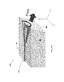
In one aspect, a terahertz quantum cascade laser device for operation via the Cherenkov difference-frequency generation (DFG) scheme is provided. A cross-sectional, side view of an illustrative device 100 is shown in FIG. 1A . The longitudinal dimension of the device is along axis x; the lateral dimension is along axis y, coming out of the plane of the paper. The device 100 includes a substrate 102 having a top substrate surface 104, a bottom substrate surface 106, and an exit facet 108 extending between the top substrate surface 104 and the bottom substrate surface 106 at an angle θtap relative to normal to the top substrate surface 104.
The device 100 further includes a waveguide structure 110 above the top substrate surface 104, the waveguide structure 110 having a top surface 112, a bottom surface 114, a front facet 116 extending between the top surface 112 and the bottom surface 114 and positioned proximate to the exit facet 108 of the substrate 102, and a back facet 118 extending between the top surface 112 and the bottom surface 114 and oppositely facing the front facet 116. The waveguide structure 110 includes a quantum cascade laser structure 120 including a superlattice of quantum wells and barriers, the quantum cascade laser structure 120 configured to generate light including light of a first frequency ω1, light of a second frequency ω2, and light of a third frequency ωTHz, wherein ωTHz=ω1−ω2. In the absence of any distributed feedback grating, the emission wavelengths of the quantum cascade laser structure 120 are (especially at high drives above threshold) spread over relatively wide wavelength ranges, each about a peak wavelength. Thus, the “first frequency ω1” may refer to the frequency at the peak of one range of emission wavelengths and the “second frequency ω2” may refer to the frequency at the peak of another range of emission wavelengths. The waveguide structure 110 is configured to guide the light generated within the quantum cascade laser structure 120 via the inclusion of material layer(s), e.g., cladding layer(s), as further described below.
The device 100 further includes a distributed feedback (DFB) grating layer 122 above the quantum cascade laser structure 120 which is configured to provide additional optical feedback for one or both of light of the first frequency ω1 and light of the second frequency ω2 so as to produce lasing at the first frequency ω1, the second frequency ω2, or both, thereby resulting in laser emission at the third frequency ωTHz at a Cherenkov angle θTHz through the exit facet 108. The DFB grating layer 122 includes one or more grating regions, each grating region including grating elements which periodically alternate in a longitudinal direction across the device, wherein adjacent grating elements have different indices of refraction.
The device 100 further includes a high-reflectivity coating 124 on the front facet 116 of the waveguide structure 110. In this illustrative embodiment, the device 100 also includes a top contact layer 126. In this illustrative embodiment, the back facet 118 is uncoated, although a coating may be included thereon, e.g., an antireflective coating. Similarly, in this illustrative embodiment, the exit facet 108 is uncoated, although a coating such as an antireflective coating may be included thereon.
As will be further described below, through band engineering, the quantum cascade laser structure 120 is configured to generate light including light of at least two different frequencies, ω1 and ω2, via intersubband transitions, as well as light of the third frequency ωTHz, via DFG. In general, Cherenkov emission occurs when the phase velocity of the non-linear polarization wave in a thin slab of non-linear optical material (e.g., the quantum cascade laser structure 120) is faster than the phase velocity of the generated light in the medium surrounding the slab (e.g., the substrate 102). This condition is satisfied when the refractive index nTHz at THz frequencies of the substrate 102 is higher than the group index ng of the mid-IR modes in the quantum cascade laser structure 120. Then, light is emitted at the Cherenkov angle θTHz=cos−1(ng/nTHz) through the bottom surface 114 of the waveguide structure 110 into the substrate 102. The exit facet 108 of the substrate 102 is polished (e.g., mechanically polished) at the angle θtap relative to normal to the top substrate surface 104. The angle θtap may be selected to minimize total internal reflection of the light at the third frequency ωTHz emitted at the Cherenkov angle θTHz and to allow the THz light to emerge from the substrate in a direction approximately parallel with the top surface of the substrate 104 (see FIG. 4 ). The angle θtap for device 100 is about 30°. The angle θtap may be, for example, in the range of from about 10° to about 40° or from about 20° to about 40°.
Various semiconductor materials, e.g., group III-V semiconductor compounds, may be used for the substrate of the disclosed devices. Selection of the particular material depends upon the materials used in the quantum cascade laser structure (as further described below) and the requirement of Cherenkov emission (as described above). In some embodiments, the substrate is composed of undoped or semi-insulating InP.
A perspective view of the device 100 is shown in FIG. 1B . As illustrated in FIG. 1B , the materials of the waveguide structure 100 may be processed (e.g., via inductive plasma etching) to form a ridge, e.g., about 10-25 μm wide (across they axis), on the substrate 102. Additional material layers such as an insulating layer (e.g., SiN) may be formed on the walls of the ridge and the top contact layer 126 may be formed on the ridge (e.g., both via a variety of thin film deposition/growth techniques). The entire device 100 may then be cleaved to form bars, for example, having a length (along the z axis) in the range of from about 1 mm to about 1 cm, from about 1 mm to about 5 mm, e.g., about 2 mm, about 3 mm, about 4 mm, or about 5 mm. The exit facet 108 of the substrate 102 may then be polished at the angle θtap as described above.
As noted above, the quantum cascade laser structure of the disclosed devices includes a superlattice of quantum wells and barriers and is configured to generate light including light of the first frequency ω1, light of the second frequency ω2, and light of the third frequency ωTHz wherein ωTHz=ω1−ω2. The quantum cascade laser structure is configured to exhibit sufficient second-order nonlinear susceptibility in order to support THz radiation based on DFG between light of the first frequency ω1 and light of the second frequency ω2, i.e., THz DFG.
This may be achieved in a variety of ways. By way of illustration, the quantum cascade laser structure may include a first core including multiple stages, each stage including a first bound-to-continuum active region configured to generate light including the light of the first frequency ω1 and a second core including multiple stages, each stage including a second bound-to-continuum active region configured to generate light including light of the second frequency ω2. One or both of the first and second bound-to-continuum active regions are configured to exhibit relatively large second-order nonlinear susceptibility for THz DFG. The term “bound-to-continuum” refers to the mechanism of light generation in the active region under electrical bias. A bound-to-continuum active region is a superlattice of quantum wells and barriers in which light emission occurs via intersubband transitions between one upper energy state, primarily aligned with the ground state in the lower miniband of an injector region of the stage, and a miniband of the active region. FIG. 2A shows a conduction-band diagram under operating bias voltage of one illustrative stage (period) including a bound-to-continuum active region configured to generate light including light of a first frequency ω1. The wavy curves represent the electron wavefunctions. The electron states important for THz DFG are shown in bold and labeled 1 to 3. Electron injection and extraction are labeled. The laser section (i.e., the active region), the injector section, the injector barrier and the extraction barrier of the stage are also labeled. FIG. 2B shows the equivalent energy level diagram for the band structure shown in FIG. 2A . Electron population in the upper laser state is shown with circles.
A suitable quantum cascade laser structure including a first core including multiple stages, each stage including a first bound-to-continuum active region for primarily generating ω1 and a second core including multiple stages, each stage including a second bound-to-continuum active region for primarily generating ω2 is found in K. Vijayraghavan, et al., Nature Comm. 4, 2021 (2013), which is hereby incorporated by reference in its entirety. However, this quantum cascade laser structure may be further optimized to provide mid-IR gain in the 8-10 μm spectral region, rather than the 9-11 μm spectral region.
As another illustration, the quantum cascade laser structure may include a core including multiple stages, each stage including a continuum-to-continuum active region configured to exhibit sufficient second-order nonlinear susceptibility in order to support THz DFG. The term “continuum-to-continuum” also refers to the mechanism of light generation in the active region under electrical bias. A continuum-to-continuum active region is a superlattice of quantum wells and barriers in which light emission occurs via intersubband transitions between two minibands of the active region. (See B. Meng, et al., Appl. Phys. Lett. 107, 111110 (2015), which is hereby incorporated by reference in its entirety.) Thus, a continuum-to-continuum active region generates a range, which may be quite broad, of frequencies (including the first and second frequencies ω1 and ω2) and thus, can generate a range of possible THz frequencies (including the radiation at the third frequency ωTHz). FIG. 3A shows a conduction-band diagram under operating bias voltage of two illustrative stages (periods), each stage including a continuum-to-continuum active region configured to generate light including light of the first frequency ω1, light of the second frequency ω2, and light of the third frequency ωTHz via DFG. The wavy curves represent the electron wavefunctions of the upper laser states and the lower laser states. FIG. 3B shows three upper laser states and three lower laser states of the band structure shown in FIG. 3A which are important for THz DFG. Continuum-to-continuum active regions may be useful to increase the nonlinear conversion efficiency η of the disclosed devices. The nonlinear conversion efficiency η is defined as the ratio of THz power output from the device W(ωTHz) to the product of mid-IR pump power outputs W(ω1)W(ω2) from the device,
η=W(ωTHz)/[W(ω1)W(ω2)]. Simulations may be performed using the slab-waveguide model of Cherenkov THz-DFG emission following the approach described in K. Vijayraghavan, et al., Nature Comm. 4, 2021 (2013) for calculating the nonlinear conversion efficiency η values of the disclosed devices.
The quantum cascade laser structures of the disclosed devices may include various numbers of stages (e.g., 10, 20, 30, 40, 50, 60, etc.) as well as various numbers of cores (e.g., 1, 2, etc.). The quantum cascade laser structures may include additional material layers, e.g., a heat-spreading layer between adjacent cores for lateral heat removal.
Band engineering is used (i.e., selection of the composition, thicknesses, and arrangement of the quantum wells and barriers in the stages of the quantum cascade laser structures, particularly the active regions) to provide the desired mechanism of light generation, the desired first and second frequencies ω1 and ω2 (or range of frequencies) and the desired second-order nonlinear susceptibilities to support THz DFG. The wavelengths of light generated by the quantum cascade laser structures will generally be in the mid-IR range, e.g., from about 5 μm to about 20 μm, in order to provide THz radiation in the frequency range of from about 1 THz to about 6 THz via DFG. This includes embodiments in which the wavelengths of light are in the range of from about 5 μm to about 15 μm, or from about 8 μm to about 11 μm and in which the generated THz radiation can be in the frequency range of from about 1 THz to about 5 THz, or from about 1 THz to about 4 THz. Other illustrative quantum cascade laser structures which may be used (or optimized for use) in the disclosed devices include those described in U.S. Pat. No. 7,974,325 and International Patent Publication WO 2014018599, each of which is hereby incorporated by reference in its entirety.
Various semiconductor materials, e.g., group III-V semiconductor compounds, may be used for the layers of the quantum cascade laser structure of the disclosed devices. Selection of the particular materials is driven, at least in part, by the band engineering considerations described above. By way of illustration, InGaAs/InAlAs heterostructures may be used. As is known in the field, the relative amounts of the elements in such semiconductor compounds may vary, i.e., “InGaAs” encompasses those compositions InxGα1-xAs, wherein x varies from about 0 to about 1. Heat-spreading layers may be composed of InP. Crystal growth methods such as molecular beam epitaxy (MBE) and metal-organic chemical vapor deposition (MOCVD) may be used to form the quantum cascade laser structures.
As noted above, the disclosed devices include a DFB grating layer which is configured to provide optical feedback for one or both of light of the first frequency ω1 and light of the second frequency ω2 so as to produce lasing at the first frequency ω1, the second frequency ω2, or both, i.e., single- or dual single-frequency operation. The DFB grating layer includes one or more grating regions, each grating region including grating elements which periodically alternate in a longitudinal direction across the device, wherein adjacent grating elements have different indices of refraction. In some embodiments, a grating region may be characterized by a periodicity Λ=mλ/(2neff), where m is the grating order, λ is the desired wavelength of light (i.e., light of the first or second frequencies ω1, ω2) from the quantum cascade laser structure and neff is the effective index of refraction of the region for λ. In other words, the grating elements alternate with the periodicity Λ. In some embodiments, m=1. In other embodiments, m=2.
In an alternative configuration, a grating region of periodically alternating grating elements of the DFB grating layer may be configured as a biperiodic binary grating region. Biperiodic binary grating regions are grating regions for which the Fourier transform of the grating region includes two peaks (e.g., a peak corresponding to light of the first frequency ω1 and a peak corresponding to light of the second frequency ω2). Thus, biperiodic binary grating regions provide optical feedback for both light of the first frequency ω1 and light of the second frequency ω2 so as to produce lasing at both the first and second frequencies ω1, ω2. Biperiodic binary grating regions such as those described in T. Hidaka et al., Electron. Lett. 27, pp. 1075-1076 (1991), which is hereby incorporated by reference in its entirety, may be used. Biperiodic binary grating regions (which may be referred to as dual periodicity gratings) such as those described in F. Castellano et al., Applied Physics Letters 106, 011103 (2015), which is hereby incorporated by reference in its entirety, may also be used. An illustrative DFB grating layer 522 including a biperiodic binary grating region 540 is shown in FIG. 5 and is further described below.
With reference back to FIG. 4 , the DFB grating layer 422, whether including two back-to-back distributed feedback gratings as shown in FIG. 4 , or including a single biperiodic binary grating region, is particularly useful with quantum cascade laser structures which include bound-to-continuum active regions.
The grating region(s) of the DFB grating layer of the disclosed devices may be characterized by its length l along the longitudinal axis of the device. As shown in FIG. 4 , a length l1 of the first grating region and a length l2 of the second grating region of the DFB grating layer 422 of the device 100 are labeled. In this illustrative embodiment, the lengths l1 and l2 are substantially equal (i.e., equal, but not necessarily perfectly equal) to one another and are also sufficiently long to substantially span the length of the waveguide structure 110 (i.e., the cavity length). (“Substantially span” has the same meaning with respect to the lengths of the grating regions as compared to the waveguide structure as the phrase “substantially equal.”) However, the lengths l1 and l2 need not be equal. In the illustrative embodiment, l1 is about 2 mm and l2 is about 2 mm (total cavity length ˜4 mm). In other embodiments, the length of a grating region (or the combined lengths of multiple grating regions) spans only a portion of the length of the waveguide structure such that one or more gratingless regions are defined within the DFB grating layer. By “gratingless” it is meant that the region does not include the periodically alternating grating elements. Thus, a gratingless region may be composed of a single type of material, e.g., one of the materials of the grating elements.
By way of illustration, a DFB grating layer 522 including a gratingless region 538 and a biperiodic binary grating region 540 is shown in FIG. 5 . FIG. 5 shows the device 100 of FIG. 1A including the illustrative DFB grating layer 522 (i.e., DFB grating layer 522 is another embodiment of DFB grating layer 122). The substrate 102, exit facet 108, waveguide structure 110, front facet 116, back facet 118, quantum cascade laser structure 120, and high-reflectivity coating 124 are labeled. The back facet 118 is uncoated. The biperiodic binary grating region 540 includes periodically alternating grating elements, two of which are labeled 542, 544. One of the periodic π phase shifts is also labeled 546. Various respective lengths (generally indicated by the 538 bracket and the 540 bracket) of the gratingless region 538 and the biperiodic binary grating region 540 may be used as further described below. In the illustrative embodiment, the length of the gratingless region 538 is about 0.5 mm and the length of the biperiodic binary grating region 540 is about 1.5 mm (total cavity length ˜2 mm). The DFB grating layer 522 is useful for quantum cascade laser structures which include continuum-to-continuum active regions.
In other embodiments, the DFB grating layer of the disclosed devices includes a single grating region, e.g., a single grating region of periodically alternating grating elements characterized by a periodicity Λ=mλ/(2neff) as described above. The single grating region may substantially span the length of the waveguide structure or the single grating region may span only a portion of the waveguide structure so as to define a gratingless region. By way of illustration, a device having a total cavity length of ˜2 mm may include a single grating region having a length of ˜1.5 mm and a single gratingless region having a length of ˜0.5 mm. A DFB grating layer including a single grating region provides optical feedback and lasing for a single frequency of light. This is useful when the device is to be used in an external cavity (EC) configuration, in which case the second frequency of light (exiting the back facet of the device) needed for THz light generation via DFG is selected by the EC. Suitable EC configurations include those in K. Vijayraghavan, et al., Nature Comm. 4, 2021 (2013) and in Y. Jiang, et al., Sci. Rep. 6, 21169 (2016).
The particular configuration of the DFB grating layer, e.g., as determined by the number of grating regions, the type of grating (e.g., periodicity Λ or biperiodic binary), the relative lengths of grating regions and the presence of gratingless regions may be selected, at least in part, to maximize the THz extraction efficiency of the disclosed devices as well as to achieve desired relative values of threshold-current densities Jth for the two desired frequencies of light ω1, ω2, as further described below.
The position of the DFB grating layer with respect to the quantum cascade laser structure is not particularly limited. As shown in FIGS. 1A, 4 and 5 , each of the DFB grating layers is a buried DFB grating layer, i.e., is embedded within the multilayer waveguide structure 110. The DFB grating layer may be disposed on the top surface of the quantum cascade laser structure. However, surface DFB grating layers may be used, disposed on the top surface of the waveguide structure itself. By way of illustration, a surface DFB grating layer may be formed by appropriately configuring the top surfaces of the cap layer 662 and the plasmon layer 660 (see FIG. 6 ) and the bottom surface of the overlying top contact layer 126 (see FIG. 1A ), as further described below.
Various materials, e.g., semiconductor materials, may be used for the DFB grating layer of the disclosed devices. By way of illustration, group III-V semiconductor compounds may be used to form the periodically alternating grating elements wherein adjacent grating elements have different indices of refraction (i.e., different semiconductor compositions). Known techniques may be used to form the DFB grating layer, e.g., e-beam lithography and wet chemical etching. For example, after growing the quantum cascade laser structure, an etch-stopping layer may be formed thereon (e.g., ˜0.1 μm-thick InP). The DFB grating layer may then be formed by forming a layer of a first semiconductor over the etch-stopping layer, etching the layer of the first semiconductor to provide a first set of separated grating elements, and forming a layer of a second semiconductor over and/or in between the first set of separated grating elements to provide a second set of separated grating elements. Selection of the particular materials used for the DFB grating layer depends, at least in part, upon the materials used in the quantum cascade laser structure. In some embodiments, the first semiconductor is InGaAs and the second semiconductor is InP. Surface DFB grating layers may be similarly formed, however, one of the sets of separated grating elements may be composed of a semiconductor or semiconductors (e.g., the cap layer 662 and part of the plasmon layer 660) and the other set of separated grating elements may be composed of a metal or metals (e.g., the top contact layer 126).
The waveguide structure of the disclosed devices includes other material layers, for example, to guide light generated in the quantum cascade laser structure. By way of illustration, the waveguide structure may include an upper cladding layer disposed above the quantum cascade laser structure, and in embodiments, disposed above the DFB grating layer. A lower cladding layer may be disposed under the quantum cascade laser structure. Similarly, other material layers, e.g., current spreading layers, plasmon layers, cap layers, contact layers, etc. may be included in the disclosed devices. Such material layers may or may not be considered to be part of the waveguide structure. A current spreading layer may be disposed under the quantum cascade laser structure, and in some embodiments, under the lower cladding layer. A plasmon layer may be disposed above the upper cladding layer. A cap layer may be disposed above the plasmon layer. A contact layer may be disposed above the cap layer. Various compositions may be used for these additional material layers. By way of illustration, InGaAs may be used for the current spreading layer. InP may be used (at various doping levels) for the cladding layers, plasmon layer and cap layer. Metals, e.g., titanium, gold, etc., may be used for the contact layer(s). Known thin film deposition/growth techniques may be used to form these additional material layers.
As noted above, the disclosed devices further include a high-reflectivity coating on the front facet of the waveguide structure. The high-reflectivity coating is disposed on the front facet, by contrast to conventional devices which do not use such coatings proximate to the exit facet (the facet through which laser emission occurs) in order to avoid blocking laser emission. Instead, conventional devices utilize high-reflectivity coatings on the back facets of waveguide structures. However, as further described below, it has been found that the use of the disclosed high-reflectivity coatings on the front facet of the waveguide structure significantly improves the extraction of THz laser emission from the disclosed devices, and thus, the mid-IR-to-THz conversion efficiencies.
An illustrative high-reflectivity coating 124 is shown in FIG. 1A . The high-reflectivity coating 124 is on the front facet 116 of the waveguide structure 110, rather than the back facet 118. In this embodiment, the back facet 118 is uncoated. A variety of reflective materials (e.g., reflective to mid-infrared light, e.g., 5 μm to 20 μm) may be used for the high-reflectivity coating. The reflectivity to mid-infrared light may be in the range of from about 85% to about 99%. In the illustrative embodiment, the high-reflectivity coating 124 includes an outer layer 136 of gold and an inner layer 137 of YF2 (or Al2O3 or ZnSe). Other similar materials may be used. Various thicknesses for the high-reflectivity coating may be used. In the illustrative embodiment, the outer layer 136 is about 100 nm thick and the inner layer 137 is about 200 nm thick. Various thin film deposition/growth techniques (e.g., evaporation) may be used to form the high-reflectivity coating.
A cross-sectional view (facet view) of a portion of an illustrative device 600 is shown in FIG. 6 . The device 600 includes a substrate 602 (semi-insulating InP) and a waveguide structure 610. The waveguide structure 610 includes a quantum cascade laser structure 620 including a first (lower) core 650 including multiple stages (20), each stage including a first bound-to-continuum active region configured to generate light including light of the first frequency ω1 (λ1=8.2 μm) and a second (upper) core 652 including multiple stages (26), each stage including a second bound-to-continuum active region configured to generate light including the light of the second frequency ω2 (λ2=9.2 μm). Both of the first and second bound-to-continuum active regions are formed from InGaAs/InAlAs and are configured to exhibit relatively large second-order nonlinear susceptibility for THz DFG. The bound-to-continuum active regions used were those described in K. Vijayraghavan, et al., Nature Comm. 4, 2021 (2013), but optimized to provide mid-IR gain in the 8-10 μm spectral regional region. In this illustrative embodiment, the upper core 652 further includes multiple (6) stages including the first bound-to-continuum active region. Mixing stages of different emission wavelengths is useful to achieve the desired relative values of threshold-current densities Jth for the two desired frequencies of light ω1, ω2 (e.g., Jth values for the two desired frequencies of light that are within about ±10%). In addition, a ˜0.5 μm-thick heat-spreading layer 654 separates the upper and lower cores 652, 650.
The device 600 further includes a DFB grating layer 622 above the quantum cascade laser structure 620 which is configured to provide optical feedback for both 8.2 μm and 9.2 μm wavelengths. The DFB grating layer 422 of FIG. 4 may be used, i.e., including two back-to-back distributed feedback gratings (or alternatively, the DFB grating layer 622 may include a single biperiodic binary grating region) spanning the length of the waveguide structure (total cavity length ˜4 mm). The waveguide structure 610 further includes a lower cladding layer 656 and an upper cladding layer 658. The device 600 further includes a plasmon layer 660 and a cap layer 662. The device 600 further includes a current spreading layer 664. The configuration of device 600 otherwise follows that described above for device 100 of FIG. 1A , i.e., high-reflectivity coating on the front facet, beveled substrate, uncoated back facet. The frequency of laser emission (ωTHz) of the device 600 is about 4 THz.
The extraction efficiency of THz light from the device 600 either having the DFB grating layer 422 of FIG. 4 or the single biperiodic binary grating region were calculated and compared to the extraction efficiency of a comparative device having uncoated front facets. The devices were modeled using coupled-mode theory (CMT). (See R. J. Noll and S. H. Macomber, IEEE J. Quantum Electron. 26, pp. 456-466 (1990).) Coupled-mode theory can separate the field intensity into forward (R) and backward (S) traveling waves. The calculations for the extraction efficiency were performed as followed. All R and S fields were normalized according to:
∫0 L |R x|2 +|S x|2 dz=1Equation 1
where L is the length of the device. The degree of extraction of generated THz light from the front facet side, which is called S (output) coupling, was calculated by:
∫0 L |R x|2 +|S x|2 dz=1
where L is the length of the device. The degree of extraction of generated THz light from the front facet side, which is called S (output) coupling, was calculated by:
where zmax, the maximum position for which THz light is emitted through the exit facet, is calculated based on the substrate thickness, tsub, Cherenkov angle θTHz, and angle θtap, by:
z max =t sub(tan θtap+cot θTHz)
The angles and dimensions have been labeled in FIG. 1A . αsub is the THz radiation absorption coefficient in the substrate. In some embodiments, θTHz=20°, θtap=30°, αsub=15 cm−1 for an InP substrate at about 4 THz. For an InP substrate thickness (tsub) of about 350 μm, the maximum longitudinal position, zmax, is about 1.16 mm. For a substrate thickness of about 500 μm, the zmax value is about 1.66 mm.
By contrast to the comparative device, as illustrated in FIGS. 9A-9B , the extraction efficiency is significantly greater for the device 600 of FIG. 6 having the single biperiodic binary grating region spanning the length of the waveguide structure and the front facet coated with the high-reflectivity (HR) coating/uncoated back facet. In this case, there is very good overlap between the 8.2 μm and 9.2 μm S waves close to the front facet. In turn, the extraction efficiency of the device 600 is about 2 times greater than the comparative device (FIGS. 8A-8B ). The improvement in extraction efficiency is observed for most combinations of Δφb and Δφf values.
As illustrated by FIGS. 10A-10B , the extraction efficiency for the device 600 of FIG. 6 having the DFB grating layer 422 of FIG. 4 (two back-to-back grating regions) is even greater as compared to the comparative device (FIGS. 8A-8B ). As noted above, the front facet is coated with the HR coating and the back facet is uncoated. In this case, the overlap between the 8.2 μm and 9.2 μm S waves close to the HR coated front facet is even stronger than for the device 600 with the single biperiodic binary grating region (FIGS. 9A-9B ). The extraction efficiency of the device 600 having the DFB grating layer 422 of FIG. 4 is about 3 times greater than the comparative device (FIGS. 8A-8B ).
A cross-sectional view of a portion of another illustrative device 700 is shown in FIG. 7 . The device 700 includes a substrate 702 (semi-insulating InP) and a waveguide structure 710. The waveguide structure 710 includes a quantum cascade laser structure 720 including a first (lower) core 750 including multiple stages (29), each stage including a first continuum-to-continuum active region and a second (upper) core 752 including multiple stages (29), each stage including a second continuum-to-continuum active region. As noted above, a continuum-to-continuum active region can generate a range of frequencies (including the first and second frequencies ω1 and ω2). In the illustrative embodiment, the configurations of the lower core 750 and the upper core 752 are the same (although they need not be) and both generate light including light of the first frequency ω1 (λ1=8.55 μm) and light of the second frequency ω2 (λ2=9.65 μm). Both of the first and second continuum-to-continuum active regions are formed from InGaAs/InAlAs and are configured to exhibit relatively large second-order nonlinear susceptibility for THz DFG. The continuum-to-continuum active regions used were those disclosed in B. Meng, et al., Appl. Phys. Lett. 107, 111110 (2015). In this illustrative embodiment, a ˜0.3 μm-thick heat-spreading layer 754 separates the upper and lower cores 752, 750.
The device 700 further includes a DFB grating layer 722 above the quantum cascade laser structure 720 which is configured to provide optical feedback for both 8.55 μm and 9.65 μm. The DFB grating layer 722 is configured as the DFB grating layer 522 of FIG. 5 , i.e., including a ˜0.5 mm gratingless region adjacent to a ˜1.5 mm biperiodic binary grating region (total cavity length ˜2 mm). The waveguide structure 710 further includes a 2 μm-thick lower cladding layer 756 (doped to ˜2×1016 cm−3) and a ˜4 μm-thick upper cladding layer 758 (doped to ˜2×1016 cm−3). The device 700 further includes a ˜300 nm-thick plasmon layer 760 (doped to ˜3×1018 cm−3) and a ˜10 nm-thick cap layer 762 (doped to ˜2×1019 cm−3). In this illustrative embodiment, the device 700 further includes a ˜200 nm-thick current spreading layer 764 (doped to ˜1018 cm−3).
As has been illustrated in FIG. 1A , the front facet of the device 700 includes a high-reflectivity coating of ˜100 nm-thick Au outer layer/˜200 nm-thick YF2 (or Al2O3) inner layer. The back facet may be uncoated or may include an antireflective coating of YF2 and ZnSe. The substrate 702 is polished to θtap ˜30°. The exit facet for THz radiation may be uncoated or may include an antireflective (to THz radiation) coating of SiO2. The frequency of laser emission (ωTHz) of the device 700 is about 3.7 THz. This illustrative embodiment gives both a large amount of power (due to the large number of stages) and is optimized for minimum THz absorption loss; thus, providing the high values of mid-IR-to-THz conversion efficiency, η(˜8 mW/W2 at 3.7 THz). The mid-IR-to-THz conversion efficiencies of the device 600 of FIG. 6 (which is based on bound-to-continuum active regions) is ˜1.7 mW/W2.
Together, FIGS. 8A-8B, 9A-9B, 10A-10B, 11A-11B and 12A-12B demonstrate that, as compared to the conventional approach of using uncoated front facets, the use of the disclosed high-reflectivity coatings on the front facets of the disclosed waveguide structures as well as combined with the disclosed DFB grating layers greatly improves the THz extraction efficiency of the disclosed devices. This, in turn, increases the mid-IR-to-THz conversion efficiency, η, by the same factor, and thus, also increases the average THz power of the disclosed devices.
The disclosed devices may be configured as single-element devices (e.g., as illustrated in FIGS. 1A-1B, 6 and 7 ). Alternatively, the disclosed devices may be configured as phase-locked array devices in order to increase the volume of mid-IR emitting material, while maintaining coherence across large apertures (e.g., ˜100 μm) and thus, to scale the generated THz power. In addition, the THz light generated from a phase-locked array will be a plane wave, given that the emitting aperture is comparable to the THz-radiation wavelength, rather than the conical wave that is being emitted from a single ridge-guide device (see FIG. 1B ). In turn, the THz radiation collection efficiency when using a 100 μm-wide phase-locked array is at least twice that when using a single-ridge device, and the collected THz power from an array scales by twice the ratio of array and ridge-guide emitting apertures.
The phase-locked array configuration may be implemented by including in the devices described above, a plurality of laterally-spaced (in the direction of they axis, perpendicular to the xz axes of FIG. 1A ) trench regions extending transversely, at least partially into the quantum cascade laser structure (e.g., partially into an upper core, completely through the upper core, completely through the upper core and partially into the heat-spreading layer, etc.) of the waveguide structure. Each trench region may include a lower trench layer including a semi-insulating material and an upper trench layer including a material having a refractive index that is higher than the refractive index of the semi-insulating material. The trench regions define interelement regions separated by element regions in the phase-locked array. The phase-locked array device is characterized in that the effective refractive index of the fundamental transverse mode supported in the interelement regions is higher than the effective refractive index of the fundamental transverse mode supported in the element regions. The phase-locked array device is further characterized in that the device is configured to produce an in-phase array mode meeting the lateral resonance condition in which there is strong coupling via leaky waves between all of the element regions. In other words, the array elements are coupled via resonant leaky-wave coupling in what constitutes a high-index-contrast (HC) photonic-crystal (PC) structure. Phase-locked array devices including quantum cascade laser structures are described in U.S. Pat. Nos. 8,259,767 and 8,428,093, each of which is hereby incorporated by reference in its entirety.
A cross-sectional view of a portion of a phase-locked array device 1300 is shown in FIG. 13A . Two element regions 1370, 1372 are separated by an interelement region 1374 defined by a trench region 1376. Aside from the inclusion a plurality of trench regions and additional material layers formed in and over the plurality of trench regions, the multilayer structure of the device 1300 is the same as that of the single-element device 700 shown in FIG. 7 . Thus, the same reference labels are used as described above. However, other quantum cascade laser structures and other DFB grating layers may be used as described above. In addition, additional, fewer, or different material layers may be included in the multilayer structure as described above. In this illustrative embodiment, the trench region 1376 extends partially into the upper core 752 of the quantum cascade laser structure 720 (and thus, partially into the waveguide structure 710). The trench region 1376 includes a lower trench layer 1378 of a semi-insulating material (e.g., semi-insulating InP) and an upper trench layer 1380 of a material of a higher refractive index (e.g., InGaAs) than the semi-insulating material. Additional material layers may be formed in the trench regions as well as over the rest of the multilayer structure, e.g., a layer of a light-absorbing material 1382 (e.g., Ti) and a layer of metal 1384 (e.g., Au). The phase-locked array device 1300 is otherwise configured as described above with respect to device 100 of FIG. 1A , i.e., including a high-reflectivity coating on the front facet and a beveled substrate 702. The back facet and the exit facet may be uncoated or one or both may be coated with an antireflective coating as described above.
A perspective view of the phase-locked array device 1300 is shown in FIG. 13B . The phase-locked array device 1300 is shown processed similarly to the device 100 of FIG. 1B . The number of element regions, the number of interelement regions, and their respective widths may vary. FIG. 13B shows 5 element regions, each about 15 μm wide. The total width of the device 1300 is about 100 μm. The exit facet 1308 and substrate 702 are labeled. The generated THz power from the device 1300 will increase fivefold compared to a comparative 15 μm-wide ridge device (i.e., single-element device). Furthermore, as shown in FIG. 13B , the THz light generated from the device 1300 will be a plane wave, given that the emitting aperture is comparable to the THz-radiation wavelength, rather than the conical wave that is being emitted from a single ridge-guide device (see FIG. 1B ). It has been calculated that the THz radiation collection efficiency when using a 100 μm-wide phase-locked array such as that of FIG. 13B is at least twice that when using a single-ridge device. Thus, using a phase-locked array increases the usable THz-radiation output by at least an order of magnitude.
Fabrication of the phase-locked array device 1300 first follows that described above with respect to the formation of the multilayer structure of the single-element devices. Next, the interelement regions may be formed by etch-and-regrowth as described in J. D. Kirch, C.-C Chang, C. Boyle et al, Appl. Phys. Lett. 106, 061113 (2015), which is hereby incorporated by reference in its entirety. The interelement regions may then be proton-implanted in order to confine the current only to the element regions. After implantation, additional processing follows that described in J. D. Kirch, C.-C Chang, C. Boyle et al, Appl. Phys. Lett. 106, 061113 (2015), resulting in devices having the cross-section shown in FIG. 13A . Additional processing steps, e.g., cleaving, facet coating, substrate polishing, etc., may then be conducted as described above to complete the devices.
As shown in FIG. 16 , the in-phase-mode Jth values are ˜2.55 kA/cm2 and ˜2.3 kA/cm2 at 9.3 μm and 8.9 μm wavelengths, respectively. The structure has the same high built-in index step, Δn, value: 0.06, between interelement and element regions, at λ=8.9 μm and 9.3 μm wavelengths. Mode 8 is strongly favored to lase over a 1.60 μm-wide region in S (i.e., from 7.5 μm to 9.1 μm); in that, over that range the Jth values of the competing modes, array modes 7 and 9, are ≧40% higher than the mode-8 Jth value. Thus, while for 1.5 THz vs. 3.7 THz one obtains a lower mid-IR-to-THz conversion efficiency, the fabrication tolerance for obtaining stable, in-phase array-mode operation is 2.7 times larger than that needed to at 3.7 THz frequency. (The fabrication-tolerance window is inversely proportional with the needed wavelength difference.) Indeed the ratio of the wavelength differences needed for generating 3.7 and 1.5 THz is 1.1 μm/0.4 μm=2.75; basically the 2.7 ratio mentioned above.
Together, FIGS. 14-17 show that the disclosed phase-locked array devices provide significantly higher powers at room temperature as compared to conventional Cherenkov THz DFG-QCLs. (See Background.) As described above, this is attributed, at least in part, to the use of the disclosed high-reflectivity coatings on the front facets of the disclosed waveguide structures as well as in combination with the disclosed DFB grating layers. Further increases in power (e.g., ˜50 mW average THz power at 3-4 THz at room temperature) may be achieved by increasing the cavity length (e.g., to ˜5 mm) and by transferring and bonding the devices to high-resistivity Si substrates which have significantly lower loss at 3-4 THz as compared to semi-insulating InP.
By way of another illustration, another phase-locked array device having a structure similar to the phase-locked array device 1300 of FIG. 13A may be formed, but based on the multilayer structure of FIG. 6 (i.e., just as the phase-locked array device 1300 of FIG. 13A is based on the multilayer structure of FIG. 7 ). FIG. 18 plots the threshold-current density Jth as a function of interelement width S for such a device having 5 element regions and multiple stages including a first bound-to-continuum active region and multiple stages including a second bound-to-continuum active region in the cores 650, 652 of the quantum cascade laser structure 620, respectively. The DFB grating layer 622 used was similar to that used in FIGS. 10A, 10B ; i.e., two back-to-back 1st-order grating regions for optical feedback at 8.2 μm and 9.2 μm wavelengths, respectively (see also the DFB grating layer 422 of FIG. 4). The front facet was coated with a high-reflectivity coating and the back facet was uncoated. The phase-locked array device has a high built-in index step, Δn, values between interelement and element regions, at both λ=8.2 μm (Δn=0.093) and λ=9.2 μm (Δn=0.081). The mode-8 Jh value is ˜3.8 kA/cm2 and is about the same at both wavelengths.
Unless otherwise indicated, the semiconductor materials disclosed herein may be doped or undoped.
The word “illustrative” is used herein to mean serving as an example, instance, or illustration. Any aspect or design described herein as “illustrative” is not necessarily to be construed as preferred or advantageous over other aspects or designs. Further, for the purposes of this disclosure and unless otherwise specified, “a” or “an” means “one or more”.
The foregoing description of illustrative embodiments of the disclosure has been presented for purposes of illustration and of description. It is not intended to be exhaustive or to limit the disclosure to the precise form disclosed, and modifications and variations are possible in light of the above teachings or may be acquired from practice of the disclosure. The embodiments were chosen and described in order to explain the principles of the disclosure and as practical applications of the disclosure to enable one skilled in the art to utilize the disclosure in various embodiments and with various modifications as suited to the particular use contemplated. It is intended that the scope of the disclosure be defined by the claims appended hereto and their equivalents.
Claims (20)
1. A terahertz quantum cascade laser device comprising:
a substrate having a top substrate surface, a bottom substrate surface, and an exit facet extending between the top substrate surface and the bottom substrate surface at an angle θtap relative to normal to the top substrate surface;
a waveguide structure above the top substrate surface, the waveguide structure having a top surface, a bottom surface, a front facet extending between the top surface and the bottom surface and positioned proximate to the exit facet of the substrate, and a back facet extending between the top surface and the bottom surface and oppositely facing the front facet, the waveguide structure comprising
a quantum cascade laser structure comprising a superlattice of quantum wells and barriers, the quantum cascade laser structure configured to generate light comprising light of a first frequency ω1, light of a second frequency ω2, and light of a third frequency ωTHz, wherein ωTHz=ω1−ω2,
an upper cladding layer above the quantum cascade laser structure, and
a lower cladding layer below the quantum cascade laser structure;
a distributed feedback (DFB) grating layer above the quantum cascade laser structure, the DFB grating layer comprising one or more grating regions, each grating region comprising grating elements which periodically alternate in a longitudinal direction across the device, wherein adjacent grating elements have different indices of refraction, the DFB grating layer configured to provide optical feedback for one or both of the light of the first frequency ω1 and the light of the second frequency ω2 and to produce lasing at one or both of the first frequency ω1 and the second frequency ω2, thereby resulting in laser emission at the third frequency ωTHz at a Cherenkov angle θTHz through the bottom surface of the waveguide structure into the substrate and exiting the substrate through the exit facet; and
a high-reflectivity coating on the front facet of the waveguide structure.
2. The device of claim 1 , wherein the back facet is uncoated or coated with an antireflective coating.
3. The device of claim 1 , wherein the quantum cascade laser structure comprises a first core comprising multiple stages, each stage comprising a first bound-to-continuum heterostructure configured to generate the light of the first frequency ω1 and a second core comprising multiple stages, each stage comprising a second bound-to-continuum heterostructure configured to generate the light of the second frequency ω2.
4. The device of claim 1 , wherein the quantum cascade laser structure comprises one or more cores comprising multiple stages, each stage comprising a continuum-to-continuum heterostructure configured to generate the light of the first frequency ω1 and the light of the second frequency ω2.
5. The device of claim 4 , wherein the quantum cascade laser structure comprises two cores, each comprising multiple stages, each stage comprising the continuum-to-continuum heterostructure.
6. The device of claim 1 , wherein the quantum cascade laser structure comprises InGaAs/InAlAs heterostructures.
7. The device of claim 1 , wherein the DFB grating layer is configured to provide optical feedback for only one of the light of the first frequency ω1 and the light of the second frequency ω2 and to produce lasing at only one of the first frequency ω1 and the second frequency ω2.
8. The device of claim 1 , wherein the DFB grating layer is a buried DFB grating layer.
9. The device of claim 1 , wherein at least one of the grating regions is characterized by a periodicity Λ=mλ/(2neff), where m is the grating order, λ is the wavelength corresponding to the light of the first frequency ω1 or the light of the second frequency ω2 and neff is the effective index of refraction of the quantum cascade laser structure for λ.
10. The device of claim 9 , wherein the DFB grating layer comprises a single grating region characterized by the periodicity Λ such that the DFB grating layer provides optical feedback for only one of the light of the first frequency ω1 and the light of the second frequency ω2 to produce lasing at only one of the first frequency ω1 and the second frequency ω2.
11. The device of claim 9 , wherein the DFB grating layer comprises two grating regions, wherein one of the grating regions is characterized by a first periodicity Λ1 and a length l1, and the other of the grating regions is characterized by a second periodicity Λ2 and a length l2.
12. The device of claim 11 , wherein the sum of l1 and l2 is substantially the same as the length of the waveguide structure.
13. The device of claim 1 , wherein at least one of the grating regions is a biperiodic binary grating region.
14. The device of claim 13 , wherein the length of the biperiodic binary grating region is substantially the same as the length of the waveguide structure.
15. The device of claim 1 , wherein the length of the one or more grating regions is selected to define at least one gratingless region in the DFB grating layer.
16. The device of claim 15 , wherein the DFB grating layer comprises a gratingless region and a single grating region which is a biperiodic binary grating region.
17. The device of claim 16 , wherein the back facet is uncoated.
18. The device of claim 15 , wherein the DFB grating layer comprises a gratingless region, a biperiodic binary grating region, and a grating region characterized by a periodicity Λ=mλ/(2neff), where m is the grating order, λ is the wavelength corresponding to the light of the first frequency ω1 or the light of the second frequency ω2 and neff is the effective index of refraction of the quantum cascade laser structure for λ.
19. The device of claim 15 , wherein the back facet is coated with an antireflective coating.
20. The device of claim 1 , wherein the device is configured as a phase-locked array comprising a plurality of laterally-spaced trench regions extending transversely, at least partially into the quantum cascade laser structure, each trench region comprising a lower trench layer comprising a semi-insulating material and an upper trench layer comprising a material having a refractive index that is higher than the refractive index of the semi-insulating material, wherein the trench regions define interelement regions separated by element regions in the array,
wherein the device is characterized in that the effective refractive index of the fundamental transverse mode supported in the interelement regions is higher than the effective refractive index of the fundamental transverse mode supported in the element regions, and further characterized in that the device is configured to produce an in-phase array mode meeting the lateral resonance condition in which there is strong coupling via leaky waves between all of the element regions in the array.
Priority Applications (1)
| Application Number | Priority Date | Filing Date | Title |
|---|---|---|---|
| US15/145,951 US9742151B1 (en) | 2016-05-04 | 2016-05-04 | Terahertz quantum cascade lasers |
Applications Claiming Priority (1)
| Application Number | Priority Date | Filing Date | Title |
|---|---|---|---|
| US15/145,951 US9742151B1 (en) | 2016-05-04 | 2016-05-04 | Terahertz quantum cascade lasers |
Publications (1)
| Publication Number | Publication Date |
|---|---|
| US9742151B1 true US9742151B1 (en) | 2017-08-22 |
Family
ID=59581660
Family Applications (1)
| Application Number | Title | Priority Date | Filing Date |
|---|---|---|---|
| US15/145,951 Active US9742151B1 (en) | 2016-05-04 | 2016-05-04 | Terahertz quantum cascade lasers |
Country Status (1)
| Country | Link |
|---|---|
| US (1) | US9742151B1 (en) |
Cited By (4)
| Publication number | Priority date | Publication date | Assignee | Title |
|---|---|---|---|---|
| US20180069374A1 (en) * | 2016-09-05 | 2018-03-08 | Kabushiki Kaisha Toshiba | Terahertz quantum cascade laser device |
| RU181198U1 (en) * | 2017-12-27 | 2018-07-05 | федеральное государственное автономное образовательное учреждение высшего образования "Санкт-Петербургский национальный исследовательский университет информационных технологий, механики и оптики" (Университет ИТМО) | Heterostructure of a quantum cascade laser |
| US20190115717A1 (en) * | 2017-10-17 | 2019-04-18 | Truelight Corporation | Structure And Fabricating Method Of Distributed Feedback Laser |
| JP2019091838A (en) * | 2017-11-16 | 2019-06-13 | 株式会社東芝 | Surface-emission quantum cascade laser |
Citations (7)
| Publication number | Priority date | Publication date | Assignee | Title |
|---|---|---|---|---|
| US5926493A (en) * | 1997-05-20 | 1999-07-20 | Sdl, Inc. | Optical semiconductor device with diffraction grating structure |
| US6175581B1 (en) * | 1997-08-05 | 2001-01-16 | Nec Corporation | Distributed feedback semiconductor laser |
| US7974325B2 (en) | 2007-03-16 | 2011-07-05 | President And Fellows Of Harvard College | Methods and apparatus for generating terahertz radiation |
| US8259767B2 (en) | 2009-12-16 | 2012-09-04 | Wisconsin Alumni Research Foundation | High-power quantum cascade lasers with active-photonic-crystal structure |
| US20120230358A1 (en) * | 2011-03-11 | 2012-09-13 | Wisconsin Alumni Research Foundation | High-power quantum cascade lasers with active-photonic-crystal structure for single, in-phase mode operation |
| WO2014018599A1 (en) | 2012-07-24 | 2014-01-30 | Board Of Regents, The University Of Texas System | Terahertz quantum cascade laser with difference-frequency generation |
| US9509123B2 (en) * | 2014-10-21 | 2016-11-29 | Board Of Regents The University Of Texas System | Generating terahertz frequency combs from quantum cascade lasers using nonlinear frequency mixing |
-
2016
- 2016-05-04 US US15/145,951 patent/US9742151B1/en active Active
Patent Citations (8)
| Publication number | Priority date | Publication date | Assignee | Title |
|---|---|---|---|---|
| US5926493A (en) * | 1997-05-20 | 1999-07-20 | Sdl, Inc. | Optical semiconductor device with diffraction grating structure |
| US6175581B1 (en) * | 1997-08-05 | 2001-01-16 | Nec Corporation | Distributed feedback semiconductor laser |
| US7974325B2 (en) | 2007-03-16 | 2011-07-05 | President And Fellows Of Harvard College | Methods and apparatus for generating terahertz radiation |
| US8259767B2 (en) | 2009-12-16 | 2012-09-04 | Wisconsin Alumni Research Foundation | High-power quantum cascade lasers with active-photonic-crystal structure |
| US20120230358A1 (en) * | 2011-03-11 | 2012-09-13 | Wisconsin Alumni Research Foundation | High-power quantum cascade lasers with active-photonic-crystal structure for single, in-phase mode operation |
| US8428093B2 (en) | 2011-03-11 | 2013-04-23 | Wisconsin Alumni Research Foundation | High-power quantum cascade lasers with active-photonic-crystal structure for single, in-phase mode operation |
| WO2014018599A1 (en) | 2012-07-24 | 2014-01-30 | Board Of Regents, The University Of Texas System | Terahertz quantum cascade laser with difference-frequency generation |
| US9509123B2 (en) * | 2014-10-21 | 2016-11-29 | Board Of Regents The University Of Texas System | Generating terahertz frequency combs from quantum cascade lasers using nonlinear frequency mixing |
Non-Patent Citations (6)
| Title |
|---|
| Botez, D., et al., Temperature sensitivity of the electro-optical characteristics for mid-infrared (λ=3-16 μm)-emitting quantum cascade lasers, J. Phys. D: Appl. Phys. 49 (2016) 043001: doi:10.1088/0022-3727/49/4/043001, Dec. 15, 2015, pp. 1-33. |
| Gowen, A., et al., Terahertz time domain spectroscopy and imaging: Emerging techniques for food process monitoring and quality control, Trends in Food Science & Technology, vol. 25, Issue 1, May 2012, pp. 40-46. |
| Hidaka, T. and Hatano, Y., Simultaneous Two Wave Oscillation LD Using Biperiodic Binary Grating, Electronics Letters, vol. 27 No. 12, Jun. 6, 1991, pp. 1075-1076. |
| Kirch, J., et al., Highly temperature insensitive, low threshold-current density (λ=8.7-8.8μm) quantum cascade lasers, Appl. Phys. Lett. 106, 151106 (2015); doi.org/10.1063/1.4917499, Apr. 15, 2015, pp. 151106-1-151106-5. |
| Meng, B., et al., Broadly continuously tunable slot waveguide quantum cascade lasers based on a continuum-to-continuum active region design, Applied Physics Letters 107, 111110 (2015); doi:10.1063/1.4931444, Sep. 18, 2015, pp. 111110-1-111110-5. |
| Vijayraghavan, K., et al., Broadly tunable terahertz generation in mid-infrared quantum cascade lasers, Nature Communications 4, Article No. 2021: doi:10,1038/ncomms3021, Jun. 17, 2013, pp. 1-7. |
Cited By (6)
| Publication number | Priority date | Publication date | Assignee | Title |
|---|---|---|---|---|
| US20180069374A1 (en) * | 2016-09-05 | 2018-03-08 | Kabushiki Kaisha Toshiba | Terahertz quantum cascade laser device |
| US10290995B2 (en) * | 2016-09-05 | 2019-05-14 | Kabushiki Kaisha Toshiba | Terahertz quantum cascade laser device |
| US20190115717A1 (en) * | 2017-10-17 | 2019-04-18 | Truelight Corporation | Structure And Fabricating Method Of Distributed Feedback Laser |
| US10581223B2 (en) * | 2017-10-17 | 2020-03-03 | Truelight Corporation | Structure and fabricating method of distributed feedback laser |
| JP2019091838A (en) * | 2017-11-16 | 2019-06-13 | 株式会社東芝 | Surface-emission quantum cascade laser |
| RU181198U1 (en) * | 2017-12-27 | 2018-07-05 | федеральное государственное автономное образовательное учреждение высшего образования "Санкт-Петербургский национальный исследовательский университет информационных технологий, механики и оптики" (Университет ИТМО) | Heterostructure of a quantum cascade laser |
Similar Documents
| Publication | Publication Date | Title |
|---|---|---|
| Belkin et al. | New frontiers in quantum cascade lasers: high performance room temperature terahertz sources | |
| US6560259B1 (en) | Spatially coherent surface-emitting, grating coupled quantum cascade laser with unstable resonance cavity | |
| US7457340B2 (en) | High coherent power, two-dimensional surface-emitting semiconductor diode array laser | |
| Walpole | Semiconductor amplifiers and lasers with tapered gain regions | |
| US5509025A (en) | Unipolar semiconductor laser | |
| US5570386A (en) | Semiconductor laser | |
| US20080310470A1 (en) | Broadband semiconductor laser | |
| US9711948B2 (en) | Terahertz quantum cascade laser implementing a {hacek over (C)}erenkov difference-frequency generation scheme | |
| US9742151B1 (en) | Terahertz quantum cascade lasers | |
| Patchell et al. | Specifying the wavelength and temperature tuning range of a Fabry-Perot laser containing refractive index perturbations | |
| CN105720479A (en) | High-speed semiconductor laser with beam diffusion structure | |
| US6885686B2 (en) | High coherent power, two-dimensional surface-emitting semiconductor diode array laser | |
| US6940639B1 (en) | Phase matched parametric light generation in monolithically integrated intersubband optical devices | |
| US20100309942A1 (en) | Quantum Cascade Lasers (QCLs) Configured to Emit Light Having a Wavelength in the 2.5 - 3.8 Micrometer Band | |
| US20120230358A1 (en) | High-power quantum cascade lasers with active-photonic-crystal structure for single, in-phase mode operation | |
| US6810054B2 (en) | Mode-limiting diode laser structure | |
| Vizbaras et al. | Room-Temperature $\lambda\approx 2.7~\mu {\rm m} $ Quantum Cascade Laser Sources Based on Intracavity Second-Harmonic Generation | |
| Tredicucci et al. | Advances in THz quantum cascade lasers: fulfilling the application potential | |
| US7010010B2 (en) | Broadband cascade light emitters | |
| Ledentsov et al. | Novel approaches to semiconductor lasers | |
| Mahler et al. | Quantum cascade laser: a compact, low cost, solid-state source for plasma diagnostics | |
| Austerer et al. | Second-harmonic generation in GaAs-based quantum-cascade lasers | |
| WO2023135629A1 (en) | Semiconductor laser and module element | |
| Hashimoto et al. | Mid-infrared quantum cascade laser integrated with distributed bragg reflector | |
| Morozov et al. | Nonlinear-optical frequency conversion in a dual-wavelength vertical-external-cavity surface-emitting laser |
Legal Events
| Date | Code | Title | Description |
|---|---|---|---|
| AS | Assignment |
Owner name: WISCONSIN ALUMNI RESEARCH FOUNDATION, WISCONSIN Free format text: ASSIGNMENT OF ASSIGNORS INTEREST;ASSIGNORS:BOTEZ, DAN;SIGLER, CHRISTOPHER;EARLES, THOMAS;AND OTHERS;SIGNING DATES FROM 20160518 TO 20160520;REEL/FRAME:039100/0986 |
|
| STCF | Information on status: patent grant |
Free format text: PATENTED CASE |
|
| CC | Certificate of correction | ||
| MAFP | Maintenance fee payment |
Free format text: PAYMENT OF MAINTENANCE FEE, 4TH YR, SMALL ENTITY (ORIGINAL EVENT CODE: M2551); ENTITY STATUS OF PATENT OWNER: SMALL ENTITY Year of fee payment: 4 |