US9738485B1 - Apparatus and method for spooling wire - Google Patents
Apparatus and method for spooling wire Download PDFInfo
- Publication number
- US9738485B1 US9738485B1 US14/659,165 US201514659165A US9738485B1 US 9738485 B1 US9738485 B1 US 9738485B1 US 201514659165 A US201514659165 A US 201514659165A US 9738485 B1 US9738485 B1 US 9738485B1
- Authority
- US
- United States
- Prior art keywords
- flange assembly
- assembly
- outer flange
- supporting walls
- walls
- Prior art date
- Legal status (The legal status is an assumption and is not a legal conclusion. Google has not performed a legal analysis and makes no representation as to the accuracy of the status listed.)
- Active, expires
Links
Images


Classifications
-
- B—PERFORMING OPERATIONS; TRANSPORTING
- B65—CONVEYING; PACKING; STORING; HANDLING THIN OR FILAMENTARY MATERIAL
- B65H—HANDLING THIN OR FILAMENTARY MATERIAL, e.g. SHEETS, WEBS, CABLES
- B65H49/00—Unwinding or paying-out filamentary material; Supporting, storing or transporting packages from which filamentary material is to be withdrawn or paid-out
- B65H49/18—Methods or apparatus in which packages rotate
- B65H49/20—Package-supporting devices
- B65H49/32—Stands or frameworks
- B65H49/324—Constructional details
-
- B—PERFORMING OPERATIONS; TRANSPORTING
- B65—CONVEYING; PACKING; STORING; HANDLING THIN OR FILAMENTARY MATERIAL
- B65H—HANDLING THIN OR FILAMENTARY MATERIAL, e.g. SHEETS, WEBS, CABLES
- B65H75/00—Storing webs, tapes, or filamentary material, e.g. on reels
- B65H75/02—Cores, formers, supports, or holders for coiled, wound, or folded material, e.g. reels, spindles, bobbins, cop tubes, cans, mandrels or chucks
- B65H75/04—Kinds or types
- B65H75/08—Kinds or types of circular or polygonal cross-section
- B65H75/14—Kinds or types of circular or polygonal cross-section with two end flanges
- B65H75/146—Kinds or types of circular or polygonal cross-section with two end flanges with at least one intermediate flange between the two end flanges
-
- B—PERFORMING OPERATIONS; TRANSPORTING
- B65—CONVEYING; PACKING; STORING; HANDLING THIN OR FILAMENTARY MATERIAL
- B65H—HANDLING THIN OR FILAMENTARY MATERIAL, e.g. SHEETS, WEBS, CABLES
- B65H49/00—Unwinding or paying-out filamentary material; Supporting, storing or transporting packages from which filamentary material is to be withdrawn or paid-out
- B65H49/18—Methods or apparatus in which packages rotate
- B65H49/20—Package-supporting devices
- B65H49/32—Stands or frameworks
-
- B—PERFORMING OPERATIONS; TRANSPORTING
- B65—CONVEYING; PACKING; STORING; HANDLING THIN OR FILAMENTARY MATERIAL
- B65H—HANDLING THIN OR FILAMENTARY MATERIAL, e.g. SHEETS, WEBS, CABLES
- B65H75/00—Storing webs, tapes, or filamentary material, e.g. on reels
- B65H75/02—Cores, formers, supports, or holders for coiled, wound, or folded material, e.g. reels, spindles, bobbins, cop tubes, cans, mandrels or chucks
- B65H75/18—Constructional details
-
- B—PERFORMING OPERATIONS; TRANSPORTING
- B65—CONVEYING; PACKING; STORING; HANDLING THIN OR FILAMENTARY MATERIAL
- B65H—HANDLING THIN OR FILAMENTARY MATERIAL, e.g. SHEETS, WEBS, CABLES
- B65H75/00—Storing webs, tapes, or filamentary material, e.g. on reels
- B65H75/02—Cores, formers, supports, or holders for coiled, wound, or folded material, e.g. reels, spindles, bobbins, cop tubes, cans, mandrels or chucks
- B65H75/34—Cores, formers, supports, or holders for coiled, wound, or folded material, e.g. reels, spindles, bobbins, cop tubes, cans, mandrels or chucks specially adapted or mounted for storing and repeatedly paying-out and re-storing lengths of material provided for particular purposes, e.g. anchored hoses, power cables
- B65H75/38—Cores, formers, supports, or holders for coiled, wound, or folded material, e.g. reels, spindles, bobbins, cop tubes, cans, mandrels or chucks specially adapted or mounted for storing and repeatedly paying-out and re-storing lengths of material provided for particular purposes, e.g. anchored hoses, power cables involving the use of a core or former internal to, and supporting, a stored package of material
- B65H75/40—Cores, formers, supports, or holders for coiled, wound, or folded material, e.g. reels, spindles, bobbins, cop tubes, cans, mandrels or chucks specially adapted or mounted for storing and repeatedly paying-out and re-storing lengths of material provided for particular purposes, e.g. anchored hoses, power cables involving the use of a core or former internal to, and supporting, a stored package of material mobile or transportable
-
- B—PERFORMING OPERATIONS; TRANSPORTING
- B65—CONVEYING; PACKING; STORING; HANDLING THIN OR FILAMENTARY MATERIAL
- B65H—HANDLING THIN OR FILAMENTARY MATERIAL, e.g. SHEETS, WEBS, CABLES
- B65H75/00—Storing webs, tapes, or filamentary material, e.g. on reels
- B65H75/02—Cores, formers, supports, or holders for coiled, wound, or folded material, e.g. reels, spindles, bobbins, cop tubes, cans, mandrels or chucks
- B65H75/34—Cores, formers, supports, or holders for coiled, wound, or folded material, e.g. reels, spindles, bobbins, cop tubes, cans, mandrels or chucks specially adapted or mounted for storing and repeatedly paying-out and re-storing lengths of material provided for particular purposes, e.g. anchored hoses, power cables
- B65H75/38—Cores, formers, supports, or holders for coiled, wound, or folded material, e.g. reels, spindles, bobbins, cop tubes, cans, mandrels or chucks specially adapted or mounted for storing and repeatedly paying-out and re-storing lengths of material provided for particular purposes, e.g. anchored hoses, power cables involving the use of a core or former internal to, and supporting, a stored package of material
- B65H75/44—Constructional details
-
- B—PERFORMING OPERATIONS; TRANSPORTING
- B65—CONVEYING; PACKING; STORING; HANDLING THIN OR FILAMENTARY MATERIAL
- B65H—HANDLING THIN OR FILAMENTARY MATERIAL, e.g. SHEETS, WEBS, CABLES
- B65H2701/00—Handled material; Storage means
- B65H2701/30—Handled filamentary material
- B65H2701/36—Wires
Definitions
- the present disclosure generally relates to apparatuses and methods for spooling wire, and more particularly, to a compact reel assembly capable of spooling wire independent of a jack stand or other reel support or spooling device.
- insulated electrical wires or cables are installed between a power source and a power distribution box and routed to electrical boxes to supply electricity to a device. Often, these electrical wires or cables are routed through multiple conduits throughout the building spanning great distances. As such, installing electrical wires presents both logistical and mechanical challenges. Wires are typically installed in a building by pulling the wire via pulling cables through the building's infrastructure. The wire is spooled off of a reel assembly during the wire pulling process.
- Wire is typically transported from a wire manufacturing site to the building construction site on the reel assembly.
- These reel assemblies can have diameters of up to 48 inches or more, and are capable of carrying thousands of pounds of wire.
- construction workers are faced with the challenge of spooling the large bulk of wire from the reel assembly during a wire pull.
- the reel assembly is usually lifted off of the ground and set upon a pair of jack stands, which allows the reel to freely spin during a wire pull.
- one end of the wire is attached to a pulling cable.
- electric-powered machines are used to apply a pulling tension to the pulling cable, thereby spooling the wire off of the reel and through the building's infrastructure.
- jack stands to support the reel assembly during a wire pull has a number of significant disadvantages. For example, it requires heavy machinery to lift a large reel from the ground to the jack stand platform. This use of heavy machinery is both costly and dangerous to construction workers. Also, jack stands are themselves large pieces of equipment. They are difficult to transport, and when installed, they consume a large amount of floor space at a construction site. For smaller construction sites, the jack stand can present significant space challenges during construction.
- One solution to the above is to deliver the reel and wire to the construction site on a portable jack stand installed on a flat-bed truck. However, this solution also has many disadvantages. First, the jack stands are large and limit the amount of available flat-bed space to transport multiple reels.
- flat-bed trucks can take up a large amount of space at a construction site when positioned for spooling.
- Another solution is to use portable jack stands with built-in lifting mechanisms.
- these jack stands require additional equipment, and again, they can take up an inconvenient amount of space at a construction site.
- the present disclosure is directed to an apparatus for spooling wire.
- the apparatus is a reel assembly comprising an inner flange assembly and an outer flange assembly.
- the inner flange assembly is supported by the outer flange assembly and capable of freely rotating relative to the outer flange assembly.
- a method for spooling wire from a reel.
- the reel assembly comprises an inner flange assembly and an outer flange assembly. Wire is wrapped around the inner flange assembly for spooling.
- the inner flange assembly is supported by the outer flange assembly and capable of freely rotating relative to the outer flange assembly. Wire is spooled from the reel assembly while the assembly rests directly on the ground or some other surface.
- FIGS. 1A-1E illustrate various embodiments of the reel assembly.
- FIG. 2 illustrates the outer and inner flange components of one embodiment of the reel assembly.
- FIG. 3 illustrates one embodiment of the reel assembly.
- FIG. 4 illustrates one embodiment of a bearing and outer flange attachment.
- FIG. 5 illustrates one embodiment of a bearing and outer flange attachment.
- FIG. 6 illustrates one embodiment of a bearing and outer flange attachment.
- FIG. 7 illustrates one embodiment of a bearing.
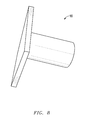
- FIG. 8 illustrates one embodiment of a plug for preventing rotation of the inner flange assembly.
- the present disclosure is directed to an apparatus and method for spooling wire.
- the apparatus is a reel assembly comprising an inner flange assembly and an outer flange assembly.
- the inner flange assembly is supported by the outer flange assembly and capable of freely rotating relative to the outer flange assembly.
- wire can be spooled from the reel assembly while the assembly rests directly on the ground or some other surface.
- a reel assembly 1 is shown.
- the reel assembly 1 comprises two major components—an outer flange assembly 2 and an inner flange assembly 3 .
- the outer flange assembly 2 comprises two outer supporting walls 2 a of substantially equal shape and size connected by a bearing assembly comprising a tube 4 and bearings 5 .
- the outer supporting 2 a walls can be various shapes, including but not limited to circular, quadrilateral, or triangular. In a preferred embodiment, the outer supporting walls 2 a are circular.
- the inner flange assembly 3 also comprises two inner supporting walls 3 a of substantially equal shape and size connected by a spooling seat 6 .
- the inner supporting walls 3 a of the inner flange assembly 3 can also be various shapes, including but not limited to circular, quadrilateral, or triangular. In a preferred embodiment, the inner supporting walls 3 a are circular. Furthermore, in a preferred embodiment, the inner supporting walls 3 a are slightly smaller than the outer supporting walls 2 a . For example the overall dimensions of the inner supporting walls 3 a are less than the outer supporting walls 2 a to allow free spinning of the inner flange assembly 3 relative to the outer flange assembly 2 .
- the distance between the inner supporting walls 3 a is designed to be slightly smaller than the distance between the outer supporting walls 2 a .
- the inner flange assembly 3 is designed to fit within the outer flange assembly 2 between the outer supporting walls 2 a .
- the inner flange assembly 3 further comprises a bore 7 through the center of the inner supporting walls 3 a and spooling seat 6 .
- the bore 7 is designed to receive the tube 4 of the outer flange assembly 2 so that the inner flange assembly 3 is supported by the outer flange assembly 2 .
- the inner flange assembly 3 When assembled, the inner flange assembly 3 is capable of freely rotating about the bearing assembly. As the inner flange assembly 3 rotates the outer flange assembly 2 remains stationary. In this way, wire can be spooled from the reel assembly while the assembly rests on the ground or any other surface.
- the outer supporting walls 2 a are connected via a bearing assembly comprising a tube 4 , bearings 5 , a long bolt 8 and attachment bolts 9 .
- the tube 4 and bearings 5 can be made of any number of materials, including but not limited to steel, plastics or polyacetal.
- the bearings 5 are made of polyacetal, which has low weight and has low coefficients of friction, and the tube 4 is made of steel. Referring to FIGS. 3-6 by way of non-limiting example, and consistent with embodiments of the invention, the bearings 5 are connected to the inner surfaces of the outer supporting walls 2 a .
- any number of means can be used to attach the bearings 5 to the outer supporting walls 2 a , including but not limited to bolts, screws or glues.
- the bearings 5 are fastened to the outer supporting walls 2 a via attachment bolts 9 .
- Each end of the tube 4 is connected to a surface of each of the bearings 5 wherein the tube 4 and bearings 5 are adapted to allow the inner flange assembly 3 to freely rotate.
- the outer supporting walls 2 a are secured to the bearings 5 via a long bolt 8 such that the tube 4 is sandwiched on and between bearings 5 .
- the long bolt passes from one of the outer supporting walls 2 a , through a first bearing 5 , through the tube 4 , through a second bearing 5 , and through a second outer supporting wall 2 a.
- the bearings 5 comprise primarily four stages 10 , 11 , 12 and 13 .
- the first stage 10 is designed to mate with a bore of an outer supporting wall 2 a .
- the second stage 11 includes bolt holes 14 and is designed to secure the bearings 5 to the inner surface of the outer supporting wall 2 a .
- the third stage 12 is designed to maintain a separation between the inner supporting walls 3 a of the inner flange assembly 3 and the outer supporting walls 2 a of the outer flange assembly 2 . In this way, the inner flange assembly 3 is able to freely rotate relative to the outer flange assembly 2 .
- the fourth stage 13 is sized to mate with the tube 4 .
- the outer supporting walls 2 a and inner supporting walls 3 a comprise holes 15 to receive a plug 16 .
- a plug 16 is designed to fit through the outer supporting wall and inner supporting wall holes 15 (see FIGS. 1, 2, 3 ).
- the plug 16 is placed through the holes 15 in both the outer supporting wall 2 a and the inner supporting wall 3 a the inner flange assembly 3 is secured in a locked position to the outer flange assembly 2 and thereby unable to freely rotate.
- wire is spooled from the reel assembly 1 during a wire pulling event.
- the reel assembly 1 comprises an inner flange assembly 3 and an outer flange assembly 2 .
- Wire is wrapped around the inner flange assembly 3 for spooling.
- the inner flange assembly 3 is supported by the outer flange assembly 2 and capable of freely rotating relative to the outer flange assembly 2 .
- Wire is spooled from the reel assembly 1 while the assembly rests directly on the ground or some other surface.
Abstract
A reel apparatus and method comprising an inner flange assembly, an outer flange assembly, and a bearing assembly coupled to the inner and outer flange assemblies. The inner flange assembly is capable of freely rotating relative to the outer flange assembly. In another embodiment, wire is spooled from a reel assembly comprising an inner flange assembly and an outer flange assembly.
Description
The subject application is a continuation of U.S. patent application Ser. No. 13/545,501, filed Jul. 10, 2012 and is incorporated in its entirety by reference.
Not applicable.
Not applicable.
1. Field of the Invention
The present disclosure generally relates to apparatuses and methods for spooling wire, and more particularly, to a compact reel assembly capable of spooling wire independent of a jack stand or other reel support or spooling device.
2. Description of Related Art
To distribute electricity throughout a building, insulated electrical wires or cables are installed between a power source and a power distribution box and routed to electrical boxes to supply electricity to a device. Often, these electrical wires or cables are routed through multiple conduits throughout the building spanning great distances. As such, installing electrical wires presents both logistical and mechanical challenges. Wires are typically installed in a building by pulling the wire via pulling cables through the building's infrastructure. The wire is spooled off of a reel assembly during the wire pulling process.
Wire is typically transported from a wire manufacturing site to the building construction site on the reel assembly. These reel assemblies can have diameters of up to 48 inches or more, and are capable of carrying thousands of pounds of wire. At the construction site, construction workers are faced with the challenge of spooling the large bulk of wire from the reel assembly during a wire pull. The reel assembly is usually lifted off of the ground and set upon a pair of jack stands, which allows the reel to freely spin during a wire pull. During a wire pull, one end of the wire is attached to a pulling cable. Today, electric-powered machines are used to apply a pulling tension to the pulling cable, thereby spooling the wire off of the reel and through the building's infrastructure.
The use of jack stands to support the reel assembly during a wire pull has a number of significant disadvantages. For example, it requires heavy machinery to lift a large reel from the ground to the jack stand platform. This use of heavy machinery is both costly and dangerous to construction workers. Also, jack stands are themselves large pieces of equipment. They are difficult to transport, and when installed, they consume a large amount of floor space at a construction site. For smaller construction sites, the jack stand can present significant space challenges during construction. One solution to the above is to deliver the reel and wire to the construction site on a portable jack stand installed on a flat-bed truck. However, this solution also has many disadvantages. First, the jack stands are large and limit the amount of available flat-bed space to transport multiple reels. Second, flat-bed trucks can take up a large amount of space at a construction site when positioned for spooling. Another solution is to use portable jack stands with built-in lifting mechanisms. However, these jack stands require additional equipment, and again, they can take up an inconvenient amount of space at a construction site.
Thus, there is need in the art for an apparatus and method that eliminates the need to use a jack stand to spool wire from a reel during a wire pull. There is also need in the art for a reel system that is compact, easily transportable, and capable of spooling wire while resting on the ground or some other surface.
The present disclosure is directed to an apparatus for spooling wire. In a preferred embodiment, the apparatus is a reel assembly comprising an inner flange assembly and an outer flange assembly. The inner flange assembly is supported by the outer flange assembly and capable of freely rotating relative to the outer flange assembly.
In another embodiment, a method is disclosed for spooling wire from a reel. The reel assembly comprises an inner flange assembly and an outer flange assembly. Wire is wrapped around the inner flange assembly for spooling. The inner flange assembly is supported by the outer flange assembly and capable of freely rotating relative to the outer flange assembly. Wire is spooled from the reel assembly while the assembly rests directly on the ground or some other surface.
The foregoing summary, as well as the following detailed description, will be better understood when read in conjunction with the appended drawings. For the purpose of illustration, there is shown in the drawings certain embodiments of the present disclosure. It should be understood, however, that the invention is not limited to the precise arrangements and instrumentalities shown.
In the drawings:
Before explaining at least one embodiment of the invention in detail, it is to be understood that the invention is not limited in its application to the details of construction and to the arrangements of the components set forth in the following description or illustrated in the drawings. The invention is capable of other embodiments and of being practiced and carried out in various ways. Also, it is to be understood that the phraseology and terminology employed herein are for the purpose of description and should not be regarded as limiting.
It should be understood that any one of the features of the invention may be used separately or in combination with other features. Other systems, methods, features, and advantages of the present invention will be or become apparent to one with skill in the art upon examination of the drawings and the detailed description. It is intended that all such additional systems, methods, features, and advantages be included within this description, be within the scope of the present invention, and be protected by the accompanying claims.
The present disclosure is described below with reference to the Figures in which various embodiments of the present invention are shown. The subject matter of the disclosure may, however, be embodied in many different forms and should not be construed as limited to the exemplary embodiments set forth herein. It is also understood that the term “wire” is not limiting, and refers to wires, cables, electrical lines, or any other materials that are spooled from a reel.
The present disclosure is directed to an apparatus and method for spooling wire. In a preferred embodiment, the apparatus is a reel assembly comprising an inner flange assembly and an outer flange assembly. The inner flange assembly is supported by the outer flange assembly and capable of freely rotating relative to the outer flange assembly. With this design, wire can be spooled from the reel assembly while the assembly rests directly on the ground or some other surface.
Referring to FIGS. 1A-1E, 2 and 3 by way of non-limiting example, and consistent with embodiments of the invention, a reel assembly 1 is shown. The reel assembly 1 comprises two major components—an outer flange assembly 2 and an inner flange assembly 3. The outer flange assembly 2 comprises two outer supporting walls 2 a of substantially equal shape and size connected by a bearing assembly comprising a tube 4 and bearings 5. The outer supporting 2 a walls can be various shapes, including but not limited to circular, quadrilateral, or triangular. In a preferred embodiment, the outer supporting walls 2 a are circular.
The inner flange assembly 3 also comprises two inner supporting walls 3 a of substantially equal shape and size connected by a spooling seat 6. The inner supporting walls 3 a of the inner flange assembly 3 can also be various shapes, including but not limited to circular, quadrilateral, or triangular. In a preferred embodiment, the inner supporting walls 3 a are circular. Furthermore, in a preferred embodiment, the inner supporting walls 3 a are slightly smaller than the outer supporting walls 2 a. For example the overall dimensions of the inner supporting walls 3 a are less than the outer supporting walls 2 a to allow free spinning of the inner flange assembly 3 relative to the outer flange assembly 2. The distance between the inner supporting walls 3 a is designed to be slightly smaller than the distance between the outer supporting walls 2 a. As such, the inner flange assembly 3 is designed to fit within the outer flange assembly 2 between the outer supporting walls 2 a. The inner flange assembly 3 further comprises a bore 7 through the center of the inner supporting walls 3 a and spooling seat 6. The bore 7 is designed to receive the tube 4 of the outer flange assembly 2 so that the inner flange assembly 3 is supported by the outer flange assembly 2.
When assembled, the inner flange assembly 3 is capable of freely rotating about the bearing assembly. As the inner flange assembly 3 rotates the outer flange assembly 2 remains stationary. In this way, wire can be spooled from the reel assembly while the assembly rests on the ground or any other surface.
The outer supporting walls 2 a are connected via a bearing assembly comprising a tube 4, bearings 5, a long bolt 8 and attachment bolts 9. The tube 4 and bearings 5 can be made of any number of materials, including but not limited to steel, plastics or polyacetal. In a preferred embodiment, the bearings 5 are made of polyacetal, which has low weight and has low coefficients of friction, and the tube 4 is made of steel. Referring to FIGS. 3-6 by way of non-limiting example, and consistent with embodiments of the invention, the bearings 5 are connected to the inner surfaces of the outer supporting walls 2 a. It is understood by a person of ordinary skill in the art that any number of means can be used to attach the bearings 5 to the outer supporting walls 2 a, including but not limited to bolts, screws or glues. In a preferred embodiment the bearings 5 are fastened to the outer supporting walls 2 a via attachment bolts 9. Each end of the tube 4 is connected to a surface of each of the bearings 5 wherein the tube 4 and bearings 5 are adapted to allow the inner flange assembly 3 to freely rotate. The outer supporting walls 2 a are secured to the bearings 5 via a long bolt 8 such that the tube 4 is sandwiched on and between bearings 5. The long bolt passes from one of the outer supporting walls 2 a, through a first bearing 5, through the tube 4, through a second bearing 5, and through a second outer supporting wall 2 a.
A preferred embodiment of the bearings 5 is depicted in FIG. 7 . The bearings 5 comprise primarily four stages 10, 11, 12 and 13. The first stage 10 is designed to mate with a bore of an outer supporting wall 2 a. The second stage 11 includes bolt holes 14 and is designed to secure the bearings 5 to the inner surface of the outer supporting wall 2 a. The third stage 12 is designed to maintain a separation between the inner supporting walls 3 a of the inner flange assembly 3 and the outer supporting walls 2 a of the outer flange assembly 2. In this way, the inner flange assembly 3 is able to freely rotate relative to the outer flange assembly 2. Finally, the fourth stage 13 is sized to mate with the tube 4.
In an alternative embodiment, the outer supporting walls 2 a and inner supporting walls 3 a comprise holes 15 to receive a plug 16. As shown in FIG. 8 , a plug 16 is designed to fit through the outer supporting wall and inner supporting wall holes 15 (see FIGS. 1, 2, 3 ). When the plug 16 is placed through the holes 15 in both the outer supporting wall 2 a and the inner supporting wall 3 a the inner flange assembly 3 is secured in a locked position to the outer flange assembly 2 and thereby unable to freely rotate.
In another embodiment of the invention, wire is spooled from the reel assembly 1 during a wire pulling event. The reel assembly 1 comprises an inner flange assembly 3 and an outer flange assembly 2. Wire is wrapped around the inner flange assembly 3 for spooling. The inner flange assembly 3 is supported by the outer flange assembly 2 and capable of freely rotating relative to the outer flange assembly 2. Wire is spooled from the reel assembly 1 while the assembly rests directly on the ground or some other surface.
One skilled in the art will recognize that different embodiments may be formed in a similar manner having different characteristics depending upon need, performance, or some other criteria. It will thus be appreciated by those skilled in the art that changes could be made to the embodiments described above without departing from the broad inventive concept thereof. It is understood, therefore, that the invention disclosed herein is not limited to the particular embodiments disclosed, but it is intended to cover modifications within the spirit and scope of the present invention as defined by the appended claims.
Claims (20)
1. A reel apparatus comprising:
an inner flange assembly, wherein the inner flange assembly has a first end and a second end;
an outer flange assembly, wherein the outer flange assembly has a first end and a second end;
a locking device removably connected to only one of the first ends or the second ends of the inner and outer flange assemblies;
a bearing assembly coupled to the inner and outer flange assemblies; and
wherein the inner flange assembly is capable of freely rotating relative to the outer flange assembly when the locking device is not connected to either the first ends or second ends of the inner and outer flange assemblies.
2. The apparatus of claim 1 , wherein the bearing assembly is connected to the outer flange assembly.
3. The apparatus of claim 2 , wherein the bearing assembly is bolted to the outer flange assembly.
4. The apparatus of claim 2 , wherein the bearing assembly comprises a stage, the stage is positioned between the inner flange assembly and the outer flange assembly and maintains a separation between the inner flange assembly and the outer flange assembly.
5. The apparatus of claim 4 , wherein the outer flange assembly comprises a first outer wall and a second outer wall, the first and second outer walls coupled to a first tube.
6. The apparatus of claim 5 , wherein the inner flange assembly comprises a first inner wall and a second inner wall, the first and second inner walls coupled to a second tube.
7. The apparatus of claim 6 , wherein the inner flange assembly tube is freely rotatable around the outer flange assembly tube.
8. The apparatus of claim 6 , wherein the first and second inner walls have an inner wall diameter, wherein the first and second outer walls have an outer wall diameter, and wherein the inner wall diameter is less than the outer wall diameter.
9. The apparatus of claim 6 , wherein the first and second outer walls or first and second inner walls are any combination of circular, quadrilateral or triangular.
10. The apparatus of claim 1 , wherein the inner flange assembly width is less than the outer flange assembly width.
11. A method of spooling wire, comprising:
spooling wire from a reel assembly; and
wherein the reel assembly comprises an inner flange assembly, wherein the inner flange assembly has a first end and a second end, an outer flange assembly, wherein the outer flange assembly has a first end and a second end, a locking device removably connected to only one of the first ends or the second ends of the inner and outer flange assemblies, a bearing assembly coupled to the inner and outer flange assemblies, and wherein the inner flange assembly is capable of freely rotating relative to the outer flange assembly when the locking device is not connected to either the first ends or second ends of the inner and outer flange assemblies.
12. The method of claim 11 , wherein the outer flange assembly comprises two outer supporting walls.
13. The method of claim 12 , wherein the inner flange assembly comprises two inner supporting walls.
14. The method of claim 13 , wherein the bearing assembly comprises a stage.
15. The method of claim 14 , wherein the stage is positioned between the inner supporting walls and the adjacent outer supporting walls and maintains a separation between the inner supporting walls and the outer supporting walls.
16. The method of claim 13 , wherein the outer flange assembly comprises a tube coupled to the outer supporting walls.
17. The method of claim 16 , wherein the inner flange assembly rotates about the tube of the outer flange assembly.
18. The method of claim 16 , wherein the outer supporting walls and the bearing assembly are fixed together by a long bolt.
19. The method of claim 13 , wherein the outer supporting walls or inner supporting walls are any combination of circular, quadrilateral or triangular.
20. The method of claim 11 , wherein the bearing assembly is made of one or more of steel, plastic or polyacetal.
Priority Applications (7)
| Application Number | Priority Date | Filing Date | Title |
|---|---|---|---|
| US14/659,165 US9738485B1 (en) | 2012-07-10 | 2015-03-16 | Apparatus and method for spooling wire |
| US14/837,813 US9815658B1 (en) | 2012-07-10 | 2015-08-27 | Apparatus and method for spooling wire |
| US15/134,254 US9676587B1 (en) | 2012-07-10 | 2016-04-20 | Apparatus and method for spooling wire |
| US15/594,299 US10421636B1 (en) | 2012-07-10 | 2017-05-12 | Apparatus and method for spooling wire |
| US16/016,645 US10625975B1 (en) | 2012-07-10 | 2018-06-24 | Apparatus and method for spooling wire |
| US16/822,940 US11186461B1 (en) | 2012-07-10 | 2020-03-18 | Apparatus and method for spooling wire |
| US16/863,878 US11339024B1 (en) | 2012-07-10 | 2020-04-30 | Ground wire side car |
Applications Claiming Priority (2)
| Application Number | Priority Date | Filing Date | Title |
|---|---|---|---|
| US13/545,501 US9004392B1 (en) | 2012-07-10 | 2012-07-10 | Apparatus and method for spooling wire |
| US14/659,165 US9738485B1 (en) | 2012-07-10 | 2015-03-16 | Apparatus and method for spooling wire |
Related Parent Applications (3)
| Application Number | Title | Priority Date | Filing Date |
|---|---|---|---|
| US13/545,501 Continuation US9004392B1 (en) | 2012-07-10 | 2012-07-10 | Apparatus and method for spooling wire |
| US14/072,539 Continuation-In-Part US9452908B1 (en) | 2012-07-10 | 2013-11-05 | Apparatus and method for a free-spinning wire dispensing reel |
| US15/134,254 Continuation US9676587B1 (en) | 2012-07-10 | 2016-04-20 | Apparatus and method for spooling wire |
Related Child Applications (3)
| Application Number | Title | Priority Date | Filing Date |
|---|---|---|---|
| US14/072,539 Continuation-In-Part US9452908B1 (en) | 2012-07-10 | 2013-11-05 | Apparatus and method for a free-spinning wire dispensing reel |
| US14/837,813 Continuation US9815658B1 (en) | 2012-07-10 | 2015-08-27 | Apparatus and method for spooling wire |
| US15/134,254 Continuation-In-Part US9676587B1 (en) | 2012-07-10 | 2016-04-20 | Apparatus and method for spooling wire |
Publications (1)
| Publication Number | Publication Date |
|---|---|
| US9738485B1 true US9738485B1 (en) | 2017-08-22 |
Family
ID=52782107
Family Applications (3)
| Application Number | Title | Priority Date | Filing Date |
|---|---|---|---|
| US13/545,501 Active 2033-06-06 US9004392B1 (en) | 2012-07-10 | 2012-07-10 | Apparatus and method for spooling wire |
| US14/659,165 Active 2032-10-25 US9738485B1 (en) | 2012-07-10 | 2015-03-16 | Apparatus and method for spooling wire |
| US14/837,813 Active US9815658B1 (en) | 2012-07-10 | 2015-08-27 | Apparatus and method for spooling wire |
Family Applications Before (1)
| Application Number | Title | Priority Date | Filing Date |
|---|---|---|---|
| US13/545,501 Active 2033-06-06 US9004392B1 (en) | 2012-07-10 | 2012-07-10 | Apparatus and method for spooling wire |
Family Applications After (1)
| Application Number | Title | Priority Date | Filing Date |
|---|---|---|---|
| US14/837,813 Active US9815658B1 (en) | 2012-07-10 | 2015-08-27 | Apparatus and method for spooling wire |
Country Status (1)
| Country | Link |
|---|---|
| US (3) | US9004392B1 (en) |
Cited By (2)
| Publication number | Priority date | Publication date | Assignee | Title |
|---|---|---|---|---|
| US10000356B1 (en) * | 2012-11-05 | 2018-06-19 | Encore Wire Corporation | Apparatus and method for a free-spinning wire dispensing reel |
| US11479439B2 (en) * | 2020-08-11 | 2022-10-25 | Anderson Travis Holdings, LLC | Unidirectional locking spool |
Families Citing this family (21)
| Publication number | Priority date | Publication date | Assignee | Title |
|---|---|---|---|---|
| USD817893S1 (en) | 2016-06-23 | 2018-05-15 | Southwire Company, Llc | Flange with hook aperture |
| USD815049S1 (en) | 2016-06-23 | 2018-04-10 | Southwire Company, Llc | Flange with vertical slot and jack |
| US9403659B2 (en) | 2013-03-05 | 2016-08-02 | Southwire Company, Llc | Rotatable cable reel |
| US9617112B1 (en) * | 2009-10-23 | 2017-04-11 | Southwire Company, Llc | Independently rotatable flanges and attachable arbor hole adapters |
| US9676587B1 (en) * | 2012-07-10 | 2017-06-13 | Encore Wire Corporation | Apparatus and method for spooling wire |
| US9004392B1 (en) * | 2012-07-10 | 2015-04-14 | Encore Wire Corporation | Apparatus and method for spooling wire |
| US10766735B2 (en) | 2015-08-19 | 2020-09-08 | Southwire Company, Llc | Flange stand and adapter for flanges |
| US10023425B2 (en) | 2015-09-17 | 2018-07-17 | Cerro Wire Llc | Device and system to store, maneuver and pay-out material stored on reels |
| USD818440S1 (en) | 2016-06-23 | 2018-05-22 | Southwire Company, Llc | Flange with kidney aperture |
| US9889871B1 (en) | 2016-08-19 | 2018-02-13 | Itool Equipment Holding Llc | Ring apparatus and method for lifting an item for holding windable material |
| US10273111B2 (en) | 2016-12-20 | 2019-04-30 | Sonoco Development, Inc. | Devices for lifting, maneuvering, winding and unwinding reels |
| KR20180077704A (en) * | 2016-12-29 | 2018-07-09 | 엘에스전선 주식회사 | Cable Bobin Assembly |
| KR20180077709A (en) * | 2016-12-29 | 2018-07-09 | 엘에스전선 주식회사 | Cable Bobin Assembly |
| US10954097B2 (en) | 2017-08-16 | 2021-03-23 | Southwire Company, Llc | Reel chock |
| CN107673127A (en) * | 2017-08-18 | 2018-02-09 | 徐州领君仁驰自动化设备有限公司 | Full-automatic unwrapping wire wire stripping take-up coiling binding machine |
| KR20190029947A (en) * | 2017-09-13 | 2019-03-21 | 엘에스전선 주식회사 | Cable Bobin Assembly And Cable Package |
| CN107934702B (en) * | 2017-11-17 | 2020-03-17 | 国网山东省电力公司淄博供电公司 | Retractable grounding wire device |
| US20220135359A1 (en) * | 2019-02-22 | 2022-05-05 | Sealed Air Corporation (Us) | Tension-inducing shaft assemblies |
| CN110203770B (en) * | 2019-07-02 | 2020-09-08 | 惠安县创达智能科技有限公司 | Cable drum winder |
| CN111807160B (en) * | 2020-07-22 | 2022-01-14 | 佛山市科豪制辊有限公司 | Textile machinery winding roller with speed measuring unit separately arranged |
| US11867321B1 (en) | 2021-10-21 | 2024-01-09 | Samuel Combs | Dispensing device and method of using same |
Citations (13)
| Publication number | Priority date | Publication date | Assignee | Title |
|---|---|---|---|---|
| US709932A (en) | 1901-12-26 | 1902-09-30 | Bert L Hiatt | Wire-reel truck. |
| US970884A (en) | 1910-01-11 | 1910-09-20 | Harold Boothby Carter | Reel-cradle. |
| GB353684A (en) | 1930-07-19 | 1931-07-30 | Thomas Owen Bowen | Improvements in or relating to hose reels |
| US3152772A (en) | 1960-12-31 | 1964-10-13 | Bjphirn E Schjerven | Transporting devices |
| US3652026A (en) | 1969-11-04 | 1972-03-28 | Folke Hildemar Awebro | Device for supporting and transporting a cable drum |
| US3976260A (en) | 1975-02-07 | 1976-08-24 | Grantham & Oleson, Inc. | Transportable cable reel |
| US4784221A (en) | 1987-05-27 | 1988-11-15 | Share Jack H | Wellpoint system and reel |
| US20100230528A1 (en) | 2009-03-12 | 2010-09-16 | Byron Singleton | Spool holder and support system |
| US20110095124A1 (en) | 2009-10-23 | 2011-04-28 | Andrea Timothy M | Parallel Conductor Spool With Multiple Independent Bays |
| US8025261B2 (en) | 2007-09-11 | 2011-09-27 | Southwire Company | Combination stand and jack for wire spools |
| US8444078B1 (en) | 2005-12-23 | 2013-05-21 | The United States Of America As Represented By The Secretary Of The Navy | Cable reel |
| US9004392B1 (en) * | 2012-07-10 | 2015-04-14 | Encore Wire Corporation | Apparatus and method for spooling wire |
| US20150321876A1 (en) | 2013-03-05 | 2015-11-12 | Southwire Company | Rotatable Cable Reel |
-
2012
- 2012-07-10 US US13/545,501 patent/US9004392B1/en active Active
-
2015
- 2015-03-16 US US14/659,165 patent/US9738485B1/en active Active
- 2015-08-27 US US14/837,813 patent/US9815658B1/en active Active
Patent Citations (14)
| Publication number | Priority date | Publication date | Assignee | Title |
|---|---|---|---|---|
| US709932A (en) | 1901-12-26 | 1902-09-30 | Bert L Hiatt | Wire-reel truck. |
| US970884A (en) | 1910-01-11 | 1910-09-20 | Harold Boothby Carter | Reel-cradle. |
| GB353684A (en) | 1930-07-19 | 1931-07-30 | Thomas Owen Bowen | Improvements in or relating to hose reels |
| US3152772A (en) | 1960-12-31 | 1964-10-13 | Bjphirn E Schjerven | Transporting devices |
| US3652026A (en) | 1969-11-04 | 1972-03-28 | Folke Hildemar Awebro | Device for supporting and transporting a cable drum |
| US3976260A (en) | 1975-02-07 | 1976-08-24 | Grantham & Oleson, Inc. | Transportable cable reel |
| US4784221A (en) | 1987-05-27 | 1988-11-15 | Share Jack H | Wellpoint system and reel |
| US8444078B1 (en) | 2005-12-23 | 2013-05-21 | The United States Of America As Represented By The Secretary Of The Navy | Cable reel |
| US8025261B2 (en) | 2007-09-11 | 2011-09-27 | Southwire Company | Combination stand and jack for wire spools |
| US20100230528A1 (en) | 2009-03-12 | 2010-09-16 | Byron Singleton | Spool holder and support system |
| US20110095124A1 (en) | 2009-10-23 | 2011-04-28 | Andrea Timothy M | Parallel Conductor Spool With Multiple Independent Bays |
| US8245965B2 (en) | 2009-10-23 | 2012-08-21 | Southwire Company | Parallel conductor spool with multiple independent bays |
| US9004392B1 (en) * | 2012-07-10 | 2015-04-14 | Encore Wire Corporation | Apparatus and method for spooling wire |
| US20150321876A1 (en) | 2013-03-05 | 2015-11-12 | Southwire Company | Rotatable Cable Reel |
Non-Patent Citations (1)
| Title |
|---|
| CarrisReels, "10-inch Caddies for in-the-box packaging reels from Carris Reels", Carris Reeels, Inc. 2008, http://carris.com/products/caddy10.html (Printed from website Oct. 11, 2012). |
Cited By (2)
| Publication number | Priority date | Publication date | Assignee | Title |
|---|---|---|---|---|
| US10000356B1 (en) * | 2012-11-05 | 2018-06-19 | Encore Wire Corporation | Apparatus and method for a free-spinning wire dispensing reel |
| US11479439B2 (en) * | 2020-08-11 | 2022-10-25 | Anderson Travis Holdings, LLC | Unidirectional locking spool |
Also Published As
| Publication number | Publication date |
|---|---|
| US9815658B1 (en) | 2017-11-14 |
| US9004392B1 (en) | 2015-04-14 |
Similar Documents
| Publication | Publication Date | Title |
|---|---|---|
| US9738485B1 (en) | Apparatus and method for spooling wire | |
| US11912527B1 (en) | Apparatus and method for a free-spinning wire dispensing reel | |
| US20230406668A1 (en) | Rotatable Cable Reel | |
| US9079745B2 (en) | Pay-off assembly | |
| US11186461B1 (en) | Apparatus and method for spooling wire | |
| US9676587B1 (en) | Apparatus and method for spooling wire | |
| US20180229983A1 (en) | Winch Assembly and Method of Use | |
| US11772930B1 (en) | Apparatus and method for spooling wire | |
| US20030089818A1 (en) | A reel for paying out elongate elements for interior cabling of buildings | |
| US11339024B1 (en) | Ground wire side car | |
| JP3487590B2 (en) | Transportation equipment | |
| US11691843B1 (en) | Ground wire side car | |
| GB2554873A (en) | A mobile support for use in a utility service installation system and method | |
| KR102471170B1 (en) | Electric cable installation and electric cable recovery device | |
| AU2019201257B9 (en) | Rotatable cable reel | |
| US2179825A (en) | Wire reel support, rack, or stand | |
| US20190322479A1 (en) | A system and a method for handling, storing and transportation | |
| JP7403766B2 (en) | Frame device and wire material drawing device | |
| US20220212891A1 (en) | Rotatable Cable Reel | |
| KR102396576B1 (en) | Cable Winding Device For Cable | |
| CN215340477U (en) | Optical cable emergency communication support | |
| US20240140757A1 (en) | Rotatable Cable Reel | |
| CN113911820A (en) | Power cable pay-off device | |
| JP2869634B2 (en) | Method and apparatus for winding large wall curtain film | |
| KR20230001313U (en) | Electric cable installation and electric cable recovery device |
Legal Events
| Date | Code | Title | Description |
|---|---|---|---|
| AS | Assignment |
Owner name: ENCORE WIRE CORPORATION, TEXAS Free format text: ASSIGNMENT OF ASSIGNORS INTEREST;ASSIGNORS:BIGBEE, WILLIAM T., JR.;RHOADS, JOHN L.;REEL/FRAME:035196/0551 Effective date: 20120709 |
|
| STCF | Information on status: patent grant |
Free format text: PATENTED CASE |
|
| MAFP | Maintenance fee payment |
Free format text: PAYMENT OF MAINTENANCE FEE, 4TH YEAR, LARGE ENTITY (ORIGINAL EVENT CODE: M1551); ENTITY STATUS OF PATENT OWNER: LARGE ENTITY Year of fee payment: 4 |