US9730689B2 - Rotational action needle driver - Google Patents
Rotational action needle driver Download PDFInfo
- Publication number
- US9730689B2 US9730689B2 US14/949,877 US201514949877A US9730689B2 US 9730689 B2 US9730689 B2 US 9730689B2 US 201514949877 A US201514949877 A US 201514949877A US 9730689 B2 US9730689 B2 US 9730689B2
- Authority
- US
- United States
- Prior art keywords
- rotational
- bar
- distal end
- actuator
- suturing
- Prior art date
- Legal status (The legal status is an assumption and is not a legal conclusion. Google has not performed a legal analysis and makes no representation as to the accuracy of the status listed.)
- Active
Links
Images


Classifications
-
- A—HUMAN NECESSITIES
- A61—MEDICAL OR VETERINARY SCIENCE; HYGIENE
- A61B—DIAGNOSIS; SURGERY; IDENTIFICATION
- A61B17/00—Surgical instruments, devices or methods
- A61B17/04—Surgical instruments, devices or methods for suturing wounds; Holders or packages for needles or suture materials
- A61B17/06—Needles ; Sutures; Needle-suture combinations; Holders or packages for needles or suture materials
- A61B17/062—Needle manipulators
-
- A—HUMAN NECESSITIES
- A61—MEDICAL OR VETERINARY SCIENCE; HYGIENE
- A61B—DIAGNOSIS; SURGERY; IDENTIFICATION
- A61B17/00—Surgical instruments, devices or methods
- A61B17/04—Surgical instruments, devices or methods for suturing wounds; Holders or packages for needles or suture materials
- A61B17/0491—Sewing machines for surgery
-
- A—HUMAN NECESSITIES
- A61—MEDICAL OR VETERINARY SCIENCE; HYGIENE
- A61B—DIAGNOSIS; SURGERY; IDENTIFICATION
- A61B17/00—Surgical instruments, devices or methods
- A61B2017/0042—Surgical instruments, devices or methods with special provisions for gripping
-
- A—HUMAN NECESSITIES
- A61—MEDICAL OR VETERINARY SCIENCE; HYGIENE
- A61B—DIAGNOSIS; SURGERY; IDENTIFICATION
- A61B17/00—Surgical instruments, devices or methods
- A61B17/28—Surgical forceps
- A61B17/2812—Surgical forceps with a single pivotal connection
- A61B17/2833—Locking means
- A61B2017/2837—Locking means with a locking ratchet
-
- A—HUMAN NECESSITIES
- A61—MEDICAL OR VETERINARY SCIENCE; HYGIENE
- A61B—DIAGNOSIS; SURGERY; IDENTIFICATION
- A61B17/00—Surgical instruments, devices or methods
- A61B17/28—Surgical forceps
- A61B17/29—Forceps for use in minimally invasive surgery
- A61B2017/2926—Details of heads or jaws
- A61B2017/2927—Details of heads or jaws the angular position of the head being adjustable with respect to the shaft
- A61B2017/2929—Details of heads or jaws the angular position of the head being adjustable with respect to the shaft with a head rotatable about the longitudinal axis of the shaft
-
- A—HUMAN NECESSITIES
- A61—MEDICAL OR VETERINARY SCIENCE; HYGIENE
- A61B—DIAGNOSIS; SURGERY; IDENTIFICATION
- A61B17/00—Surgical instruments, devices or methods
- A61B17/28—Surgical forceps
- A61B17/29—Forceps for use in minimally invasive surgery
- A61B2017/2946—Locking means
-
- A—HUMAN NECESSITIES
- A61—MEDICAL OR VETERINARY SCIENCE; HYGIENE
- A61B—DIAGNOSIS; SURGERY; IDENTIFICATION
- A61B90/00—Instruments, implements or accessories specially adapted for surgery or diagnosis and not covered by any of the groups A61B1/00 - A61B50/00, e.g. for luxation treatment or for protecting wound edges
- A61B90/06—Measuring instruments not otherwise provided for
- A61B2090/067—Measuring instruments not otherwise provided for for measuring angles
Definitions
- the present invention relates generally to a surgical suturing device, more specifically, to an ergonomic rotational action needle driver which enhance the tissue suturing procedure, particularly the one performed on restricted, deep and less accessible locations.
- the instruments used in suturing procedures are the suturing material, the suturing needle and the suturing driver. Efforts made to reduce the suturing time and to enhance the suturing procedures' safety have been focused on performing needle driver's modifications.
- One of the generally unattended deficiencies of the available needle drivers is the handedness of its designs. Some of the deficiencies were attended by U.S. patent application Ser. No. 12/554,795 filed on Sep. 4, 2009 now U.S. Pat. No. 9,192,376. The entire content of U.S. Pat. No. 9,192,376 are hereby incorporated by reference.
- the present invention provides a more efficient simple mechanism as a rotational action needle driver.
- the disclosed embodiment of the present invention helps provide an effective suturing device that enhances the maneuvering and safety of suturing procedures.
- the disclosed invention consists of a suturing needle driver that comprises an ergonomical handle that eases the suturing process. It also comprises a rotational mechanism that permits users to maintain the needle tightly fixed to the needle driver in order to have a best control over the needle and the movements related to the suturing process. It permits the user to position the suturing needle at the exact angle at which the suturing material has to be inserted into the tissue.
- the object of the present invention is to provide a surgical device that eases the suturing procedure associated with deep, restricted areas.
- Another object of the present invention is to provide a surgical suturing needle driver that permits to grasp, secure and rotate a curved surgical needle without requiring a rotational motion at the surgeon's wrist.
- FIG. 1 shows a perspective view of the exemplary embodiment in accordance according with the principles of the present disclosure.
- FIGS. 2A and 2B shows perspective views of the exemplary embodiment with actuator at a first position in accordance according with the principles of the present disclosure.
- FIGS. 3A and 3B shows perspective views of the exemplary embodiment with actuator at second position in accordance according with the principles of the present disclosure.
- FIGS. 4A and 4B shows side views of the exemplary embodiment in accordance according with the principles of the present disclosure.
- FIG. 5 shows a perspective view of the exemplary embodiment in accordance according with the principles of the present disclosure.
- FIG. 6 shows a front view of the exemplary embodiment with actuator at second position in accordance according with the principles of the present disclosure.
- FIG. 7 shows a front view of the exemplary embodiment with actuator at a first position in accordance according with the principles of the present disclosure.
- FIG. 8 shows a top view of the exemplary embodiment with actuator at a first position in accordance according with the principles of the present disclosure.
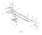
- FIG. 9 shows a bottom view of the exemplary embodiment with actuator at a first position in accordance according with the principles of the present disclosure.
- FIG. 10 shows an exploded view of the exemplary embodiment in accordance according with the principles of the present disclosure.
- FIGS. 11A and 11B shows a detailed view of the exemplary embodiment of locking mechanism in accordance according with the principles of the present disclosure.
- FIG. 1 shows the device 1 of the present disclosure comprises a first elongated element 2 , a second elongated element 3 , an actuator 4 and rotational transfer element 6 and at least an elastic member 7 .
- the first elongated element 3 includes a first elongated body 33 , a first tip 61 at a distal end and a round contour including a first socket 30 at the proximal end.
- the second elongated element 2 includes a second elongated body 23 , a second tip 62 at a distal end and a round contour including a second socket 20 at the proximal end.
- the rounded contour of the first elongated element 3 and second elongated element 2 are ergonomically designed to rest against surgeon's palm his hand, permitting its proper use to right and left handed surgeons, therefore a resting palm wall 21 is provided coupled to the first socket 20 at the proximal end. The surgeon will maintain the handle fixed to the palm his hand by using his thumb.
- the present device comprises several features presented from FIG. 1 through FIG. 11B .
- an object of the present disclosure is to perform safest and simplest suturing procedures.
- the present suturing device 1 comprises a suturing mechanism including an actuator 4 , wherein said actuator 4 initiates the rotational mechanism during the suturing procedure using the present device 1 .
- the actuator 4 is mechanically coupled to the first elongated element 3 at a first pivot point, as shown in 2 A through 3 B.
- the actuator 4 is mechanically coupled to the first elongated body 33 by a pin 8 , wherein said pin 8 permits rotational movement or displacement of said actuator 4 with respects to said first pivot point.
- the actuator 4 comprises a platform 4 A, mainly extended away from the first elongated body 33 , configured or shaped to receive a thumb and be driven by said thumb, Base on the present exemplary embodiment the actuator is driven by the thumb, wherein said thumb pushes said platform 4 A towards the first elongated body 33 moving the actuator from a first position, as shown in FIGS.
- the actuator 4 comprises a linear actuator mechanism fixed to said platform 4 A, wherein said linear actuator comprises a rack 51 , which moves mainly vertical toward the first elongated body 33 .
- the rack 51 is configured or designed to interact with the rotational bar 6 , more particularly with the pinion 600 at a distal end of said rotational bar 6 , as shown in FIG. 2A through 3B .
- the interaction of the rack and pinion converts the radial displacement of the actuator 4 into a rotational movement of the rotational bar 6 .
- the rotational bar 6 structures is explained in more details below.
- FIG. 4A is directed to show the displacement of the actuator with respects to the pin 8 .
- the pin 8 comprises a length longer than the actuator length X 2 with respect to the pin 8 .
- the pin comprises a total length X 3
- the actuator comprises an attachment portion 71 connected to the pin 8 comprising a second length X 2 .
- the difference between the lengths provides a space X 1 for the displacement of the attachment portion 71 .
- the displacement of said attachment portion 71 is enough to move the rack 51 from providing a rotational direction of the pinion to another direction (i.e. from counterclockwise to clockwise).
- the space X′ 1 provided on FIG.
- FIG. 2A is positioned at a portion of the pin 8 different from the one showed in FIG. 4A .
- the position of the rack 51 in FIG. 2A will provide clockwise motion of the pinion 600 and counterclockwise motion of the pinion 600 in FIG. 4A . It is important to understand that the movement of the actuator 4 , more particularly the displacement of the attachment portion 71 is accomplish when the actuator is in the first position.
- the actuator 4 further comprises an elastic or resilient member 7 coupled to the platform 4 a .
- the elastic member 7 is configured to be compress from the first position to the second position. Subsequently as soon the platform 4 a is release returns to its original position or first position.
- the elastic member 7 in the exemplary embodiment is a spring configured to recoil the platform to the first position. It is important to understand that any other resilient member can be used as long assists to recoil the platform 4 a.
- the first elongated body 33 extends from said first socket 30 towards said first tip 61 .
- the first elongated body 33 comprises at least a set of walls 331 , 332 forming a clearance between each other, as shown in FIG. 4A .
- the clearance between the walls is enough to provide space for the rotational bar 6 and a portion of the second elongated body 23 to be located between them while the suturing device 1 is in use.
- the suturing device is considered in use when the tips 61 , 62 are grasping the needle N or in close contact.
- the second elongated element 2 includes a second elongated body 23 , a second tip 62 at a distal end and a round contour including a second socket 20 at the proximal end.
- the elongated body 23 comprises a rotational bar support S.
- the rotational bar support S hold the rotational bar 6 in position with respect to the second elongated body 23 while provide bearing for the rotational movement of said rotational bar 6 when the actuator 4 interacts with the pinion 600 .
- the rotational bar is mechanical coupled to the second tip 62 , Therefore the rotational movement generated at the pinion is transferred to the second tip 62 .
- the first elongated element 2 and the second elongated member 3 are joint together at the box joint P.
- the box joint P serves as an intersection or pivot point between the first elongated element 3 and the second elongated element 2 .
- the second tip 62 and first tip 61 extends away from the box joint P.
- FIG. 5 through FIG. 9 shows the grasping portion created by first tip 61 and second tip 62 .
- the grasping force is preferred to be in an oblique manner, however the contact between tips 61 , 62 maybe provided in other angles.
- Each tip 61 , 62 is removable and comprises at least a distal end gear 60 .
- the gear is intended to assists to transmit the rotational movement of the second tip 62 connected to the rotational bar 6 to the first tip during the suturing procedures. It is important to understand that the gear serves as a rotation transmitting element for assisting to transferring the rotational motion from second tip 62 to the first tip 61 , therefore any other rotation transmitting element could be used.
- each tip 62 , 62 comprises at least contact distal end 620 , 621 including grooves.
- the grooves or recess assists the increases the grasping force at the contact distal end 620 , 621 .
- the recess area may vary in order to assists to grasp different sizes of needles N.
- the tip 61 , 62 may vary in length.
- the tip 61 , 62 are made of any selected material capable to perform at least the functions herein mentioned. The selection of the material depends on the field the device is going to be employed.
- the contact distal end 620 , 621 is preferred to have a surface that assist the performed action.
- the tips may include a layer of antibiotic or any other medical substance that assist the suturing and healing process of the patient.
- the tips are removable and securely installed at the distal end of said elongated elements 2 , 3 . It is important to understand that the tips 61 , 62 are removable and/or replaceable due to the need of grooves sizes for specific needles N or/and due to wear and tear problems, such as losing grasping force and/or avoiding particles losses due to friction.
- a locking mechanism 200 is located between the first elongated body 33 and second elongated body 23 , as shown in FIGS. 11A and 11B .
- Each elongated body comprises a extended member with teeth interlocking with each other, in the form of a ratchet, assisting to hold the position between elongated bodies and consequently the distance between the first tips 62 and second tip 61 .
- Further from said extended member 200 201 comprise protrusion 22 a , 22 b . It is important to understand that the current device is usually on an open stage wherein the locking mechanism is not providing a constant distance between the first elongated element 3 and said second elongated element 2 . While using the device 1 the user desires to close the gap between the elongated elements 2 , 3 in order to provide a constant distance between these two parts, consequently the first tip 62 and second tip 61 are in close contact grasping the needle N.
- the actuator 4 comprises a linear actuator including rack 51 and a flange 50 .
- the flange 50 comprises at least two bumps 50 a , 50 b .
- the bump 50 a , 50 b are intended to assists with the unlocking mechanism by pushing up protrusions 22 b , 22 a .
- the protrusion 22 b , 22 a extends from the locking mechanism 200 , 201 .
- the bumps 50 a , 50 b are preferably located closer to the platform 4 a .
- the purpose of providing the bumps 50 a , 50 b closer to the platform is to provide enough displacement of the rack 51 to rotate the pinion 600 before the bumps 50 a , 50 b interacts with the protrusions 22 a , 22 b . Therefore, when the actuator 4 is close to the second position the bumps 50 a , 50 b push up the protrusion 22 a , 22 b unlocking the rackets or locking mechanism 200 , 201 .
Landscapes
- Health & Medical Sciences (AREA)
- Life Sciences & Earth Sciences (AREA)
- Surgery (AREA)
- Heart & Thoracic Surgery (AREA)
- Engineering & Computer Science (AREA)
- Biomedical Technology (AREA)
- Nuclear Medicine, Radiotherapy & Molecular Imaging (AREA)
- Medical Informatics (AREA)
- Molecular Biology (AREA)
- Animal Behavior & Ethology (AREA)
- General Health & Medical Sciences (AREA)
- Public Health (AREA)
- Veterinary Medicine (AREA)
- Surgical Instruments (AREA)
Abstract
Description
Claims (5)
Priority Applications (2)
| Application Number | Priority Date | Filing Date | Title |
|---|---|---|---|
| US14/949,877 US9730689B2 (en) | 2009-09-04 | 2015-11-23 | Rotational action needle driver |
| PCT/US2016/063513 WO2017091680A1 (en) | 2015-11-23 | 2016-11-23 | Rotational action needle driver |
Applications Claiming Priority (2)
| Application Number | Priority Date | Filing Date | Title |
|---|---|---|---|
| US12/554,795 US9192376B2 (en) | 2008-01-04 | 2009-09-04 | Rotational driver |
| US14/949,877 US9730689B2 (en) | 2009-09-04 | 2015-11-23 | Rotational action needle driver |
Related Parent Applications (1)
| Application Number | Title | Priority Date | Filing Date |
|---|---|---|---|
| US12/554,795 Continuation-In-Part US9192376B2 (en) | 2008-01-04 | 2009-09-04 | Rotational driver |
Publications (2)
| Publication Number | Publication Date |
|---|---|
| US20160074032A1 US20160074032A1 (en) | 2016-03-17 |
| US9730689B2 true US9730689B2 (en) | 2017-08-15 |
Family
ID=55453616
Family Applications (1)
| Application Number | Title | Priority Date | Filing Date |
|---|---|---|---|
| US14/949,877 Active US9730689B2 (en) | 2009-09-04 | 2015-11-23 | Rotational action needle driver |
Country Status (1)
| Country | Link |
|---|---|
| US (1) | US9730689B2 (en) |
Cited By (1)
| Publication number | Priority date | Publication date | Assignee | Title |
|---|---|---|---|---|
| US11937806B2 (en) | 2018-06-20 | 2024-03-26 | Ergosurgical Group Corp. | Needle drivers and methods of manufacture and use thereof |
Families Citing this family (1)
| Publication number | Priority date | Publication date | Assignee | Title |
|---|---|---|---|---|
| WO2023176925A1 (en) * | 2022-03-17 | 2023-09-21 | ニプロ株式会社 | Forceps |
Citations (2)
| Publication number | Priority date | Publication date | Assignee | Title |
|---|---|---|---|---|
| US1108737A (en) * | 1914-04-22 | 1914-08-25 | George Gajdos | Surgical instrument. |
| US7588583B2 (en) | 2005-09-14 | 2009-09-15 | Rhaphis Medical, Inc. | Suturing device, system and method |
-
2015
- 2015-11-23 US US14/949,877 patent/US9730689B2/en active Active
Patent Citations (6)
| Publication number | Priority date | Publication date | Assignee | Title |
|---|---|---|---|---|
| US1108737A (en) * | 1914-04-22 | 1914-08-25 | George Gajdos | Surgical instrument. |
| US7588583B2 (en) | 2005-09-14 | 2009-09-15 | Rhaphis Medical, Inc. | Suturing device, system and method |
| US8252007B2 (en) | 2005-09-14 | 2012-08-28 | Suturenetics, Inc. | Suturing device, system, and method |
| US8317805B2 (en) | 2005-09-14 | 2012-11-27 | Suturenetics, Inc. | Suturing device, system, and method |
| US8603113B2 (en) | 2005-09-14 | 2013-12-10 | Suturenetics, Inc. | Suturing device, system, and method |
| US20140222036A1 (en) | 2005-09-14 | 2014-08-07 | Suturenetics, Inc. | Suturing Device, System, and Method |
Cited By (1)
| Publication number | Priority date | Publication date | Assignee | Title |
|---|---|---|---|---|
| US11937806B2 (en) | 2018-06-20 | 2024-03-26 | Ergosurgical Group Corp. | Needle drivers and methods of manufacture and use thereof |
Also Published As
| Publication number | Publication date |
|---|---|
| US20160074032A1 (en) | 2016-03-17 |
Similar Documents
| Publication | Publication Date | Title |
|---|---|---|
| US8951273B1 (en) | Surgical instrument for endoscopic surgical procedures | |
| JP5009251B2 (en) | Arthroscopic instruments | |
| US6214010B1 (en) | Rongeur surgical instrument | |
| KR102256787B1 (en) | Articulating apparatus for endoscopic procedures | |
| EP1503679B1 (en) | A working tool for accurate lateral resection of biological tissue | |
| WO1997042884A3 (en) | Surgical instrument assembly for use in endoscopic surgery | |
| WO2006023165A3 (en) | Suturing instrument | |
| KR20100110801A (en) | Surgical instrument | |
| EP2514370A3 (en) | Medical device | |
| JP4496396B2 (en) | Retractor with replaceable retractor blade | |
| EP1894531A3 (en) | Articulating curved cutter stapler | |
| EP1576927A3 (en) | Surgical stapling device | |
| US10201362B2 (en) | Contoured surgical forceps | |
| JP2009508605A (en) | Apparatus and method for controlling a remote instrument | |
| US11925344B2 (en) | Rotational driver | |
| WO2012057807A1 (en) | Rotational driver | |
| EP2263558A3 (en) | Stitching devices for surgery | |
| AU2007210912A1 (en) | Ultrasonic cutting tool | |
| JPH10127651A (en) | Treatment tool for operation | |
| CN104349730B (en) | For medical treatment, the particularly tool holder and handle of surgical operating instrument | |
| JP2022519179A (en) | Acting mechanism with bow lever | |
| US10238372B2 (en) | Atrium retractor | |
| US9730689B2 (en) | Rotational action needle driver | |
| WO2017091680A1 (en) | Rotational action needle driver | |
| JPH0199548A (en) | Surgical method and apparatus for treating selected tissue in cavity of human body under visual monitoring |
Legal Events
| Date | Code | Title | Description |
|---|---|---|---|
| STCF | Information on status: patent grant |
Free format text: PATENTED CASE |
|
| MAFP | Maintenance fee payment |
Free format text: PAYMENT OF MAINTENANCE FEE, 4TH YR, SMALL ENTITY (ORIGINAL EVENT CODE: M2551); ENTITY STATUS OF PATENT OWNER: SMALL ENTITY Year of fee payment: 4 |
|
| AS | Assignment |
Owner name: DYNAMIC SUTURE, INC., MASSACHUSETTS Free format text: ASSIGNMENT OF ASSIGNORS INTEREST;ASSIGNOR:ALMODOVAR, LUIS JOSE;REEL/FRAME:055325/0848 Effective date: 20210212 Owner name: DYNAMIC SUTURE, INC., MASSACHUSETTS Free format text: ASSIGNMENT OF ASSIGNOR'S INTEREST;ASSIGNOR:ALMODOVAR, LUIS JOSE;REEL/FRAME:055325/0848 Effective date: 20210212 |
|
| AS | Assignment |
Owner name: ERGOSURGICAL GROUP CORP., UNITED STATES Free format text: ASSIGNMENT OF ASSIGNORS INTEREST;ASSIGNOR:DYNAMIC SUTURE, INC.;REEL/FRAME:057008/0922 Effective date: 20210723 Owner name: ERGOSURGICAL GROUP CORP. Free format text: ASSIGNMENT OF ASSIGNORS INTEREST;ASSIGNOR:DYNAMIC SUTURE, INC.;REEL/FRAME:057008/0922 Effective date: 20210723 |
|
| MAFP | Maintenance fee payment |
Free format text: PAYMENT OF MAINTENANCE FEE, 8TH YR, SMALL ENTITY (ORIGINAL EVENT CODE: M2552); ENTITY STATUS OF PATENT OWNER: SMALL ENTITY Year of fee payment: 8 |