US972790A - Steam-locomotive. - Google Patents
Steam-locomotive. Download PDFInfo
- Publication number
- US972790A US972790A US53636910A US1910536369A US972790A US 972790 A US972790 A US 972790A US 53636910 A US53636910 A US 53636910A US 1910536369 A US1910536369 A US 1910536369A US 972790 A US972790 A US 972790A
- Authority
- US
- United States
- Prior art keywords
- wheel
- wedges
- locomotive
- plates
- steam
- Prior art date
- Legal status (The legal status is an assumption and is not a legal conclusion. Google has not performed a legal analysis and makes no representation as to the accuracy of the status listed.)
- Expired - Lifetime
Links
Images

Classifications
-
- B—PERFORMING OPERATIONS; TRANSPORTING
- B60—VEHICLES IN GENERAL
- B60B—VEHICLE WHEELS; CASTORS; AXLES FOR WHEELS OR CASTORS; INCREASING WHEEL ADHESION
- B60B17/00—Wheels characterised by rail-engaging elements
- B60B17/0006—Construction of wheel bodies, e.g. disc wheels
- B60B17/002—Construction of wheel bodies, e.g. disc wheels with counter-balance
Definitions
- My invention relates to beveled-cog drivewheels and universal shaft-couplings, such as are employed in the locomotive engine improved by Shay (Letters Patent No. 242,992, June 14, 1881), Wall and Felghtner (Letters Patent No. 893,041, July 1 1, 1908), and others.
- the object. of my invention is to overcome the wear and tear in such wheels and couplings as now manufactured, caused by the shearing of the parts, which shearing, when the engine is in operation, soon cuts the bolts off at the points where the bolted parts oin each other, being the points where the shearing takes place, distorts and enlarges the bolt-holes, necessitates new bolts, the drilling of new holes in the parts, and, ina short time, new parts; and destroys the cupping or bushing in which work the lugs of the coupling-yokes.
- Fig. 3. is an end view of the wedge;
- Fi 4. 1s a side elevation of a universal sha t-coupling joint, such as is employed in a Shay engine, but with my dovetailed wedges in place, secured by setscrews; and
- Figs. 5. and 6. represent an enlarged-partly sectional elevation of such an Specification of Letters Patent.
- Fig. 1 (2/. represents the axle of a drive- Wheel of a locomotive engine; 6, the main body of the drive-wheels; c, the spokes of the drive-wheel; d, the beveled-cog wheel which gears with the pinion, p- (Fig. 4.); and e, the rim-flange of the beveled-cog Wheel, d, secured to the main drive-wheel body by means of bolts, 7.
- G represents a wedge of steel, approximately 3" inches in length, 1%" inches thick, 2 inches wide at its head, and tapering uniformly on both edges to a Width of approximately 1%" inches at its point (but may be of any suitable dimensions), and.
- H represents a mortise, onehalf of which is sunk in the main drivewheel body, 6, and the other half of which is sunk into the flange, e, of the beveled-cog gear-wheel, d.
- Said mortise, H is cut slightly smaller than the double-dovetailed wedge, Gr, so that the latter may be driven firmly into the former and secured by means of friction and the set-screw, I.
- Four of these mortises are cut in each wheel, 90 degrees apart (measuring from the center of each mortise), so that when the wheel parts are assembled the eight mortises will form four apertures shaped each to take a doubledovetailed wedge, G.
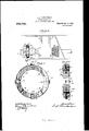
- j j are annular plates with four semi-cylindrical grooves, 70, cut in each plate, as shown in the Shay coupling, so that when said plates are assembled said grooves will form four cylindrical openings, interposed in said plates 90 degrees apart (measuring from their centers), into which openings fit the brass cups or bushings which take the four lugs of the coupling-yokes, L L.
- G represents the tapered double-dove tailed wedge of appropriate dimensions, similar to those used in securing the bevelcogged ear-wheel to the main drive-wheel body in igs. 1., 2. and 3. In securing together the plates j j, any number of these wedges may be employed.
- the combination with a universal shaft-coupling, having two fainnular plates, j 7'', containingsemi-0y Iical grooves, k suited to take the lug;
Description
s. A. BARRIGKMAN.
STEAM LOGOMOTIVB. APPLIOATIOX TILED nn.4.- 1910.
B SHEETS-SHEET 2.
Patented Oct. 11, I910.
UNITED STATES PATENT OFFICE.
SYLVESTER A. BARRICKMAN, OF RIOI-IWOOD, WEST VIRGINIA.
s'rEAM-LoooMoTIvE.
To all whom it may concern:
Be it known that I, SYLvns'rER A. BAR- RICKMAN, a citizen of the United States, residing at Itichwood, in the county of Nicholas and State of West Virginia, have invented certain new and useful Improvements in Steam-Locomotives, fully described and represented in the following specification and accompanying drawings.
My invention relates to beveled-cog drivewheels and universal shaft-couplings, such as are employed in the locomotive engine improved by Shay (Letters Patent No. 242,992, June 14, 1881), Wall and Felghtner (Letters Patent No. 893,041, July 1 1, 1908), and others.
The object. of my invention is to overcome the wear and tear in such wheels and couplings as now manufactured, caused by the shearing of the parts, which shearing, when the engine is in operation, soon cuts the bolts off at the points where the bolted parts oin each other, being the points where the shearing takes place, distorts and enlarges the bolt-holes, necessitates new bolts, the drilling of new holes in the parts, and, ina short time, new parts; and destroys the cupping or bushing in which work the lugs of the coupling-yokes. I attain these objects by means of tapering wedges of steel, of uniform shape and size, containing dovetailed grooves, one in either edge of each wedge, running its entire length, and corresponding mortises cut in the respective parts now secured together with bolts, onehalf of each mortise being cut in each'respective piece; which wedges, being driven into said mortises, are held firmly in place by means of their own friction and by means of set-screws, all of .which are illustrated in the accompanying drawings, in which- Figure 1. is a partly sectional elevation of a drive-wheel of a locomotive engine, with beveled-cog gear-wheel secured to the outside of said drive-wheel; Fig. 2. is a side elevation ofthe outside of the drive-wheel with the beveled-cog gear-wheel removed, showing onehalf of each of four wed es in place in the mortises in the main rivewheel body; Fig. 3. is an end view of the wedge; Fi 4. 1s a side elevation of a universal sha t-coupling joint, such as is employed in a Shay engine, but with my dovetailed wedges in place, secured by setscrews; and Figs. 5. and 6. represent an enlarged-partly sectional elevation of such an Specification of Letters Patent.
Application filed January 4, 1910.
Patented Oct. 11, 1910. Serial No. 536,369.
universal shaft-coupling joint, showing the dove-tailed wedges in position, secured by set-screws.
Similar letters of reference indicate corresponding parts.
In Fig. 1, (2/. represents the axle of a drive- Wheel of a locomotive engine; 6, the main body of the drive-wheels; c, the spokes of the drive-wheel; d, the beveled-cog wheel which gears with the pinion, p- (Fig. 4.); and e, the rim-flange of the beveled-cog Wheel, d, secured to the main drive-wheel body by means of bolts, 7. G represents a wedge of steel, approximately 3" inches in length, 1%" inches thick, 2 inches wide at its head, and tapering uniformly on both edges to a Width of approximately 1%" inches at its point (but may be of any suitable dimensions), and. containing in the center of either edge a dove-tailed groove or channel, of uniform depth, running its entire length. H represents a mortise, onehalf of which is sunk in the main drivewheel body, 6, and the other half of which is sunk into the flange, e, of the beveled-cog gear-wheel, d. Said mortise, H, is cut slightly smaller than the double-dovetailed wedge, Gr, so that the latter may be driven firmly into the former and secured by means of friction and the set-screw, I. Four of these mortises are cut in each wheel, 90 degrees apart (measuring from the center of each mortise), so that when the wheel parts are assembled the eight mortises will form four apertures shaped each to take a doubledovetailed wedge, G.
In Figs. 4., 5. and 6., j j are annular plates with four semi-cylindrical grooves, 70, cut in each plate, as shown in the Shay coupling, so that when said plates are assembled said grooves will form four cylindrical openings, interposed in said plates 90 degrees apart (measuring from their centers), into which openings fit the brass cups or bushings which take the four lugs of the coupling-yokes, L L. G represents the tapered double-dove tailed wedge of appropriate dimensions, similar to those used in securing the bevelcogged ear-wheel to the main drive-wheel body in igs. 1., 2. and 3. In securing together the plates j j, any number of these wedges may be employed. These wedges, as
used in the coupling plates, are driven to 1 ward the center of the annular coupling plates which they secure together, and are held firmly in place by means of their own friction and by means of set-screws, I. With these wedges, G, in place, in wheel and 0011- pling, all strain is taken off of the bolts, f,
and they may be dispensed with entirely; but it is thought that my novel device will prove useful as an auxiliary fastening as well.
I claim:
In a locomotive, the combination; with a universal shaft-coupling, having two fainnular plates, j 7'', containingsemi-0y Iical grooves, k suited to take the lug;
pling-yokes, L L, of tapering d6 Wedges, G, and tapei'in double-dovetailed mortise's, H, out, one-heft in each plate, by means of which wedges and mortises, secured firmly, the one in the other, of their own friction, and with set-screws, I, said plates are held firmly in position and prevented from sheari substantially as herein shown and desori ed.
SYLVESTER A. BARRIGKMAN.
Witnesses: v
HARRY L. BARRICKMAN, J. J. MCCOY.
Priority Applications (1)
| Application Number | Priority Date | Filing Date | Title |
|---|---|---|---|
| US53636910A US972790A (en) | 1910-01-04 | 1910-01-04 | Steam-locomotive. |
Applications Claiming Priority (1)
| Application Number | Priority Date | Filing Date | Title |
|---|---|---|---|
| US53636910A US972790A (en) | 1910-01-04 | 1910-01-04 | Steam-locomotive. |
Publications (1)
| Publication Number | Publication Date |
|---|---|
| US972790A true US972790A (en) | 1910-10-11 |
Family
ID=3041170
Family Applications (1)
| Application Number | Title | Priority Date | Filing Date |
|---|---|---|---|
| US53636910A Expired - Lifetime US972790A (en) | 1910-01-04 | 1910-01-04 | Steam-locomotive. |
Country Status (1)
| Country | Link |
|---|---|
| US (1) | US972790A (en) |
-
1910
- 1910-01-04 US US53636910A patent/US972790A/en not_active Expired - Lifetime
Similar Documents
| Publication | Publication Date | Title |
|---|---|---|
| US2307556A (en) | Drive mechanism for sludge collectors | |
| US972790A (en) | Steam-locomotive. | |
| US1182905A (en) | Flexible shaft-coupling. | |
| US1283787A (en) | Flexible shaft and universal coupling therefor. | |
| US1326993A (en) | Flexible shaft-coupling | |
| US4353606A (en) | Mounting for a driven wheel | |
| US1948473A (en) | Generator drive assembly | |
| GB191108470A (en) | Improvements in Couplings for Shafting and the like. | |
| US2007811A (en) | Adjustable tractor wheel | |
| US1804193A (en) | Generator axle-drive | |
| US2115958A (en) | Power transmission device | |
| US1836700A (en) | Propeller | |
| US482788A (en) | Friction-wheel | |
| US1422598A (en) | Frictional bushing coupling | |
| US1335740A (en) | Universal joint | |
| US1336985A (en) | Universal joint | |
| US1193499A (en) | Universal joint | |
| US1046937A (en) | Keying device for cutter-heads. | |
| US584483A (en) | Joseph richards | |
| US2414591A (en) | Crusher roll with sectional surface elements | |
| US1663259A (en) | Adjustable coupling | |
| US1176787A (en) | Gear. | |
| US914071A (en) | Sectional gear. | |
| US902523A (en) | Flexible driving mechanism. | |
| GB191024776A (en) | Improvements in Mortice Gear Wheels. |