US1663259A - Adjustable coupling - Google Patents
Adjustable coupling Download PDFInfo
- Publication number
- US1663259A US1663259A US105712A US10571226A US1663259A US 1663259 A US1663259 A US 1663259A US 105712 A US105712 A US 105712A US 10571226 A US10571226 A US 10571226A US 1663259 A US1663259 A US 1663259A
- Authority
- US
- United States
- Prior art keywords
- coupling
- projections
- wedges
- members
- faces
- Prior art date
- Legal status (The legal status is an assumption and is not a legal conclusion. Google has not performed a legal analysis and makes no representation as to the accuracy of the status listed.)
- Expired - Lifetime
Links
- 230000008878 coupling Effects 0.000 title description 55
- 238000010168 coupling process Methods 0.000 title description 55
- 238000005859 coupling reaction Methods 0.000 title description 55
- 238000010276 construction Methods 0.000 description 9
- 230000000295 complement effect Effects 0.000 description 1
- 150000001875 compounds Chemical class 0.000 description 1
- 230000000875 corresponding effect Effects 0.000 description 1
- 230000000694 effects Effects 0.000 description 1
- 239000002184 metal Substances 0.000 description 1
Images
Classifications
-
- F—MECHANICAL ENGINEERING; LIGHTING; HEATING; WEAPONS; BLASTING
- F16—ENGINEERING ELEMENTS AND UNITS; GENERAL MEASURES FOR PRODUCING AND MAINTAINING EFFECTIVE FUNCTIONING OF MACHINES OR INSTALLATIONS; THERMAL INSULATION IN GENERAL
- F16D—COUPLINGS FOR TRANSMITTING ROTATION; CLUTCHES; BRAKES
- F16D1/00—Couplings for rigidly connecting two coaxial shafts or other movable machine elements
- F16D1/12—Couplings for rigidly connecting two coaxial shafts or other movable machine elements allowing adjustment of the parts about the axis
-
- Y—GENERAL TAGGING OF NEW TECHNOLOGICAL DEVELOPMENTS; GENERAL TAGGING OF CROSS-SECTIONAL TECHNOLOGIES SPANNING OVER SEVERAL SECTIONS OF THE IPC; TECHNICAL SUBJECTS COVERED BY FORMER USPC CROSS-REFERENCE ART COLLECTIONS [XRACs] AND DIGESTS
- Y10—TECHNICAL SUBJECTS COVERED BY FORMER USPC
- Y10T—TECHNICAL SUBJECTS COVERED BY FORMER US CLASSIFICATION
- Y10T403/00—Joints and connections
- Y10T403/32—Articulated members
- Y10T403/32254—Lockable at fixed position
- Y10T403/32262—At selected angle
Definitions
- MILTON 1 MORRIS, or BUFFALO, AND EDWARD G. DUBARRY, or HAMBURG, NEW
- This invention relates to coupling devices for transmitting power or motion from a driving to a driven member and which are adjustable to vary the angular relationship of the driving and driven members about their axes.
- the objects of this invention are to provide a coupling of this kind of improved construction which can be easily and accurately adjusted; also to provide a coupling of this kind of strong and rugged construction and in which the parts are so formed as to offer the maximum resistance to crushing; also to improve the construction of ad justable couplings of this kind in other respects hereinafter specified.
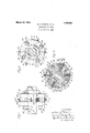
- Fig. 1 is a side elevation of an adjustable coupling embodying this invention.
- Fig. 2 is face view. thereof.
- Fig. 3 is a sectional elevation thereof on line 3-3, Fig. 1. v
- the two parts of the coupling may be connected to driving and driven members of any desired kind, two shafts A, B, being shown in the construction illustrated, either of which may be the driven member, and keys 9 may be used to connect the coupling members to the two shafts.
- '10 and 11 represent the two members of the coupling which are secured by means of the keys 9 to the shafts A, B, respectively.
- Each coupling member is provided with a hub portion 12, and a bore provided with suitable keyways for the keys 9 extends through the hub and body portion of each coupling member to permit each coupling member to be rigidly secured to a shaft. Any other means for securing the members of the coupling to the driving and driven members may be employed, if desired.
- the two adjacent coupling members are provided with sector shaped projections 14 and 15 formed respectively on the coupling memhere 10 and 11, the projections of one cou-.
- pling member extending into the spaces between the projections of the other coupling member so as to form a staggered or alternate arrangement of the projections.
- two projections are formed on each coupling memher, and the adjacent projections are spaced apart so that the spaces between projections are considerably wider circumferentially Serial No. 105,712.
- the oppositely arranged faces of the projections are arranged at an angle to each other so that these faces converge, and preferably these faces extend substantially radiallytoward the axis of I'O tation, and between the substantially radial or converging faces ofthe projections-of the coupling members, wedges are positioned which are movable between-the converging faces, preferably toward and from the axis of the coupling members to adjust these members circumferentially relatively to each other.
- each wedge includes apart 16 having a concave recess l7,'and a part 18 having a convex projection 19adapted to enter'intothe recess 17.
- the outer faces of the Wedges are preferably flat and are adapted tobear'again st the correspond ing radial faces of the projections 14 and 15 and are also adjustable axially relatively to these faces.
- the -meet-ing faces of the convex projection and recess are preferably substantially semi-cylindrical and. afi'ord'a large bearing surf-ace to withstand the stresses produced when power is transmitted through the coupling, and this bearing surface makes it'possible to arrange the outer fiat faces of-the two parts of each wedge member at different angles to each' other.
- any suitable'mea'ns may be provided for from, the axis of rotation of tliecoupl-ing. member.
- threaded bo'ltsfZO are employed for this purpose, the heads 21 of which are suitably held against outward movement, being, as illustrated, arranged in recesses 22 provided in an annular flange 23 formed on the couplingmeniber lland arranged inwardly or toward the axis of rotation with reference to the projections 14 and 15.
- any suitable-means may be provided, if desired, for holding the two coupling members together.
- a plurality of bolts 26 extend through holes in one of the coupling members and through slots 27 in the other member, nuts 28 being provided on the bolts for drawing the two members of the coupling together.
- the slots 27 permit of adjustment of one of the coupling members relatively to the other.
- the nuts 28 are first released to permit the coupling members to move circumferentially relatively to each other.
- Two oppositely disposed wedges are then moved outwardly from the center. or axis of the coupling, and then the alternate wedges are moved toward the cen ter to the same extent to effect adjustment of one of the parts of the coupling member relatively to the other.
- each wedge and the concave and convex faces of thetwo parts thereof afford an ample bearing surface so that a large amount of power may be transmittedfrom one shaft to the other without submitting the wedges or projec tions on the coupling members to strains which might crush or damage the metal of these parts.
- An adjustable coupling including a pair of coupling members, each having projections extending into alternate arrangement with the projections of the other coupling member-about the axis of said coupling, the opposite faces of adjacent projections being inclined relatively to each other, and wedges arranged between said inclined faces and movable to different positions relatively thereto, said wedges each including a part having a convex substantially cylindrical portion adapted to interfit with a concave substantially cylindrical'portion of the other wedge part topermit an angular adjustment of said parts to the wedge relatively to each other about centers extending substantially parallel to the axis of the coupling.
- An adjustable coupling including two members each having projections extending into staggered relation to the projections of the other coupling member, wedges arranged between adjacent projections, each of said wedges being formed of two parts having interfitting portions substantially coextensive with the lengths of said wedges and enabling the parts of the wedges to swing into different angular relations to each other about axes substantially parallel with the axis of the coupling, and means for adjusting said wedges into different relations to said projections to vary the adjustment of said coupling members relatively to each other.
- a coupling including a pair of coupling members each having projections extending into alternate -.irrangement with the projections of the other coupling member about the axis of said coupling, wedges arranged between adjacent projections and including two parts, each part having a substantially flat face adapted to engage an inclined face of saidcoupling and a substantially cylindrical face adapted to interfit with a com plementary cylindrical face of the other part of the wedge, to permit of angular adjustment of said parts only about axes substantially parallel to the axis of said coupling, and means engaging one of said wedge parts for adjusting said wedge relatively to said projectigns.
- a coupling including a pair of coupling members each having projections ex tending into alternate arrangement with the projections of the other coupling member about the axis of said coupling, wedges arranged between adjacent projections and ineluding two parts, one part having a flat outer face and a substantially cylindrical concave inner face and the other part having a flat outer face and a substantially cylindrical convex inner face fitting into the concave face of said other part, and a separate adjusting screw for each wedge, each adjustableting screw engaging one part of a wedge for moving the same into different relations to the inclined facesof said projections toward and from the axis of said coupling said parts relatively to each other only about i axes substantially parallel with the axis of the coupling, and means for clamping said two coupling members together in their adjusted positions.
Landscapes
- Engineering & Computer Science (AREA)
- General Engineering & Computer Science (AREA)
- Mechanical Engineering (AREA)
- Prostheses (AREA)
Description
1 March 20, 1928.
-M. D. MORRIS ET 1.
ADJUSTABLE COUPLING Filed April 30. 1926 Patented Mar. 26, 1928.
UNITE 21,
tease MILTON 1). MORRIS, or BUFFALO, AND EDWARD G. DUBARRY, or HAMBURG, NEW
YORK.
ADJUSTABLE COUPLING.
Application filed April 30, 1926.
This invention relates to coupling devices for transmitting power or motion from a driving to a driven member and which are adjustable to vary the angular relationship of the driving and driven members about their axes.
The objects of this invention are to provide a coupling of this kind of improved construction which can be easily and accurately adjusted; also to provide a coupling of this kind of strong and rugged construction and in which the parts are so formed as to offer the maximum resistance to crushing; also to improve the construction of ad justable couplings of this kind in other respects hereinafter specified.
In the accompanying drawings,
Fig. 1 is a side elevation of an adjustable coupling embodying this invention.
Fig. 2 is face view. thereof.
Fig. 3 is a sectional elevation thereof on line 3-3, Fig. 1. v
The two parts of the coupling may be connected to driving and driven members of any desired kind, two shafts A, B, being shown in the construction illustrated, either of which may be the driven member, and keys 9 may be used to connect the coupling members to the two shafts. '10 and 11 represent the two members of the coupling which are secured by means of the keys 9 to the shafts A, B, respectively. Each coupling member is provided with a hub portion 12, and a bore provided with suitable keyways for the keys 9 extends through the hub and body portion of each coupling member to permit each coupling member to be rigidly secured to a shaft. Any other means for securing the members of the coupling to the driving and driven members may be employed, if desired.
In the particular construction shown the two adjacent coupling members are provided with sector shaped projections 14 and 15 formed respectively on the coupling memhere 10 and 11, the projections of one cou-.
pling member extending into the spaces between the projections of the other coupling member so as to form a staggered or alternate arrangement of the projections. In the particularconstruction shown, two projections are formed on each coupling memher, and the adjacent projections are spaced apart so that the spaces between projections are considerably wider circumferentially Serial No. 105,712.
than the projections. The oppositely arranged faces of the projections are arranged at an angle to each other so that these faces converge, and preferably these faces extend substantially radiallytoward the axis of I'O tation, and between the substantially radial or converging faces ofthe projections-of the coupling members, wedges are positioned which are movable between-the converging faces, preferably toward and from the axis of the coupling members to adjust these members circumferentially relatively to each other. Since an adjustment of one coupling member relatively to the other one changes the angle between adjacent faces of the projections 14 and 15, the wedges are preferably made in two parts whichar'e capableof adjustment relatively to each other so-compensate for variations in this angleand which are'so formed as to trans initheavy forces from one part of a Wedge block to the other part. In the construction shown for this purpose each wedge includes apart 16 having a concave recess l7,'and a part 18 having a convex projection 19adapted to enter'intothe recess 17. The outer faces of the Wedges are preferably flat and are adapted tobear'again st the correspond ing radial faces of the projections 14 and 15 and are also adjustable axially relatively to these faces. The -meet-ing faces of the convex projection and recess are preferably substantially semi-cylindrical and. afi'ord'a large bearing surf-ace to withstand the stresses produced when power is transmitted through the coupling, and this bearing surface makes it'possible to arrange the outer fiat faces of-the two parts of each wedge member at different angles to each' other.
Any suitable'mea'ns may be provided for from, the axis of rotation of tliecoupl-ing. member. In the particular construction shown threaded bo'ltsfZO are employed for this purpose, the heads 21 of which are suitably held against outward movement, being, as illustrated, arranged in recesses 22 provided in an annular flange 23 formed on the couplingmeniber lland arranged inwardly or toward the axis of rotation with reference to the projections 14 and 15. These adadjusting the compound wedges toward and I justing'bolts or screws are provided at their outer ends with'po'rtions adapted to be engaged by a wrench or other tool for turnin'g thesame and since each ofthese bolts has a threaded engagement with the part 18 of a wedge, it will be obvious that the turning of the bolts will produce a radial movement of the wedges. 24 represents lock nuts which are adapted to hold the bolts in their adjusted positions.
Any suitable-means may be provided, if desired, for holding the two coupling members together. In the construction shown for this purpose a plurality of bolts 26 extend through holes in one of the coupling members and through slots 27 in the other member, nuts 28 being provided on the bolts for drawing the two members of the coupling together. The slots 27 permit of adjustment of one of the coupling members relatively to the other.
In order to adjust the coupling, the nuts 28 are first released to permit the coupling members to move circumferentially relatively to each other. Two oppositely disposed wedges are then moved outwardly from the center. or axis of the coupling, and then the alternate wedges are moved toward the cen ter to the same extent to effect adjustment of one of the parts of the coupling member relatively to the other.
During the operation of the coupling member the opposite fiat faces of each wedge and the concave and convex faces of thetwo parts thereof afford an ample bearing surface so that a large amount of power may be transmittedfrom one shaft to the other without submitting the wedges or projec tions on the coupling members to strains which might crush or damage the metal of these parts.
1 By means of the construction shown, an accurate and delicate adjustment of the two coupling members can be effected by turning of the adjusting screws of t-he wedges.
e claim as our invention 1. An adjustable coupling including a pair of coupling members, each having projections extending into alternate arrangement with the projections of the other coupling member-about the axis of said coupling, the opposite faces of adjacent projections being inclined relatively to each other, and wedges arranged between said inclined faces and movable to different positions relatively thereto, said wedges each including a part having a convex substantially cylindrical portion adapted to interfit with a concave substantially cylindrical'portion of the other wedge part topermit an angular adjustment of said parts to the wedge relatively to each other about centers extending substantially parallel to the axis of the coupling.
2. An adjustable coupling including two members each having projections extending into staggered relation to the projections of the other coupling member, wedges arranged between adjacent projections, each of said wedges being formed of two parts having interfitting portions substantially coextensive with the lengths of said wedges and enabling the parts of the wedges to swing into different angular relations to each other about axes substantially parallel with the axis of the coupling, and means for adjusting said wedges into different relations to said projections to vary the adjustment of said coupling members relatively to each other.
3. A coupling including a pair of coupling members each having projections extending into alternate -.irrangement with the projections of the other coupling member about the axis of said coupling, wedges arranged between adjacent projections and including two parts, each part having a substantially flat face adapted to engage an inclined face of saidcoupling and a substantially cylindrical face adapted to interfit with a com plementary cylindrical face of the other part of the wedge, to permit of angular adjustment of said parts only about axes substantially parallel to the axis of said coupling, and means engaging one of said wedge parts for adjusting said wedge relatively to said projectigns.
4. A coupling including a pair of coupling members each having projections ex tending into alternate arrangement with the projections of the other coupling member about the axis of said coupling, wedges arranged between adjacent projections and ineluding two parts, one part having a flat outer face and a substantially cylindrical concave inner face and the other part having a flat outer face and a substantially cylindrical convex inner face fitting into the concave face of said other part, and a separate adjusting screw for each wedge, each adusting screw engaging one part of a wedge for moving the same into different relations to the inclined facesof said projections toward and from the axis of said coupling said parts relatively to each other only about i axes substantially parallel with the axis of the coupling, and means for clamping said two coupling members together in their adjusted positions.
MILTON D. MORRIS. EDWARD G. DU BARRY.
Priority Applications (1)
| Application Number | Priority Date | Filing Date | Title |
|---|---|---|---|
| US105712A US1663259A (en) | 1926-04-30 | 1926-04-30 | Adjustable coupling |
Applications Claiming Priority (1)
| Application Number | Priority Date | Filing Date | Title |
|---|---|---|---|
| US105712A US1663259A (en) | 1926-04-30 | 1926-04-30 | Adjustable coupling |
Publications (1)
| Publication Number | Publication Date |
|---|---|
| US1663259A true US1663259A (en) | 1928-03-20 |
Family
ID=50069348
Family Applications (1)
| Application Number | Title | Priority Date | Filing Date |
|---|---|---|---|
| US105712A Expired - Lifetime US1663259A (en) | 1926-04-30 | 1926-04-30 | Adjustable coupling |
Country Status (1)
| Country | Link |
|---|---|
| US (1) | US1663259A (en) |
Cited By (1)
| Publication number | Priority date | Publication date | Assignee | Title |
|---|---|---|---|---|
| DE9110180U1 (en) * | 1991-08-16 | 1991-09-26 | MBK Maschinenbau Kiefersfelden GmbH, 8205 Kiefersfelden | Angle correction device |
-
1926
- 1926-04-30 US US105712A patent/US1663259A/en not_active Expired - Lifetime
Cited By (1)
| Publication number | Priority date | Publication date | Assignee | Title |
|---|---|---|---|---|
| DE9110180U1 (en) * | 1991-08-16 | 1991-09-26 | MBK Maschinenbau Kiefersfelden GmbH, 8205 Kiefersfelden | Angle correction device |
Similar Documents
| Publication | Publication Date | Title |
|---|---|---|
| SU1558308A3 (en) | Shaft joint | |
| US2319100A (en) | Constant velocity joint | |
| US1663259A (en) | Adjustable coupling | |
| US1612769A (en) | Expansible locking key | |
| US2727369A (en) | Flexible shaft-coupling | |
| US1316011A (en) | bailey and g | |
| US1675065A (en) | Flexible shaft coupling | |
| US2453964A (en) | Coupling for shafts | |
| US1579967A (en) | Flexible shaft coupling | |
| US1791763A (en) | Flexible coupling | |
| US1337642A (en) | Shaft-coupling | |
| US2815231A (en) | Threaded nut ring for shaft coupling | |
| US1326993A (en) | Flexible shaft-coupling | |
| US1271905A (en) | Universal coupling. | |
| US2343332A (en) | Impact clutch | |
| US2411600A (en) | Overload clutch | |
| US1156493A (en) | Shaft-coupling. | |
| US2884772A (en) | Rotary torque transmitting joint | |
| US1345735A (en) | Coupling | |
| US3759065A (en) | Keyed joint | |
| US1242906A (en) | Shaft-coupling. | |
| US2220799A (en) | Coupling | |
| US1408041A (en) | Shaft coupling | |
| US1309826A (en) | Universal joint. | |
| US2236839A (en) | Universal joint |