US972722A - Weft-replenishing loom. - Google Patents
Weft-replenishing loom. Download PDFInfo
- Publication number
- US972722A US972722A US53404909A US1909534049A US972722A US 972722 A US972722 A US 972722A US 53404909 A US53404909 A US 53404909A US 1909534049 A US1909534049 A US 1909534049A US 972722 A US972722 A US 972722A
- Authority
- US
- United States
- Prior art keywords
- bobbin
- filling
- lever
- slide
- engage
- Prior art date
- Legal status (The legal status is an assumption and is not a legal conclusion. Google has not performed a legal analysis and makes no representation as to the accuracy of the status listed.)
- Expired - Lifetime
Links
- 230000007246 mechanism Effects 0.000 description 19
- 239000011435 rock Substances 0.000 description 6
- 238000010276 construction Methods 0.000 description 3
- 239000000835 fiber Substances 0.000 description 2
- 239000004576 sand Substances 0.000 description 2
- 101150092509 Actn gene Proteins 0.000 description 1
- 244000228957 Ferula foetida Species 0.000 description 1
- 240000001973 Ficus microcarpa Species 0.000 description 1
- 241000234435 Lilium Species 0.000 description 1
- HEMHJVSKTPXQMS-UHFFFAOYSA-M Sodium hydroxide Chemical compound [OH-].[Na+] HEMHJVSKTPXQMS-UHFFFAOYSA-M 0.000 description 1
- 210000000481 breast Anatomy 0.000 description 1
- QDERNBXNXJCIQK-UHFFFAOYSA-N ethylisopropylamiloride Chemical compound CCN(C(C)C)C1=NC(N)=C(C(=O)N=C(N)N)N=C1Cl QDERNBXNXJCIQK-UHFFFAOYSA-N 0.000 description 1
- 239000002184 metal Substances 0.000 description 1
- 239000007787 solid Substances 0.000 description 1
Images

Classifications
-
- D—TEXTILES; PAPER
- D03—WEAVING
- D03D—WOVEN FABRICS; METHODS OF WEAVING; LOOMS
- D03D51/00—Driving, starting, or stopping arrangements; Automatic stop motions
- D03D51/18—Automatic stop motions
- D03D51/34—Weft stop motions
Definitions
- ho filling detector or lieeler is adapted to feel through an opening in the front wall of the shuttle and engage with the lilling on the bobbin iu the active Elli/ill tle, and on the substantial exhaustion of filling to put into operation mt'ichanism to cause the weft replenishing;- mechanism to supply a fresh bobbin in place of the substantially exhausted bobbin, in the usual and well known way.
- the object of my invention is to improve upon the construction of filling detector mechanisms of the class referred to, and more nirticularly toprovide a very sensitive and delicate detector mechanism, having a i'eeler which will feel for and de teet. the praetieal or substantial exhaustion of lilting on the bobbin without regard to the size. of the bobbin on which. the filling is wound, or the position of the bobbin inthe shuttle.
- a feelerdcviee consisting of two members.
- One of said members is in the form of a slide suitably guided in a stand, and is yicldingly held against the lilliug on the bobbin on the fol-11rd movement oi the lay, and move. with the bobbin a certain distance toward the front of the loom as the lay beats up: said sliding member has preferably a broad engaging surf-ice, preferably rectangular in shape, relative. to the. length oi the bobbin, to engage the bobbin on its greatest diameter. The movement of the slide toward the breast beam or the front of the.
- loom causes a lever, to be hereinafter described, to be rocked, which causes the pivot point of an operating;- lever to be removed, and leaves the replenishing mechanism .at rest as long as a. sullicient amount of filling is left on the bobbin.
- angle lever which is suitably pivoted on the first memher or slide. and has its engagingend located in substantially the same lmrizontal plane as the. engaging end of the lirst mew tioned member of the fender device.
- nc arm of the angle lever extends preferably is also adapted to engage the filling on the bobbin.
- the end of Saidarm is in this ino stance tn'eferably provided with short bristles forming a brush surface. which will, in engaging the bobbin, penetrate the filling; without spoiling or inj'urin' the yarn. in my ii'eeler device, one ot the .lilling; engaging portions is adapted to be.
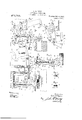
- FIG. l is an end view of a detached portion of a Weft replenishing loom, with my improved filling detector mechanism combined therewith, looking in the direction of arrow a, Fig. 7 the lay, shuttle, and bobbin are shown in see tion. and the magazine shown in Fig. 7 is not shown in this figure.
- Fig. 2 shows some of the parts detached, which are not fully shown in Fig. 1.
- Fig. 3 is a plan viewer the filling feeler or detector, looking in the direction of HII'OXOV 7), Fig. 1, the transferrer arm shown in F ig. l is leftott in this figure.
- Fig. 4c shows the sliding part (it the feeler mechanism shown in Fig. 3, detached, and.
- Fig. is afront View of the feeler slide, detached, looting in the direction of arrow 0.
- Fig. 9 is a section through the feeler slide, detached, on line 6, (3, Fig. 4t, looking in the direction of arrow 0, same figure.
- Fig. 7 is a front View of the parts shown in Fig. 1, looking in the direction of arrow (l, same figure, and also shows a stationary magazine and other parts of the type shown and described in said Letters Patent, No. 933,492, and, Fig. 8 is a detached portion of the stationary magazine shown in Fig. 7, showing a locking device for the upright bars combined therewith.
- the stud 3 is provided with a bushing a, preferably secured thereon by a nut 5 see Fig. 5.
- the bushing 4 has adjustably secured thereon by a bolt 6, see Fig. 1, the clamping portion 7 of the t'eeler guide 7.
- the guide 7 preferably rests with its end upon an adiusting screw 8, and is grooved to loosely'receive the feelcr slide 9.
- a cap 10 is preferably secured upon the guide 7 by screws 11.
- the feeler'slide 9 is made in this instance of thin sheet metal, forming an oblong hollow member, see Fig. 5, which has a solid engaging end 9, with one or' more wedge shaped surfaces, adapted to an gage the bobbin 12 in the shuttle 13, through an opening 13 in the side of said shuttle, as shown in Fig. 3.
- the teeler slide 9 is one member of the feeler device, and the engagin end 9' is elongated or of considerable thickness, as shown in Fig. l, to engage a considerable surface of the filling, transversely of the bobbin.
- the slide 9 is provided With 9. lug 9", to hold the wire or rod 14 which extends through a lug 10 on the cap 10.
- a helically coiled expansion spring 15 encircles the rod 14, and bears at one end against the lug 10 on the cap 10, and at its other end against the lug 9 of the slide 9, and acts to yieldingly move the slide 9 toward the bobbin 12 in the shuttle 13, to engage with the filling 12 on said bobbin.
- An adjusting screw 16, which turns in a threaded. hole in an extension 10 on the inner end of the cap 10, serves to regulate the outward movement of the slide 9.
- vulcanized fiber may be substitute-d.
- the second arm 17 of the angle lever 17 is oivotally connected to one end of a connc rod or wire 18, see 3 and 4-. and the other end OfStllCl rod 18 is "otally connected to the end of upright lever 19, F l, which has its hub 19 fast on a shaft 26 which loosely mounted in bosses 2 2 on the stand 2.
- a helicallv coiled torsion spring 21 encircles the sham; 20, and has one end connected with the hoss. 2, and the other end connected to a 22 fast on the shaft 20, see Fig. 5.
- the torsion SDZTiIlD' rocks the shaft i 4 L a and moves the lever 19, and the rod 18 attached thereto, to operate the angle lever 1?", when the slide 9, upon its engagementwith the bobbin 12, is moved toward the front of the loom. If there is not a suftlcient amount of fil ing 12 on'the bobbin 12 to hold the brush portion 1? on the lever '17, the engaging of said lever 1'4" will move outwardly, as shown in Fig. 3, and the upright lever will remain stationary in the position shown in Figs. 1 and The other end of the shaft 20 has secured thereon the hub 23 of an upright lever 23.
- the upper end of the upright l ver 23 is pivotally connected with the end of a horizontally extending rod 24;, see Fig. 3, which is loosely guided in the enlarged portion 2 the stand 2.
- the rod 24 extends into the lower part of the slotted recess in the stand F2, see l, and is adapted to form a rest or support for the end or a horizontally extending lever 25, which extends'into the slotted portion 2 and rests upon the end of the rod 24, see Fig. 5.
- the lever 25 has a vertical reciprocating movement commnni cated thereto from some driven part of the loom, not shown, through a connector 26 provided with a rod-head 26, which is loosely guiced in the boss 2 on the stand 52.
- the rod-head 26 carries a stud 27 on which the lever 25 is pivotally mounted, see Fi
- the other end of the lever 25 is pivotally connected to the lower end of an upwardly extendin connector 28, and the upper end of said connector 28 is pivotally connected to the end of a rocking lever 29, which op lever 30, to raise the upright bar 521 to rock the cradle 32, s e (5, all as .1.
- the upright bar or bars 31 have the Weighted hooks; 36 thereon, and the downward motion of a bar 31, through the engagement oil a hook with a lever 37 l'aei: on a rocks rock shaf 38, moves said lever and. said. iii ft 38.
- i. stud 4-0 on the arm enters a hole in ublocl: it, which. is adapted to loosely slide in an elongated opening l2 in a lever 42, which has its hub 42f loosely mounted on a stud 43.
- helically coiled expansion spring 44 bears at one end against the block 41. and at its other end against the hub 4-22 on the [ever 42, and acts to hold and lock the lovers: 3? and fit) in their upper and lower position.
- the lower end of the connector 4;? is connected to one arm 48' of a lever 48. which has its hub loosely mounted on the hub of the traneferrer arm etfiueee Figs. .l and 2. Tlie'otlieir arm 4 of the lGVBl.
- pin SG-"tliereoii. ⁇ Vltltill es:- tends into the iot 51 in one end of a downwardly or. n; 11g conuecto- 51.
- the other end of elite. counea'ztor 531 LS plvotally-c elected to an extension. 52 on the hunter 1 the rod-lined 4.6 on the i direction of the length of the bobbin when the ruling on sand bobbin has been subsl-air.
- said lJllllltl 52 is adapted to be raised. from the position shown in full lines to the position shown in broken lines in Fig. 2. through the connections above rcl'crrcd to. so that said hunter 52 will be in position to laengagcd by the dagger 53, carried on the lay. see Fig. 1, to operate the transferrciarm -13) and the trausfei'iicr l9 tlicreoi'i. to transfer n bobbin. It stud Bl get-tired to the stand 7''. nee l ig. 2, limits tll-v upward movement ol the hunter 52.
- a n'icznbcr having a wedge shaped elongated or thickened end to engage the bobbin trai'isversely of its length, a second member to engage the filling. pivoted on Stlhl first. mentioned member. and having its eugaging end in sul'istantially the same. horizontal plane as the engaging end. oi said first mentioned .mcitibcr. said second men tioned member adapted to swing on its pivot attachment in the direction of the length of the bobbin when the filling on the bobbin has been substantially exhausted.
- a member to engage the filling on the bobbin in the active shuttle a. second member having a yielding friction surl'acc to cm gage the filling on said bobbim and pivoted on said first mentioned member, said second mentioned member adapted to mviug in the tially exhausted.
- a tilting detecting mechanism for looms a member to engage the filling on the bobbin in the active shuttle.
- a. second member having o. brush or bristles on its engag iug end to engage the lillmg on said bobbin, and pivoted on said first. mentioned member.
- T. in 2 filling detecting mechanism fur looms, as hwllmv recipromting nmnzl hmng engig 111g 31th a. l 211mm: to
- member 1- two mem- 7 pnuiuns, id members email: with. lhe. filling in the 7. .hei's i0 impinge w oily- 1, having a 4mm bgtween the 1:-;1.'sn.-:ely 0i fihe lagih of an 1 kid gag' mg peratm l m b (i z from and lllC- oiizor 6115.511; pmilc-n, 1n the ilil'wtiun o; g carrier.
Landscapes
- Engineering & Computer Science (AREA)
- Textile Engineering (AREA)
- Looms (AREA)
Description
UhlliTiED %TATE@ RANT @Ffiliilbi. I
EIPA H. RYON, OF VFORCESTEB. MAISSACHUSETTS, ASSIGNOR- TO CRGMPTON 8c KNOWiZ-ES LOUM WORKS, A CORPORATION OF IVIASSACHUSETTS.
W'EFT-REPLENISI-IING LOOM.
Specification of Letters Patent.
Application filed December 20. 1909.
Patented 'Uct. ill, will.
Serial No. 534.049.
To all whom 'it'mai concern:
lie it known that I, EPPA H. RYON, a citizen of the l mited States, residing at oreester, in the county of lVorcester and State of Massachusetts, have invented eertain new and useful Improvements in \Veit Replenishiug Looms, of which the following is a specifieatimi.
lily invention relates to weft replenishing looms, and more particularly to a filling detector or feeler mechanism for weft replenishintlooms. which is preferi'dily located at the magazine end of the loom,on the loom side or end frame. ho filling detector or lieeler is adapted to feel through an opening in the front wall of the shuttle and engage with the lilling on the bobbin iu the active Elli/ill tle, and on the substantial exhaustion of filling to put into operation mt'ichanism to cause the weft replenishing;- mechanism to supply a fresh bobbin in place of the substantially exhausted bobbin, in the usual and well known way.
The object of my invention "is to improve upon the construction of filling detector mechanisms of the class referred to, and more nirticularly toprovide a very sensitive and delicate detector mechanism, having a i'eeler which will feel for and de teet. the praetieal or substantial exhaustion of lilting on the bobbin without regard to the size. of the bobbin on which. the filling is wound, or the position of the bobbin inthe shuttle.
in my improvements I provide a feelerdcviee consisting of two members. One of said members is in the form of a slide suitably guided in a stand, and is yicldingly held against the lilliug on the bobbin on the fol-11rd movement oi the lay, and move. with the bobbin a certain distance toward the front of the loom as the lay beats up: said sliding member has preferably a broad engaging surf-ice, preferably rectangular in shape, relative. to the. length oi the bobbin, to engage the bobbin on its greatest diameter. The movement of the slide toward the breast beam or the front of the. loom causes a lever, to be hereinafter described, to be rocked, which causes the pivot point of an operating;- lever to be removed, and leaves the replenishing mechanism .at rest as long as a. sullicient amount of filling is left on the bobbin.
The second member of the feeler device toward the engaging end of the slide, and
consists in this instance of an angle lever. which is suitably pivoted on the first memher or slide. and has its engagingend located in substantially the same lmrizontal plane as the. engaging end of the lirst mew tioned member of the fender device. )nc arm of the angle lever extends preferably is also adapted to engage the filling on the bobbin. The end of Saidarm is in this ino stance tn'eferably provided with short bristles forming a brush surface. which will, in engaging the bobbin, penetrate the filling; without spoiling or inj'urin' the yarn. in my ii'eeler device, one ot the .lilling; engaging portions is adapted to be. moved away from and toward the other filling engaging portion, in the direction or the. bobbin or filling 'arrier. Upon the engagement of the bobbin by the tfeeler, both members will move in unison until substantial exhaustion of the filling is reached. Upon the substantial exhaustion offilling on the bobbin, When the sliding member engages the bobbin, there will not be a sufiicient amount of filling on the. bobbin to hold the. arm of the second member or angle lever stationary, this will allow said arm to move freely sidcwise, and through connections to a lever, hereinafter described, cause said lever to remain in its position and not act to withdraw the pivoted point of the. operating lever of the re. plenishing mechanism, and a fresh bobbin will be. dropped from the magazine in the usual way.
l have shown in the drawings a detached portion of a statiomu-y magazine, and some of the operating parts, of the type shown and described in U. S. Letters Patent No. 933,492, dated September 7, i909, with my improvements combined therewith, sufiicient to enable those skilled in the art to understand the construction and operation thereof.
Referring to the drawings :-Figure l is an end view of a detached portion of a Weft replenishing loom, with my improved filling detector mechanism combined therewith, looking in the direction of arrow a, Fig. 7 the lay, shuttle, and bobbin are shown in see tion. and the magazine shown in Fig. 7 is not shown in this figure. Fig. 2 shows some of the parts detached, which are not fully shown in Fig. 1. Fig. 3 is a plan viewer the filling feeler or detector, looking in the direction of HII'OXOV 7), Fig. 1, the transferrer arm shown in F ig. l is leftott in this figure. Fig. 4c shows the sliding part (it the feeler mechanism shown in Fig. 3, detached, and. in a different position. Fig. is afront View of the feeler slide, detached, looting in the direction of arrow 0, Fig. l. Fig. 9 is a section through the feeler slide, detached, on line 6, (3, Fig. 4t, looking in the direction of arrow 0, same figure. Fig. 7 is a front View of the parts shown in Fig. 1, looking in the direction of arrow (l, same figure, and also shows a stationary magazine and other parts of the type shown and described in said Letters Patent, No. 933,492, and, Fig. 8 is a detached portion of the stationary magazine shown in Fig. 7, showing a locking device for the upright bars combined therewith.
I will first describe my improvements in filling detector mechanism.
Secured to the loom side 1 and extending out therefrom, l1. stand 2, having a boss 2 and a stud orvbolt 3 thereon, Figs. 1 and 2. The stud 3 is provided with a bushing a, preferably secured thereon by a nut 5 see Fig. 5. The bushing 4 has adjustably secured thereon by a bolt 6, see Fig. 1, the clamping portion 7 of the t'eeler guide 7. The guide 7 preferably rests with its end upon an adiusting screw 8, and is grooved to loosely'receive the feelcr slide 9. A cap 10 is preferably secured upon the guide 7 by screws 11. The feeler'slide 9 is made in this instance of thin sheet metal, forming an oblong hollow member, see Fig. 5, which has a solid engaging end 9, with one or' more wedge shaped surfaces, adapted to an gage the bobbin 12 in the shuttle 13, through an opening 13 in the side of said shuttle, as shown in Fig. 3. The teeler slide 9 is one member of the feeler device, and the engagin end 9' is elongated or of considerable thickness, as shown in Fig. l, to engage a considerable surface of the filling, transversely of the bobbin. The slide 9 is provided With 9. lug 9", to hold the wire or rod 14 which extends through a lug 10 on the cap 10. A helically coiled expansion spring 15 encircles the rod 14, and bears at one end against the lug 10 on the cap 10, and at its other end against the lug 9 of the slide 9, and acts to yieldingly move the slide 9 toward the bobbin 12 in the shuttle 13, to engage with the filling 12 on said bobbin. An adjusting screw 16, which turns in a threaded. hole in an extension 10 on the inner end of the cap 10, serves to regulate the outward movement of the slide 9. By the engagement of the engaging end of the slide 9 with the bobbin 12 in the shuttle 13, a backward sliding movement is communicated to said slide every other pick, when the lay heats up.
Within the hollow part of the slide '9 is in this instance located the second surface, vulcanized fiber may be substitute-d. The second arm 17 of the angle lever 17 is oivotally connected to one end of a connc rod or wire 18, see 3 and 4-. and the other end OfStllCl rod 18 is "otally connected to the end of upright lever 19, F l, which has its hub 19 fast on a shaft 26 which loosely mounted in bosses 2 2 on the stand 2. A helicallv coiled torsion spring 21 encircles the sham; 20, and has one end connected with the hoss. 2, and the other end connected to a 22 fast on the shaft 20, see Fig. 5. The torsion SDZTiIlD' rocks the shaft i 4 L a and moves the lever 19, and the rod 18 attached thereto, to operate the angle lever 1?", when the slide 9, upon its engagementwith the bobbin 12, is moved toward the front of the loom. If there is not a suftlcient amount of fil ing 12 on'the bobbin 12 to hold the brush portion 1? on the lever '17, the engaging of said lever 1'4" will move outwardly, as shown in Fig. 3, and the upright lever will remain stationary in the position shown in Figs. 1 and The other end of the shaft 20 has secured thereon the hub 23 of an upright lever 23. The upper end of the upright l ver 23 is pivotally connected with the end of a horizontally extending rod 24;, see Fig. 3, which is loosely guided in the enlarged portion 2 the stand 2. The rod 24: extends into the lower part of the slotted recess in the stand F2, see l, and is adapted to form a rest or support for the end or a horizontally extending lever 25, which extends'into the slotted portion 2 and rests upon the end of the rod 24, see Fig. 5. The lever 25 has a vertical reciprocating movement commnni cated thereto from some driven part of the loom, not shown, through a connector 26 provided with a rod-head 26, which is loosely guiced in the boss 2 on the stand 52. The rod-head 26 carries a stud 27 on which the lever 25 is pivotally mounted, see Fi The other end of the lever 25 is pivotally connected to the lower end of an upwardly extendin connector 28, and the upper end of said connector 28 is pivotally connected to the end of a rocking lever 29, which op lever 30, to raise the upright bar 521 to rock the cradle 32, s e (5, all as .1.
a "ally described in said i Patent, No.
fit)
933,492, above referred to, to release it bobbin from the magazine preparatory to being transferred into the active shuttle, in. the usual way.
ll :1 bobbin 12 in the shuttle 13 provided with a suliicii-rnt amount; of filling, the brush portion 17'. on the engagii'ig end of the lever 17, carried on the slide u. will pcnetrate the filling. as shown in Fig. i, and the angle lever 17 will remain in the same position relative to the slide 9. and through the backward sliding nmvcment of the slide 9, through its engagement with the filling on the bobbin. the. la} beats up. the wire 15%" will move the upright lever 15), and rock the shaft 20, and through the upright; lever 23 will move the horizontally extending rod or Wire 24:, and withdraw the same from the slotted part 2, and out of the path of the end of the lever 25, and allow said lever to move downwardly with the connector and not to move the upright connector 38 and the rocking lever 29, to rock the cradle 32, all as will be readily understood by those skilled in the art. i
will now describe my iinl'n'ovcmcnts in mechanism for locl-zing l w cradle Ii; in in; position. spring actuated plunger ii-3, race Fig. 6, is euitiibly guided in a stand 3-1 on v the magazine. The inner engm rig end 33 of the plunger no enters; notch .31 in the upright bar 31 to lock said bar inits upper and lower position, as required, to operate the cradle 32. its shown and described in U. S. Letters Patent, No. 933,492, above referred to, the upright bar or bars 31 have the Weighted hooks; 36 thereon, and the downward motion of a bar 31, through the engagement oil a hook with a lever 37 l'aei: on a rocks rock shaf 38, moves said lever and. said. iii ft 38. The outer end oi the b hit.) 1 tl'lereto the hub 31) of H11 arm 39, :e 1g. 5. i. stud 4-0 on the arm enters a hole in ublocl: it, which. is adapted to loosely slide in an elongated opening l2 in a lever 42, which has its hub 42f loosely mounted on a stud 43. It, helically coiled expansion spring 44 bears at one end against the block 41. and at its other end against the hub 4-22 on the [ever 42, and acts to hold and lock the lovers: 3? and fit) in their upper and lower position. llxtcmliug out from the hub 42'' oi? the lever "if-2 is a second arm 443, the outer end of which pivotnlly connected upper end oil? a connector ll. The lower end of the connector 4;? is connected to one arm 48' of a lever 48. which has its hub loosely mounted on the hub of the traneferrer arm etfiueee Figs. .l and 2. Tlie'otlieir arm 4 of the lGVBl. pin SG-"tliereoii. \Vltltill es:- tends into the iot 51 in one end of a downwardly or. n; 11g conuecto- 51. The other end of elite. counea'ztor 531 LS plvotally-c elected to an extension. 52 on the hunter 1 the rod-lined 4.6 on the i direction of the length of the bobbin when the ruling on sand bobbin has been subsl-air.
and said lJllllltl 52 is adapted to be raised. from the position shown in full lines to the position shown in broken lines in Fig. 2. through the connections above rcl'crrcd to. so that said hunter 52 will be in position to laengagcd by the dagger 53, carried on the lay. see Fig. 1, to operate the transferrciarm -13) and the trausfei'iicr l9 tlicreoi'i. to transfer n bobbin. It stud Bl get-tired to the stand 7''. nee l ig. 2, limits tll-v upward movement ol the hunter 52.
it will be understood that the details of construction of my improvements tray be varied if desired. Instead of having a brush portion or bristles 17 on the fillingeugagmg end of the :2 igle lever 17, forming the second member of the feelcr device I may provide said end with any other suitable friction surface, as vulcanized fiber.
7 Having thus describml my invention. what I claim as new and desire to secure by Lettcre Patient. is:
fl. in a filling detecting mechanism for looms. a n'icznbcr having a wedge shaped elongated or thickened end to engage the bobbin trai'isversely of its length, a second member to engage the filling. pivoted on Stlhl first. mentioned member. and having its eugaging end in sul'istantially the same. horizontal plane as the engaging end. oi said first mentioned .mcitibcr. said second men tioned member adapted to swing on its pivot attachment in the direction of the length of the bobbin when the filling on the bobbin has been substantially exhausted.
2. lo a. filling detecting mechanism for looms, a member to engage the filling on the bobbin in the active shuttle, a. second memher, having a friction surface to engage the filling on said bobbin. and pivoted on said first mentioned member. said second mew lion-ed. member having its engaging end in substantially the some horizontal plane gm the engaging end. of said first mentioned member, and adopted to swing in the direction of the length of the bobbin when the filling on said bobbin has been substantially exhausted.
3. In a filling detecting mechanism for looms, a member to engage the filling on the bobbin in the active shuttle, a. second member having a yielding friction surl'acc to cm gage the filling on said bobbim and pivoted on said first mentioned member, said second mentioned member adapted to mviug in the tially exhausted.
in a. tilting detecting mechanism for looms. a member to engage the filling on the bobbin in the active shuttle. a. second member having o. brush or bristles on its engag iug end to engage the lillmg on said bobbin, and pivoted on said first. mentioned member.
said. second nientioi'ied member adapted. to
'otnlly monmedwiihin suhl first swing in the direction fizz bobbin l. n fihe fillin" mm been substantially e.
5. In a filling ale-testing mechanism for (engage 'ihe filling on the looms, a membei u: mhl in in il e aclive H111 le, :1 svwzuil'nlemi (1 first menlioned member, said second; LAlilflllfiil member having a. yielding fricliun surf-(1m: to engage the uting mechanism fan" the Ming on the bobbin, huvnlg 2: Wed Hl. 0nd to enter between the vmls of 1, (um A) mm M null filhng 1" :snlr'lnnlmlly h m l 1 0nd moml w to ('olpemte if mm nwnlmned; member, sand semm umntmnel member having, yleldmg line 1011 shrine 0 engagu the filling.
T. in =2 filling detecting mechanism fur looms, as hwllmv recipromting nmnzl hmng engig 111g 31th a. l 211mm: to
ing m ylehlmgh mid Stud end 111 905mm to en gage fhu filling on the bobbinin tlm all-live shuttle, 21 s'econd l'nomb'elham: a l sngngmg (and to engage the fill);
anentiflned in amlml' and having a yielding connection with the Weft replenishinv" ,hanism whereby said second znenlil 1 moved about it piwtnl. point ih movement of Said lint mentlone-cl S. In a filling l hing; x1100 mnism for 1001115; a reciprocating ln'embe having il'i along-Meal or ljlnckenml wedge s i l and means to ywldmgly hold 15' r A" posllmn to engage ihe flhng n thQv lmnlnn in the actn'e shutllzn :i mud mcmhv" p1:-
l (wt-Allymmmmn on mill-l .s l bm', and having a l 3 l l'ng mnnectinn with the weft replenishing n'mhunisln, whereby said second menl'ioned member ix moved about its pivotal point through he mow the filling pmclically QXlH'JUS UJ-Ll.
in filling Gulf-cling mechanism for 1001115., :1. mvmlm' in llulect substantial e2:- huusihm of filling, :1 device in szqngort a plurality of bobbins in the n'mgazine. a
ing hall command \Yil'h said 11mg YlCC, Siilll ban having notches to engzigo n spun plung my and and plungvr, and now I 'zw mechanism for I an ulonga'tml wedge 'lhe bobbin transvng'th. a second member to 511 Hillll second mentioned bi eel member :1 lnp'ted to n 05 the length 'of lh n on mud bnbbm 100 he]. her to 005p member. havh v ns, :1 member the lillis his in the QCilf" shuttle. a Feconli memh said first mentioned men-H0119? member 1-, two mem- 7 pnuiuns, id members email: with. lhe. filling in the 7. .hei's i0 impinge w oily- 1, having a 4mm bgtween the 1:-;1.'sn.-:ely 0i fihe lagih of an 1 kid gag' mg peratm l m b (i z from and lllC- oiizor 6115.511; pmilc-n, 1n the ilil'wtiun o; g carrier.
L l. In a filling dc-locllng mechzmism f0? looms. 1; fwlcr duh-e. imrlnumg 1W0 1110111- lwrs will: urllunr Tu 0n "e The filling 0n huhhin, mm of Siiill me fulcz'mned 011 ill? olhm' and bath of szlul members adapt-- ml to he mm (lin unison by the filling in & :-;l111llil6, 11ml said filling is pmslically e3- hun. cl, wh me fulvi'unmll. member is woven on its inlvzmn in the, dh'ecfion of the the lvngll uf the 'mhhin or illlengih of the bohbl '11.
Priority Applications (1)
| Application Number | Priority Date | Filing Date | Title |
|---|---|---|---|
| US53404909A US972722A (en) | 1909-12-20 | 1909-12-20 | Weft-replenishing loom. |
Applications Claiming Priority (1)
| Application Number | Priority Date | Filing Date | Title |
|---|---|---|---|
| US53404909A US972722A (en) | 1909-12-20 | 1909-12-20 | Weft-replenishing loom. |
Publications (1)
| Publication Number | Publication Date |
|---|---|
| US972722A true US972722A (en) | 1910-10-11 |
Family
ID=3041102
Family Applications (1)
| Application Number | Title | Priority Date | Filing Date |
|---|---|---|---|
| US53404909A Expired - Lifetime US972722A (en) | 1909-12-20 | 1909-12-20 | Weft-replenishing loom. |
Country Status (1)
| Country | Link |
|---|---|
| US (1) | US972722A (en) |
Cited By (1)
| Publication number | Priority date | Publication date | Assignee | Title |
|---|---|---|---|---|
| US2548348A (en) * | 1948-02-03 | 1951-04-10 | Robert G Clark | Electric feeler mechanism for filling detection in looms |
-
1909
- 1909-12-20 US US53404909A patent/US972722A/en not_active Expired - Lifetime
Cited By (1)
| Publication number | Priority date | Publication date | Assignee | Title |
|---|---|---|---|---|
| US2548348A (en) * | 1948-02-03 | 1951-04-10 | Robert G Clark | Electric feeler mechanism for filling detection in looms |
Similar Documents
| Publication | Publication Date | Title |
|---|---|---|
| US972722A (en) | Weft-replenishing loom. | |
| US1663946A (en) | Weft-detector-withdrawing means | |
| US1342710A (en) | Filling-detector mechanism | |
| US2134842A (en) | Weft controlled loom stopping mechanism | |
| US1151287A (en) | Filling stop-motion. | |
| US1912523A (en) | Lock for revocable transfer mechanism | |
| US1463203A (en) | Filling-end controller for looms | |
| US939696A (en) | Filling-detector mechanism for looms. | |
| US1360553A (en) | Weft-detecting mechanism | |
| US2703588A (en) | Support for shifting shuttle boxes | |
| US2378240A (en) | Center fork stop motion | |
| US1268152A (en) | Warp stop-motion. | |
| US961439A (en) | Thread-cutting temple for weft-replenishing looms. | |
| US2226235A (en) | Center stop-motion for looms | |
| US1022108A (en) | Weft-replenishing loom. | |
| US1691141A (en) | Weft detector in regularly-moving transferrer | |
| US959132A (en) | Weft-replenishing loom. | |
| US1786706A (en) | Resetting mechanism for weft-replenishing looms | |
| US1868716A (en) | Filling stop motion | |
| US1695377A (en) | Side-slip weft detector for looms | |
| US1286393A (en) | Feeler-loom. | |
| US968708A (en) | Filling-feeler for looms. | |
| US1561440A (en) | Feeler mechanism for looms | |
| US1035590A (en) | Locking device for mechanical filling-detectors. | |
| US763015A (en) | Filling-detecting means for looms. |