US972719A - Journal-lubricating device. - Google Patents
Journal-lubricating device. Download PDFInfo
- Publication number
- US972719A US972719A US54762910A US1910547629A US972719A US 972719 A US972719 A US 972719A US 54762910 A US54762910 A US 54762910A US 1910547629 A US1910547629 A US 1910547629A US 972719 A US972719 A US 972719A
- Authority
- US
- United States
- Prior art keywords
- oil
- axle
- journal
- chambers
- cellar
- Prior art date
- Legal status (The legal status is an assumption and is not a legal conclusion. Google has not performed a legal analysis and makes no representation as to the accuracy of the status listed.)
- Expired - Lifetime
Links
- 239000003921 oil Substances 0.000 description 27
- 230000003137 locomotive effect Effects 0.000 description 6
- 230000000153 supplemental effect Effects 0.000 description 5
- 229910001369 Brass Inorganic materials 0.000 description 2
- XEEYBQQBJWHFJM-UHFFFAOYSA-N Iron Chemical compound [Fe] XEEYBQQBJWHFJM-UHFFFAOYSA-N 0.000 description 2
- 241001275902 Parabramis pekinensis Species 0.000 description 2
- 239000010951 brass Substances 0.000 description 2
- 238000010276 construction Methods 0.000 description 1
- 230000036461 convulsion Effects 0.000 description 1
- 230000005484 gravity Effects 0.000 description 1
- 229910052742 iron Inorganic materials 0.000 description 1
- 239000000314 lubricant Substances 0.000 description 1
- 239000010687 lubricating oil Substances 0.000 description 1
- 239000000463 material Substances 0.000 description 1
- 239000002245 particle Substances 0.000 description 1
- 239000013049 sediment Substances 0.000 description 1
- 239000002023 wood Substances 0.000 description 1
Images

Classifications
-
- B—PERFORMING OPERATIONS; TRANSPORTING
- B61—RAILWAYS
- B61F—RAIL VEHICLE SUSPENSIONS, e.g. UNDERFRAMES, BOGIES OR ARRANGEMENTS OF WHEEL AXLES; RAIL VEHICLES FOR USE ON TRACKS OF DIFFERENT WIDTH; PREVENTING DERAILING OF RAIL VEHICLES; WHEEL GUARDS, OBSTRUCTION REMOVERS OR THE LIKE FOR RAIL VEHICLES
- B61F17/00—Lubrication specially adapted for axle-boxes of rail vehicles
- B61F17/02—Lubrication specially adapted for axle-boxes of rail vehicles with oil
- B61F17/14—Rotating lubricating devices
- B61F17/22—Rotating lubricating devices with discs, rollers, or belts engaging the axle
Definitions
- Patented Oct. 11, 1910 I. A. RANDEL. JOURNAL LUBHIGATIHG DEVICE.
- IVAR A RANDEL, OF CHICAGO, ILLINOIS, ASSIGNOR TO MGCORD & COMPANY, OF CHICAGO, ILLINOIS, A CORPORATION.
- My invention has for its object to provide an improved lubricator adapted for general use in connection with journals, but especially adapted for use on the journals of locomotives and car trucks.
- the invention consists of the novel devices and combination of'devices hereinafter described and defined in the claims.
- Figure l is a view, partly in side elevation and partly in vertical section, illustrating my invention applied to a locomotive driving box;
- Fig. 2 is a View partly in elevation and partly in section on the line 00 m of Fig. 1, some parts being broken away;
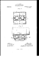
- Fig. 3 is a horizontal section taken on the line 6233 m of Fig. 2, some parts being shown in full.
- the numeral 1 indicates the axle, the numeral 2 the locomotive driving box, and the numeral 3 the bearing brass, which'parts are of standard or any suitable construction.
- the numeral 4 indicates the oil cellar which is secured in the box 2 below the axle 1 in the usual or any suitable manner.
- the oil cellar 4 as shown and as pref erably constructed for locomotive service, has two alined laterally spaced so-called float or main chambers 5 and two front and two rear supplemental or drip chambers 6, All the said chambers, it will be noted, are arranged in pairs, the members of which are separated approximately at the center of the journal.
- the oil in the cellar is indicated by the character y.
- the oil distributors, in the form of cylindrical floats 7 are located one within each of the oil chambers 5 and are immersed in the oil contained in the said chambers and their buoyancy keeps Specification of Letters Patent.
- These rotat" w' floats may be constructed of wood or any 01 iei suitable material and they are preferably provided with trunnion-s 8 that work in vertical guides 9 formed in the sides of the chambers 5.
- the trunnions 8 hold the rotating floats in proper working positions and they are of such diameters, as compared with the diameters of said floats, that the resistance due to their engagement with the walls of the. guides 9 is of a negligible amount.
- the dividing of the oil cellar into compartments is important, especially on long journals such as locomotive or car axle journals.
- long journals such as locomotive or car axle journals.
- the journal box is tipped on an angle great enough to allow the oil to run or spill from a well filled cellar of the types hitherto employed.
- an oil cellar fastened to a twelveinch long journal box passes over a curve which would tip one and one-half inches in its length, and that this cellar has only one compartment.
- the compartments divided longitudinally of the journal as illustrated in the drawings, the level of the oil could be maintained within three-fourths of an inch from the top of the Well without causing spilling of the oil under the conditions above described.
- the longitudinally spaced main oil chambers 5 are preferably in communication with each other through one or more small orifices 10 (see Fig. 2), which permits the oil to slowly run from the one chamber to the other.
- the supplemental chambers 6 are connected to the corresponding main chambers 5 by relatively large oil passages 11.
- supplemental oil chambers are provided, at their upper portions, with overlapped baffle plates 12 which Will also very greatly aid in keeping the oil in the cellars.
Landscapes
- Chemical & Material Sciences (AREA)
- Oil, Petroleum & Natural Gas (AREA)
- Engineering & Computer Science (AREA)
- Mechanical Engineering (AREA)
- Sliding-Contact Bearings (AREA)
Description
APPLICATION FILED MARI], 1910.
Patented Oct. 11, 1910 I. A. RANDEL. JOURNAL LUBHIGATIHG DEVICE.
APPLIOATIOF FILED mum, 1910.
972,719. Patented Oct. 11,1910.
2 SHEETS-$81111! 2.
um .ri'nu D'L'A'l'lnp' erTENT OFFICE.
IVAR A. RANDEL, OF CHICAGO, ILLINOIS, ASSIGNOR TO MGCORD & COMPANY, OF CHICAGO, ILLINOIS, A CORPORATION.
JOUBNAL-LUBRICATING DEVICE.
Application filed March 7,
To (Ill whom it may concern:
Be it known that 1, Ivan A. RANDEL, a citizen of the United States, residing at Chicago, in the county of Cook and State of Illinois, have invented certain new and useful Improvements in Journal-ln1bricating Devices; and l do hereby declare the following to be a full, clear, and exact description of the invention, such as will enable others skilled in the art to which it appertains to make and use the same.
My invention has for its object to provide an improved lubricator adapted for general use in connection with journals, but especially adapted for use on the journals of locomotives and car trucks.
To the above ends, the invention consists of the novel devices and combination of'devices hereinafter described and defined in the claims.
In the accompanying drawings which illustrate the invention, like characters indicate like parts throughout the several news.
Referring to the drawings, Figure l is a view, partly in side elevation and partly in vertical section, illustrating my invention applied to a locomotive driving box; Fig. 2 is a View partly in elevation and partly in section on the line 00 m of Fig. 1, some parts being broken away; and Fig. 3 is a horizontal section taken on the line 6233 m of Fig. 2, some parts being shown in full.
The numeral 1 indicates the axle, the numeral 2 the locomotive driving box, and the numeral 3 the bearing brass, which'parts are of standard or any suitable construction.
The numeral 4 indicates the oil cellar which is secured in the box 2 below the axle 1 in the usual or any suitable manner.
The oil cellar 4, as shown and as pref erably constructed for locomotive service, has two alined laterally spaced so-called float or main chambers 5 and two front and two rear supplemental or drip chambers 6, All the said chambers, it will be noted, are arranged in pairs, the members of which are separated approximately at the center of the journal. The oil in the cellar is indicated by the character y. The oil distributors, in the form of cylindrical floats 7 are located one within each of the oil chambers 5 and are immersed in the oil contained in the said chambers and their buoyancy keeps Specification of Letters Patent.
Patented Oct. 11, 191.0.
1910. Serial No. 547,629.
the upper surfaces thereof pressed against the lower surfaces of the axle 1, so that they will be rotated under frictional engagement therewith, when the axle is rotated. These rotat" w' floats may be constructed of wood or any 01 iei suitable material and they are preferably provided with trunnion-s 8 that work in vertical guides 9 formed in the sides of the chambers 5. The trunnions 8 hold the rotating floats in proper working positions and they are of such diameters, as compared with the diameters of said floats, that the resistance due to their engagement with the walls of the. guides 9 is of a negligible amount. The vertically extended guides Qpermit the rotating floats, by their own buoyancy, to move vertically and thereby compensate for any wear of the brasses 3 or for varying thickness in different brasses which, from time to time, may be used in the box 2.
The dividing of the oil cellar into compartments is important, especially on long journals such as locomotive or car axle journals. When a locomotive or a car passes over a curve, the journal box is tipped on an angle great enough to allow the oil to run or spill from a well filled cellar of the types hitherto employed. To further illustrate, suppose an oil cellar fastened to a twelveinch long journal box passes over a curve which would tip one and one-half inches in its length, and that this cellar has only one compartment. In this instance, to prevent spilling of oil, it would be necessary to keep the oil level one and one-half inches below the top of the box. On the other hand, with the compartments divided longitudinally of the journal, as illustrated in the drawings, the level of the oil could be maintained within three-fourths of an inch from the top of the Well without causing spilling of the oil under the conditions above described.
The longitudinally spaced main oil chambers 5 are preferably in communication with each other through one or more small orifices 10 (see Fig. 2), which permits the oil to slowly run from the one chamber to the other. The supplemental chambers 6 are connected to the corresponding main chambers 5 by relatively large oil passages 11.
In addition to the features of subdividing the oil cellar into a multiplicity of chambers or compartments, the so-called supplemental oil chambers are provided, at their upper portions, with overlapped baffle plates 12 which Will also very greatly aid in keeping the oil in the cellars.
When the axle is rotated, the rotating floats will, as is evident and as stated, also rotate the said floats and the latter will continuously deliver the lubricating oil to the axle. The lubricant will follow the axle and part of it Will be drawn between the axle and bearing brass, While the surplus oil will, under the action of gravity, run down the inner surface of the side Wall of the cellar and thence into the underlying supplemental chambers 6 and from the latter back into the main oil chambers 5. Any sediment, such as iron particles, will be deposited in the supplemental oil chambers and, hence, will not be carried back to the axle journal.
In connection with certain classes of service, such, for example, as train service or boat or automobile service, Where sudden jerks or tipping of the cellar Will be produced, the use of the ballie plates for preventing splashing of the oil is highly desirable, While in stationary service, such bafile plates are not at all necessary.
What I claim is:
1. The combination with an axle and a bearing therefor, of an oil cellar having compartments provided with overlapped bafiie plates, substantially as described.
2. The combination With an axle and a bearing therefor, of an oil cellar having outside and intermediate compartments spaced circumferentially of said axle and having communication at their lower portions, and a rotary oil distributer in the intermediate compartment, in the form of a float immersed in oil contained in the said intermediate compartment and by its own buoyancy held in engagement with the said axle .and arranged to be rotated thereby.
In testimony whereof I affix my signature in presence of two Witnesses.
IVAR A. RANDEL.
Witnesses:
ROBERT D. McNALLY, C. J. COPELAND.
Priority Applications (1)
| Application Number | Priority Date | Filing Date | Title |
|---|---|---|---|
| US54762910A US972719A (en) | 1910-03-07 | 1910-03-07 | Journal-lubricating device. |
Applications Claiming Priority (1)
| Application Number | Priority Date | Filing Date | Title |
|---|---|---|---|
| US54762910A US972719A (en) | 1910-03-07 | 1910-03-07 | Journal-lubricating device. |
Publications (1)
| Publication Number | Publication Date |
|---|---|
| US972719A true US972719A (en) | 1910-10-11 |
Family
ID=3041099
Family Applications (1)
| Application Number | Title | Priority Date | Filing Date |
|---|---|---|---|
| US54762910A Expired - Lifetime US972719A (en) | 1910-03-07 | 1910-03-07 | Journal-lubricating device. |
Country Status (1)
| Country | Link |
|---|---|
| US (1) | US972719A (en) |
-
1910
- 1910-03-07 US US54762910A patent/US972719A/en not_active Expired - Lifetime
Similar Documents
| Publication | Publication Date | Title |
|---|---|---|
| US972719A (en) | Journal-lubricating device. | |
| US2044248A (en) | Lubricating pad | |
| US652089A (en) | Lubricating apparatus. | |
| US689522A (en) | Lubricator for shafting, & c. | |
| US787915A (en) | Lubricator. | |
| US1245586A (en) | Automatic journal-lubricator. | |
| US2159750A (en) | Water drain for journal cellars | |
| US1964547A (en) | Lubricator for axle or shaft bearings | |
| US1709442A (en) | Journal bearing | |
| US1863281A (en) | Car journal lubricator | |
| US982715A (en) | Axle-box and wheel oiler. | |
| US514379A (en) | patten | |
| US993808A (en) | Lubricating journal-box. | |
| US704085A (en) | Car-axle box. | |
| US864002A (en) | Lubricator. | |
| US1384502A (en) | Journal-bearing | |
| US1017295A (en) | Journal-box. | |
| US1472363A (en) | Lubricating device for axle journals | |
| US299321A (en) | Car-axle-lubricating device | |
| US627456A (en) | Thomas w | |
| US801300A (en) | Journal-lubricator. | |
| US1187202A (en) | Lubricating device. | |
| US767745A (en) | Lubricating side bearing for cars. | |
| US1792305A (en) | Journal bearing for railway-car axles | |
| US2081314A (en) | Journal bearing |