US972701A - Lubricator. - Google Patents
Lubricator. Download PDFInfo
- Publication number
- US972701A US972701A US52445209A US1909524452A US972701A US 972701 A US972701 A US 972701A US 52445209 A US52445209 A US 52445209A US 1909524452 A US1909524452 A US 1909524452A US 972701 A US972701 A US 972701A
- Authority
- US
- United States
- Prior art keywords
- valve
- oil
- cylinder
- chamber
- pipe
- Prior art date
- Legal status (The legal status is an assumption and is not a legal conclusion. Google has not performed a legal analysis and makes no representation as to the accuracy of the status listed.)
- Expired - Lifetime
Links
Images

Classifications
-
- B—PERFORMING OPERATIONS; TRANSPORTING
- B61—RAILWAYS
- B61K—AUXILIARY EQUIPMENT SPECIALLY ADAPTED FOR RAILWAYS, NOT OTHERWISE PROVIDED FOR
- B61K3/00—Wetting or lubricating rails or wheel flanges
- B61K3/02—Apparatus therefor combined with vehicles
Definitions
- This invention relates to certain new and useful improvements in lubricators and more particularly to an automatic lubricator adapted to feed the lubricant to the flanges of car wheels to reduce the friction to a minimum upon rounding a curve in the track.
- the primary object of the present invention is to provide a lubricator of the above character which is of simple construction, absolutely positive in its operation and automatically operated by the movement of the train.
- a further object is to. provide a lubricating device comprising a cylinder having an oil chamber and a valve therein adapted to control the flow of lubricant supplied to the outlet, a ball being located in one end of said cylinder and adapted to contact with the valve stem to open the valve.
- FIG. 5 indicates the cylinder which is arranged and supported upon the car in any suitable manner.
- This cylinder is disposed above the drive wheel 6 and as clearly shown in Fig. 3 is formed in two separable sections.
- the section 7 comprises two semi-cylindrical sections which are each formed with a solid end portion 8. The outer end of the solid portions of these sections is threaded and reduced to receive the interiorly threaded end of the other cylinder section 7 The portions 8 are each discharged into the outlet pipe 19.
- a longitudinal groove 10 communicates with the concavity 9 and forms a duct or channel through which the lubricating fluid is adapt ed to flow into the collecting chamber.
- the outer end of this channel is outwardly inclined to form a conical valve seat 11.
- This valve seat is adapted to receive the valve 12 which is normally held therein by the spiral spring 13.
- One end of this spring is dis posed against the end of the valve 12 and around the reduced extension or stud 12 which retains the spring in its proper operative position.
- the other end of the spring is secured to a plate 14 carried upon the inner end of an adjusting screw 15.
- This screw extends centrally through a closure cap 16 threaded upon the ends of the sections of the casing 7.
- the space between the closure cap 16 and the inner end wall of the solid end 8 of the section 7 provides an oil chamber 17 to which the oil is adapted to be fed through the feed pipe 18 co1n1nunieating therewith.
- This feed pipe extends to a suitable tank or reservoir (not shown) adapted to contain the supply of lubricant.
- An outlet pipe 19 is threaded into'the casing 7 and a short passage or channel 20 connects the collecting chamber therewith through which the oil or lubricant is adapted to flow.
- the adjusting screw 15 is adapted to regulate the tension of the spiral spring 13 and may be secured in its adjusted posltlon by a jam nut 21 which engages the closure cap 16.
- the end of the other section 7 of the cylinder is closed by a cap 22 which is provided with a central aperture 23 through which the air escapes from the mterior of the cylinder section 7.
- a ball 24 is disposed and is preferably formed of steel.
- This ball is adapted to contact with the end of the valve stem 25 which is movably disposed through the outer end of the solid portion 8 of the cylinder section 7 and unseats the valve 12 against the tension of the spring 13 allowing the lubricant to pass from the chamber 17 through the conducting passage 10 and into the collecting chamber whence it is
- the lower end of this pipe is connected by a length of flexible tubing 26 to the upper end of a pipe section 27.
- This pipe section has its lower end threaded into the lubricant supply pipe 28.
- This pipe is provided with a central bore 29 the lower end of which is extended at right angles transversely to the pipe as shown at 29.
- the upper end of the oil duct 30 communicates with the outer end of the bore and gradually tapers to the surface of the pipe forming an elongated V- shaped slot.
- the lower end of the pipe 28 adjacent to the bore 29 is provided with an arcuate groove 31 which receives the flange 6 of the car wheel.
- the V-shaped slot extends upon one side of the flange and conducts the lubricating oil thereto from the bore 29.
- the pipe 28 is securely held against the flange of the wheel by means of a heavy leaf spring 32 which is secured in any desired manner to the truck frame of the car.
- the flexible connection 26 between the pipe sections will absorb the vibration which would otherwise be imparted to the device and seriously affect its proper operation.
- the steel ball 24 is positioned in the outer end of the cylinder section 7. As the outer car wheels strike the curve of the track, the flanges of the wheels are placed under very high friction. The lubricant from the chamber 17 is automatically supplied to the flange of the wheel to reduce this friction to a minimum and the valve 12 is automatically actuated at the instant the wheels engage with the curve of the track to feed the lubricant from the cylinder to the supply pipe 28 whence itflows into the slot 30 and upon the wheel flange.
- the device is adapted to be secured to the engine and arranged in a position transverse to the direction of movement.
- One of the lubricators would preferably be mounted upon each side of the engine above the track rails, and the oil chambers positioned inwardly toward the longitudinal center of the engine.
- the oil will be fed to the flanges of the outside wheels which receive the friction occasioned by the movement of the engine upon the curve of the track rails. hen the train leaves the curve the balls 24 will the-n assume their normal inoperative posi: tions, the valve 12 being seated by the spring 13 to cutoff the supply of lubricant,
- the tension of the valve spring 13 may be regulated by adjusting the screw 15 to vary the supply of oil and to absorb the shock to the valve from the violent contact of the ball 2% with the stem when the engine is being driven at high speed.
- the lubricant will be automatically supplied to the wheel flanges only during the time when the train is upon the curve; immediately upon resuming its position upon a level stretch of track, the feed of the lubricant is automatically cut off. Its operation is very positive and the wear upon the wheels will be reduced to a minimum.
- the operation of the lubricator requires no attention beyond the periodical refilling of the supply tank, and as the parts are all of conventional form and may be readily manufactured at a slight cost, it will be obvious that the production of a lubricator constructed as above set forth will be comparatively inexpensive.
- a device of the character described the combination with a cylindrical casing havinga chamber in each end thereof and a central oil receiving chamber between said end chambers, of a spring controlled valve in one of said end chambers, said chamber being adapted to receive lubricating oil, said cylinder having a passage therein connecting the end oil chamber with the central chamber, said valve normally closing said passage, a ball freely movable in the other of the end chambers ada ted to en a e said valve and open the same to admit the oil to the central chamber, and a flexible conducting tube communicating with the last named chamber to convey the oil therefrom to the wheel flange.
- I11 a device of the character described, the combination with a sectional cylinder, one of said sections having an oil chamber therein, of a spring cont-rolled valve disposed in said chamber, a ball movably disposed in the other of the cylinder sections, a solid connecting portion between said sections, said portion having a collecting chamber formed centrally therein, said oil chamber and collecting chamber being connected by an oil passage, said valve having seated engagementin one end of said passage, a supmayor ply pipe Communicating with said oil chamher, and an outlet pipe communicating with the collecting chamber and adapted to convey lubricating oil to a flanged wheel, said valve being automatically opened by the movement of said ball, substantially as and for the purpose set forth.
- a sectional cylinder one of said sections having a solid end provided with a reduced screw threaded portion adapted to be engaged in the interiorly threaded end of the other section of the cylinder
- said first named section comprising two separable semi-cylindrical portions, the solid ends thereof each having a central concavity adapted to form a collecting chamher when the portions are united, with a closure cap threaded upon the outer end of said section to provide an oil chamber therein, a supply pipe communicating with said oil chamber, the solid portion of said section having a passage therein connecting the oil chamber with the collecting chamber, one end of said passage being enlarged to form a conical valve seat, a valve normally closing said passage, a spring in the oil cham ber normally adapted to retain the valve in its seat, a valve stem integrally formed in the valve extending through the solid end portion of the cylinder section, a feed pipe communicating with the collecting chamber, and a ball movably disposed in the other section
- a cylinder having an oil chamber in one end thereof, said cylinder being formed with an intermediate solid portion, said solid portion being provided with a central spherical collecting chamber, and a communicating passage between the oil chamber and collecting chamber, one end of said passage being enlarged to provide a conical valve seat, with a valve member normally disposed in said seat, a spiral spring centrally arranged in the oil chamber acting to retain the valve in its normal position, an adjusting screw threaded through the end of said cylinder adapted to regulate the tension of said spring, a supply pipe communicating with the oil chamber, a feed pipe threaded into the solid portion of the cylinder and communicating with the collecting chamber, a valve stem integrally formed with said valve extending through the solid portion of the cylinder, and a ball movable upon the opposite side of the solid portion adapted to engage with the valve stem and open the valve, substantially as and for the purpose set forth.
- a device of the class described the combination of a cylinder, closure caps threaded upon the opposite ends of said eyl inder, said cylinder having an intermediate solid portion provided with a central collecting chamber, the interior of said cylinder upon one side of said solid portion forming an oil chamber, with a ball movable 1n the opposite tubular portion of the cylinder, said solid portion having a communicating passage between the oil chamber and the collecting chamber, one end of said passage being outwardly flared to form a conical valve seat, a cylindrical valve member having a conical end portion normally disposed in said seat, a valve stem integrally formed with said member extending through the solid portion of said cylinder, an ad ust1ng screw extending into the oil chamber and having threaded engagement in the closure cap, a spiral spring secured at one end to said screw and engaging said valve member to normally retain the same in engagement with its seat, a feed pipe threaded into the solid portion of said cylinder and connected to the collecting chamber by a commumcating passage, said feed pipe comp
- a device of the class described the combination of a cylinder having an oil chamber in one end thereof and an intermediate solid portion, an oil passage extending through said solid portion, with a valve normally seated in said passage, a valve stem integrally formed with the valve extending longitudinally through the solid portion of said cylinder, removable closure caps on the ends of said cylinder, an adjusting screw threaded through one of said caps and extending into the oil chamber, a spiral spring secured to the inner end of said screw and bearing against said valve to retain the same in its seat, said valve having a reduced extension on one end extending into said spring, a ball movable in the other end of said cylinder adapted to engage with the valve stem and unseat the valve, a supply pipe con'imunicating with the oil chamber, an outlet pipe adapted to receive oil from the oil chamber, said outlet pipe comprising two sections connected by a flexible tube, and an oil conducting member threaded on the lower end of said pipe having a central longitudinal bore, and an arcuate groove in the lower end of said member adapted to
- a device of the class described the combination of a cylinder having a central wall therein forming a chamber in each of its ends, one ofsaid chambers being adapted to receive a supply of lubricating oil and having an oil outlet, a spring controlled valve in said oil chamber normally closing 1 the outlet, means for adjusting the tension of the valve spring to return the valve to its seat, the stem of said valve normally extending through the central wall of the cylinder, a ball longitudinally movable in the other chamber of said cylinder adapted to engage the valve stem and open said valve against the tension of the spring and a conducting pipe connected to the outlet of the oil chamber and adapted to receive the oil therefrom to convey the same to a wheel flange.
- a device of the character described the combination with a cylinder having an oil chamber in one end thereof, a supply pipe communicating with said chamber, a feed pipe having threaded engagement in the cylinder and connected to the oil chamber by an outlet passage, a valve normally closing said outlet, a spring adapted to resiliently retain the valve in its seat, means for regulating the tension of said spring, a ball movable in said cylinder adapted to be moved at certain times into engagement with the stem of the valve to open the same, said feed pipe comprising two'spaced sections, and a flexible connection between said sections, an oil conducting member threaded upon the lower end of the feed pipe having a central bore terminating intermediate of its ends, the end of said bore being extended at right angles to the surface of said member, said member having an arcuate groove therein adapted to receive the flange of a wheel and a longitudinally extending V- shaped slot communicating with the angular end of the bore adapted to supply the lubricant to the wheel flange, and a leaf spring disposed against
- a lubricator comprising a cylindrical casing formed in two detachable sections, a valve carried by one of said sections and disposed in an oil chamber formed therein, a ball movably disposed in the other of said sections, means adjustably carried by the first named section normally acting to yieldingly hold said valve closed, said casing section having a collecting chamber formed therein communicating with the valve chamber, said ball being adapted to engage with and automatically open said valve at certain times to permit the flow of the oil from said oil chamber into said collecting chamber, and means for withdrawing the oil from said collecting chamber.
Description
L. J. MALOY.
LUBRIGATOR. APPLIOATION FILED 001'. 25, 1909.
Patented Oct. 11,1910.
2 SHEETS-BHBB'I'L L. ALOY.
' L Aaron, P PPPPPPPPPPPPPPPPPPPPPPPPP 9.
EEEEEEEEEEEEE 2.
.IIIIAV B L] l H i Imam Q if Urn star 1 A FFC.
LEWIS JACKSON MALOY, OF COPPERHILL, TENNESSEE.
LUBRICATOR.
Specification of Letters Patent.
Application filed October 25, 1909.
To all whom it may concern:
Be it known that I, LnwIs JACKSON MA- LoY, a citizen of the United States, residing at Copperhill, in the county of Polk and State of Tennessee, have invented certain new and useful Improvements in Lubri cators, of which the following is a specification, reference being had to the accompanying drawings.
This invention relates to certain new and useful improvements in lubricators and more particularly to an automatic lubricator adapted to feed the lubricant to the flanges of car wheels to reduce the friction to a minimum upon rounding a curve in the track.
The primary object of the present invention is to provide a lubricator of the above character which is of simple construction, absolutely positive in its operation and automatically operated by the movement of the train.
A further object is to. provide a lubricating device comprisinga cylinder having an oil chamber and a valve therein adapted to control the flow of lubricant supplied to the outlet, a ball being located in one end of said cylinder and adapted to contact with the valve stem to open the valve.
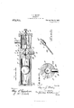
With these and other objects in view, the invention consists of the novel construction, combination and arrangement of parts hereinafter fully described and claimed, and illustrated in the accompanying drawings, in which- Figure l is a side elevation of my improved lubricator showing the same arranged in operative relation to the wheel flange; Fig. 2 is a vertical section through the flange engaging oil conducting member; Fig. 3 is a longitudinal section through the lubricator; Fig. 4 is a transverse section taken on the line 44 of Fig. 3; and Fig. 5 is a detail perspective view of the valve.
Referring to the drawings 5 indicates the cylinder which is arranged and supported upon the car in any suitable manner. This cylinder is disposed above the drive wheel 6 and as clearly shown in Fig. 3 is formed in two separable sections. The section 7 comprises two semi-cylindrical sections which are each formed with a solid end portion 8. The outer end of the solid portions of these sections is threaded and reduced to receive the interiorly threaded end of the other cylinder section 7 The portions 8 are each discharged into the outlet pipe 19.
provided with a central semi-spherical concavity 9, which when the sections are disposed upon each other and connected forms a central spherical collecting chamber. A longitudinal groove 10 communicates with the concavity 9 and forms a duct or channel through which the lubricating fluid is adapt ed to flow into the collecting chamber. The outer end of this channel is outwardly inclined to form a conical valve seat 11. This valve seat is adapted to receive the valve 12 which is normally held therein by the spiral spring 13. One end of this spring is dis posed against the end of the valve 12 and around the reduced extension or stud 12 which retains the spring in its proper operative position. The other end of the spring is secured to a plate 14 carried upon the inner end of an adjusting screw 15. This screw extends centrally through a closure cap 16 threaded upon the ends of the sections of the casing 7. The space between the closure cap 16 and the inner end wall of the solid end 8 of the section 7 provides an oil chamber 17 to which the oil is adapted to be fed through the feed pipe 18 co1n1nunieating therewith. This feed pipe extends to a suitable tank or reservoir (not shown) adapted to contain the supply of lubricant. An outlet pipe 19 is threaded into'the casing 7 and a short passage or channel 20 connects the collecting chamber therewith through which the oil or lubricant is adapted to flow. The adjusting screw 15 is adapted to regulate the tension of the spiral spring 13 and may be secured in its adjusted posltlon by a jam nut 21 which engages the closure cap 16. The end of the other section 7 of the cylinder is closed by a cap 22 which is provided with a central aperture 23 through which the air escapes from the mterior of the cylinder section 7. Within the cylinder 7 a ball 24: is disposed and is preferably formed of steel. This ball is adapted to contact with the end of the valve stem 25 which is movably disposed through the outer end of the solid portion 8 of the cylinder section 7 and unseats the valve 12 against the tension of the spring 13 allowing the lubricant to pass from the chamber 17 through the conducting passage 10 and into the collecting chamber whence it is The lower end of this pipe is connected by a length of flexible tubing 26 to the upper end of a pipe section 27. This pipe section has its lower end threaded into the lubricant supply pipe 28. This pipe is provided with a central bore 29 the lower end of which is extended at right angles transversely to the pipe as shown at 29. The upper end of the oil duct 30 communicates with the outer end of the bore and gradually tapers to the surface of the pipe forming an elongated V- shaped slot. The lower end of the pipe 28 adjacent to the bore 29 is provided with an arcuate groove 31 which receives the flange 6 of the car wheel. The V-shaped slot extends upon one side of the flange and conducts the lubricating oil thereto from the bore 29. The pipe 28 is securely held against the flange of the wheel by means of a heavy leaf spring 32 which is secured in any desired manner to the truck frame of the car. The flexible connection 26 between the pipe sections will absorb the vibration which would otherwise be imparted to the device and seriously affect its proper operation.
Normally the steel ball 24 is positioned in the outer end of the cylinder section 7. As the outer car wheels strike the curve of the track, the flanges of the wheels are placed under very high friction. The lubricant from the chamber 17 is automatically supplied to the flange of the wheel to reduce this friction to a minimum and the valve 12 is automatically actuated at the instant the wheels engage with the curve of the track to feed the lubricant from the cylinder to the supply pipe 28 whence itflows into the slot 30 and upon the wheel flange.
In the operation of my improved lubricator, the device is adapted to be secured to the engine and arranged in a position transverse to the direction of movement. One of the lubricators would preferably be mounted upon each side of the engine above the track rails, and the oil chambers positioned inwardly toward the longitudinal center of the engine. By such an arrangement it will be obvious that when the wheel flanges strike the curve of the track rails owing to the fact that the outer rail is banked above the horizontal plane of the inner rail, the ball 24 arranged in the casing adjacent to the outside rail will move inwardly as the trucks are transversely inclined and engage with the valve stem, thereby opening the valve against the tension of the spring 13 and allowing the free passage of the oil in the chamber 17 into the outlet pipe 19 whence it is conducted to the wheel flange. The ball 24 of the other lubricating device arranged above the inside track rail will move to the outer end of its casing away from the valve stem. Thus the oil will be fed to the flanges of the outside wheels which receive the friction occasioned by the movement of the engine upon the curve of the track rails. hen the train leaves the curve the balls 24 will the-n assume their normal inoperative posi: tions, the valve 12 being seated by the spring 13 to cutoff the supply of lubricant, The tension of the valve spring 13 may be regulated by adjusting the screw 15 to vary the supply of oil and to absorb the shock to the valve from the violent contact of the ball 2% with the stem when the engine is being driven at high speed.
From the foregoing it will be seen that the lubricant will be automatically supplied to the wheel flanges only during the time when the train is upon the curve; immediately upon resuming its position upon a level stretch of track, the feed of the lubricant is automatically cut off. Its operation is very positive and the wear upon the wheels will be reduced to a minimum. The operation of the lubricator requires no attention beyond the periodical refilling of the supply tank, and as the parts are all of conventional form and may be readily manufactured at a slight cost, it will be obvious that the production of a lubricator constructed as above set forth will be comparatively inexpensive. IVhile I have shown and described what I believe to be the preferable embodiment of my invention, I do not wish to be limited to the eX- act details of construction as set forth as numerous minor modifications may be resorted to within the scope of the claims without departing from the essential features or sacrificing any of the advantages of the invention.
Having thus described the invention, what is claimed is:
1. In a device of the character described the combination with a cylindrical casing havinga chamber in each end thereof and a central oil receiving chamber between said end chambers, of a spring controlled valve in one of said end chambers, said chamber being adapted to receive lubricating oil, said cylinder having a passage therein connecting the end oil chamber with the central chamber, said valve normally closing said passage, a ball freely movable in the other of the end chambers ada ted to en a e said valve and open the same to admit the oil to the central chamber, and a flexible conducting tube communicating with the last named chamber to convey the oil therefrom to the wheel flange.
2. I11 a device of the character described, the combination with a sectional cylinder, one of said sections having an oil chamber therein, of a spring cont-rolled valve disposed in said chamber, a ball movably disposed in the other of the cylinder sections, a solid connecting portion between said sections, said portion having a collecting chamber formed centrally therein, said oil chamber and collecting chamber being connected by an oil passage, said valve having seated engagementin one end of said passage, a supmayor ply pipe Communicating with said oil chamher, and an outlet pipe communicating with the collecting chamber and adapted to convey lubricating oil to a flanged wheel, said valve being automatically opened by the movement of said ball, substantially as and for the purpose set forth. I
3. In a device of the character described, the combination of a sectional cylinder, one of said sections having a solid end provided with a reduced screw threaded portion adapted to be engaged in the interiorly threaded end of the other section of the cylinder, said first named section comprising two separable semi-cylindrical portions, the solid ends thereof each having a central concavity adapted to form a collecting chamher when the portions are united, with a closure cap threaded upon the outer end of said section to provide an oil chamber therein, a supply pipe communicating with said oil chamber, the solid portion of said section having a passage therein connecting the oil chamber with the collecting chamber, one end of said passage being enlarged to form a conical valve seat, a valve normally closing said passage, a spring in the oil cham ber normally adapted to retain the valve in its seat, a valve stem integrally formed in the valve extending through the solid end portion of the cylinder section, a feed pipe communicating with the collecting chamber, and a ball movably disposed in the other section of said cylinder adapted to engage the end of the valve stem and unseat the valve, substantially as and for the purpose set forth.
t. In a device of the character described, the combination of a cylinder having an oil chamber in one end thereof, said cylinder being formed with an intermediate solid portion, said solid portion being provided with a central spherical collecting chamber, and a communicating passage between the oil chamber and collecting chamber, one end of said passage being enlarged to provide a conical valve seat, with a valve member normally disposed in said seat, a spiral spring centrally arranged in the oil chamber acting to retain the valve in its normal position, an adjusting screw threaded through the end of said cylinder adapted to regulate the tension of said spring, a supply pipe communicating with the oil chamber, a feed pipe threaded into the solid portion of the cylinder and communicating with the collecting chamber, a valve stem integrally formed with said valve extending through the solid portion of the cylinder, and a ball movable upon the opposite side of the solid portion adapted to engage with the valve stem and open the valve, substantially as and for the purpose set forth.
In a device of the class described, the combination of a cylinder, closure caps threaded upon the opposite ends of said eyl inder, said cylinder having an intermediate solid portion provided with a central collecting chamber, the interior of said cylinder upon one side of said solid portion forming an oil chamber, with a ball movable 1n the opposite tubular portion of the cylinder, said solid portion having a communicating passage between the oil chamber and the collecting chamber, one end of said passage being outwardly flared to form a conical valve seat, a cylindrical valve member having a conical end portion normally disposed in said seat, a valve stem integrally formed with said member extending through the solid portion of said cylinder, an ad ust1ng screw extending into the oil chamber and having threaded engagement in the closure cap, a spiral spring secured at one end to said screw and engaging said valve member to normally retain the same in engagement with its seat, a feed pipe threaded into the solid portion of said cylinder and connected to the collecting chamber by a commumcating passage, said feed pipe comprlsmg two sections connected by a flexible tube. and an oil conducting member threaded on the lower end of the feed pipe adapted to engage with the flange of a wheel to supply the lubricating oil thereto upon the movement of said ball into engagement with the valve stem, substantially as and for the purpose set forth.
6. In a device of the class described, the combination of a cylinder having an oil chamber in one end thereof and an intermediate solid portion, an oil passage extending through said solid portion, with a valve normally seated in said passage, a valve stem integrally formed with the valve extending longitudinally through the solid portion of said cylinder, removable closure caps on the ends of said cylinder, an adjusting screw threaded through one of said caps and extending into the oil chamber, a spiral spring secured to the inner end of said screw and bearing against said valve to retain the same in its seat, said valve having a reduced extension on one end extending into said spring, a ball movable in the other end of said cylinder adapted to engage with the valve stem and unseat the valve, a supply pipe con'imunicating with the oil chamber, an outlet pipe adapted to receive oil from the oil chamber, said outlet pipe comprising two sections connected by a flexible tube, and an oil conducting member threaded on the lower end of said pipe having a central longitudinal bore, and an arcuate groove in the lower end of said member adapted to receive the flange of a wheel, substantially as and for the purpose set forth. I
7. In a device of the class described the combination of a cylinder having a central wall therein forming a chamber in each of its ends, one ofsaid chambers being adapted to receive a supply of lubricating oil and having an oil outlet, a spring controlled valve in said oil chamber normally closing 1 the outlet, means for adjusting the tension of the valve spring to return the valve to its seat, the stem of said valve normally extending through the central wall of the cylinder, a ball longitudinally movable in the other chamber of said cylinder adapted to engage the valve stem and open said valve against the tension of the spring and a conducting pipe connected to the outlet of the oil chamber and adapted to receive the oil therefrom to convey the same to a wheel flange.
8. In a device of the character described, the combination with a cylinder having an oil chamber in one end thereof, a supply pipe communicating with said chamber, a feed pipe having threaded engagement in the cylinder and connected to the oil chamber by an outlet passage, a valve normally closing said outlet, a spring adapted to resiliently retain the valve in its seat, means for regulating the tension of said spring, a ball movable in said cylinder adapted to be moved at certain times into engagement with the stem of the valve to open the same, said feed pipe comprising two'spaced sections, and a flexible connection between said sections, an oil conducting member threaded upon the lower end of the feed pipe having a central bore terminating intermediate of its ends, the end of said bore being extended at right angles to the surface of said member, said member having an arcuate groove therein adapted to receive the flange of a wheel and a longitudinally extending V- shaped slot communicating with the angular end of the bore adapted to supply the lubricant to the wheel flange, and a leaf spring disposed against said conduct-ing member and adapted to retain the same in yielding engagement with the wheel flange, substantially as and for the purpose set forth.
9. A lubricator comprising a cylindrical casing formed in two detachable sections, a valve carried by one of said sections and disposed in an oil chamber formed therein, a ball movably disposed in the other of said sections, means adjustably carried by the first named section normally acting to yieldingly hold said valve closed, said casing section having a collecting chamber formed therein communicating with the valve chamber, said ball being adapted to engage with and automatically open said valve at certain times to permit the flow of the oil from said oil chamber into said collecting chamber, and means for withdrawing the oil from said collecting chamber.
In testimony whereof I hereunto affix my signature in the presence of two witnesses.
LEWVIS J AOKSON MALOY.
Vitnesses GEO. T. HOOD, Y. GILLIAM'.
Priority Applications (1)
| Application Number | Priority Date | Filing Date | Title |
|---|---|---|---|
| US52445209A US972701A (en) | 1909-10-25 | 1909-10-25 | Lubricator. |
Applications Claiming Priority (1)
| Application Number | Priority Date | Filing Date | Title |
|---|---|---|---|
| US52445209A US972701A (en) | 1909-10-25 | 1909-10-25 | Lubricator. |
Publications (1)
| Publication Number | Publication Date |
|---|---|
| US972701A true US972701A (en) | 1910-10-11 |
Family
ID=3041081
Family Applications (1)
| Application Number | Title | Priority Date | Filing Date |
|---|---|---|---|
| US52445209A Expired - Lifetime US972701A (en) | 1909-10-25 | 1909-10-25 | Lubricator. |
Country Status (1)
| Country | Link |
|---|---|
| US (1) | US972701A (en) |
-
1909
- 1909-10-25 US US52445209A patent/US972701A/en not_active Expired - Lifetime
Similar Documents
| Publication | Publication Date | Title |
|---|---|---|
| US972701A (en) | Lubricator. | |
| US651381A (en) | Lubricator. | |
| US2306013A (en) | Flange lubricator | |
| US1497177A (en) | Track lubricator | |
| US791640A (en) | Lubricating device. | |
| US777428A (en) | Device for lubricating wheel-flanges. | |
| US383558A (en) | Lubricating attachment for railway-cars | |
| US1315487A (en) | James w | |
| US981597A (en) | Automatic flange-oiler. | |
| US1213676A (en) | Wheel-flange lubricator. | |
| US1081419A (en) | Lubricant-distributer. | |
| US1596281A (en) | Automatic feeding device for track or flange oilers | |
| US713910A (en) | Sand-valve mechanism. | |
| US1786334A (en) | Lubricating apparatus for the flanges of wheels of engines or vehicles traveling upon railway tracks | |
| US459129A (en) | Oil-cup attachment for journal-boxes | |
| US1234585A (en) | Automatic oiler or lubricator. | |
| US1004006A (en) | Rail-lubricator. | |
| US1143681A (en) | Automatic flange-lubricator. | |
| US1278596A (en) | Auto-rail-lubricator. | |
| US772153A (en) | Lubricating device. | |
| US974222A (en) | Lubricator. | |
| US497273A (en) | Albert a | |
| US152878A (en) | Improvement in switch-attachments for street-cars | |
| US143830A (en) | Improvement i | |
| US776188A (en) | Lubricator. |