US9720176B2 - Low-loss high-repetition-rate pulsed laser modulator - Google Patents
Low-loss high-repetition-rate pulsed laser modulator Download PDFInfo
- Publication number
- US9720176B2 US9720176B2 US15/001,244 US201615001244A US9720176B2 US 9720176 B2 US9720176 B2 US 9720176B2 US 201615001244 A US201615001244 A US 201615001244A US 9720176 B2 US9720176 B2 US 9720176B2
- Authority
- US
- United States
- Prior art keywords
- coupler
- repetition
- light
- pulsed laser
- rate
- Prior art date
- Legal status (The legal status is an assumption and is not a legal conclusion. Google has not performed a legal analysis and makes no representation as to the accuracy of the status listed.)
- Active
Links
- 239000000835 fiber Substances 0.000 claims description 18
- 230000003287 optical effect Effects 0.000 abstract description 6
- 238000000034 method Methods 0.000 description 3
- 230000008878 coupling Effects 0.000 description 1
- 238000010168 coupling process Methods 0.000 description 1
- 238000005859 coupling reaction Methods 0.000 description 1
- 238000005516 engineering process Methods 0.000 description 1
- 238000005259 measurement Methods 0.000 description 1
- 238000001208 nuclear magnetic resonance pulse sequence Methods 0.000 description 1
- 238000005070 sampling Methods 0.000 description 1
Images

Classifications
-
- H—ELECTRICITY
- H01—ELECTRIC ELEMENTS
- H01S—DEVICES USING THE PROCESS OF LIGHT AMPLIFICATION BY STIMULATED EMISSION OF RADIATION [LASER] TO AMPLIFY OR GENERATE LIGHT; DEVICES USING STIMULATED EMISSION OF ELECTROMAGNETIC RADIATION IN WAVE RANGES OTHER THAN OPTICAL
- H01S3/00—Lasers, i.e. devices using stimulated emission of electromagnetic radiation in the infrared, visible or ultraviolet wave range
- H01S3/10—Controlling the intensity, frequency, phase, polarisation or direction of the emitted radiation, e.g. switching, gating, modulating or demodulating
- H01S3/101—Lasers provided with means to change the location from which, or the direction in which, laser radiation is emitted
-
- G—PHYSICS
- G02—OPTICS
- G02B—OPTICAL ELEMENTS, SYSTEMS OR APPARATUS
- G02B6/00—Light guides; Structural details of arrangements comprising light guides and other optical elements, e.g. couplings
- G02B6/24—Coupling light guides
- G02B6/26—Optical coupling means
- G02B6/28—Optical coupling means having data bus means, i.e. plural waveguides interconnected and providing an inherently bidirectional system by mixing and splitting signals
- G02B6/2804—Optical coupling means having data bus means, i.e. plural waveguides interconnected and providing an inherently bidirectional system by mixing and splitting signals forming multipart couplers without wavelength selective elements, e.g. "T" couplers, star couplers
- G02B6/2861—Optical coupling means having data bus means, i.e. plural waveguides interconnected and providing an inherently bidirectional system by mixing and splitting signals forming multipart couplers without wavelength selective elements, e.g. "T" couplers, star couplers using fibre optic delay lines and optical elements associated with them, e.g. for use in signal processing, e.g. filtering
-
- H—ELECTRICITY
- H01—ELECTRIC ELEMENTS
- H01S—DEVICES USING THE PROCESS OF LIGHT AMPLIFICATION BY STIMULATED EMISSION OF RADIATION [LASER] TO AMPLIFY OR GENERATE LIGHT; DEVICES USING STIMULATED EMISSION OF ELECTROMAGNETIC RADIATION IN WAVE RANGES OTHER THAN OPTICAL
- H01S3/00—Lasers, i.e. devices using stimulated emission of electromagnetic radiation in the infrared, visible or ultraviolet wave range
- H01S3/05—Construction or shape of optical resonators; Accommodation of active medium therein; Shape of active medium
- H01S3/06—Construction or shape of active medium
- H01S3/063—Waveguide lasers, i.e. whereby the dimensions of the waveguide are of the order of the light wavelength
- H01S3/067—Fibre lasers
-
- H—ELECTRICITY
- H01—ELECTRIC ELEMENTS
- H01S—DEVICES USING THE PROCESS OF LIGHT AMPLIFICATION BY STIMULATED EMISSION OF RADIATION [LASER] TO AMPLIFY OR GENERATE LIGHT; DEVICES USING STIMULATED EMISSION OF ELECTROMAGNETIC RADIATION IN WAVE RANGES OTHER THAN OPTICAL
- H01S3/00—Lasers, i.e. devices using stimulated emission of electromagnetic radiation in the infrared, visible or ultraviolet wave range
- H01S3/10—Controlling the intensity, frequency, phase, polarisation or direction of the emitted radiation, e.g. switching, gating, modulating or demodulating
- H01S3/11—Mode locking; Q-switching; Other giant-pulse techniques, e.g. cavity dumping
-
- G—PHYSICS
- G02—OPTICS
- G02B—OPTICAL ELEMENTS, SYSTEMS OR APPARATUS
- G02B6/00—Light guides; Structural details of arrangements comprising light guides and other optical elements, e.g. couplings
- G02B6/24—Coupling light guides
- G02B6/26—Optical coupling means
- G02B6/28—Optical coupling means having data bus means, i.e. plural waveguides interconnected and providing an inherently bidirectional system by mixing and splitting signals
- G02B6/2804—Optical coupling means having data bus means, i.e. plural waveguides interconnected and providing an inherently bidirectional system by mixing and splitting signals forming multipart couplers without wavelength selective elements, e.g. "T" couplers, star couplers
-
- G—PHYSICS
- G02—OPTICS
- G02F—OPTICAL DEVICES OR ARRANGEMENTS FOR THE CONTROL OF LIGHT BY MODIFICATION OF THE OPTICAL PROPERTIES OF THE MEDIA OF THE ELEMENTS INVOLVED THEREIN; NON-LINEAR OPTICS; FREQUENCY-CHANGING OF LIGHT; OPTICAL LOGIC ELEMENTS; OPTICAL ANALOGUE/DIGITAL CONVERTERS
- G02F1/00—Devices or arrangements for the control of the intensity, colour, phase, polarisation or direction of light arriving from an independent light source, e.g. switching, gating or modulating; Non-linear optics
- G02F1/01—Devices or arrangements for the control of the intensity, colour, phase, polarisation or direction of light arriving from an independent light source, e.g. switching, gating or modulating; Non-linear optics for the control of the intensity, phase, polarisation or colour
- G02F1/011—Devices or arrangements for the control of the intensity, colour, phase, polarisation or direction of light arriving from an independent light source, e.g. switching, gating or modulating; Non-linear optics for the control of the intensity, phase, polarisation or colour in optical waveguides, not otherwise provided for in this subclass
-
- G—PHYSICS
- G02—OPTICS
- G02F—OPTICAL DEVICES OR ARRANGEMENTS FOR THE CONTROL OF LIGHT BY MODIFICATION OF THE OPTICAL PROPERTIES OF THE MEDIA OF THE ELEMENTS INVOLVED THEREIN; NON-LINEAR OPTICS; FREQUENCY-CHANGING OF LIGHT; OPTICAL LOGIC ELEMENTS; OPTICAL ANALOGUE/DIGITAL CONVERTERS
- G02F2201/00—Constructional arrangements not provided for in groups G02F1/00 - G02F7/00
- G02F2201/20—Constructional arrangements not provided for in groups G02F1/00 - G02F7/00 delay line
-
- G—PHYSICS
- G02—OPTICS
- G02F—OPTICAL DEVICES OR ARRANGEMENTS FOR THE CONTROL OF LIGHT BY MODIFICATION OF THE OPTICAL PROPERTIES OF THE MEDIA OF THE ELEMENTS INVOLVED THEREIN; NON-LINEAR OPTICS; FREQUENCY-CHANGING OF LIGHT; OPTICAL LOGIC ELEMENTS; OPTICAL ANALOGUE/DIGITAL CONVERTERS
- G02F2203/00—Function characteristic
- G02F2203/54—Optical pulse train (comb) synthesizer
-
- H—ELECTRICITY
- H01—ELECTRIC ELEMENTS
- H01S—DEVICES USING THE PROCESS OF LIGHT AMPLIFICATION BY STIMULATED EMISSION OF RADIATION [LASER] TO AMPLIFY OR GENERATE LIGHT; DEVICES USING STIMULATED EMISSION OF ELECTROMAGNETIC RADIATION IN WAVE RANGES OTHER THAN OPTICAL
- H01S3/00—Lasers, i.e. devices using stimulated emission of electromagnetic radiation in the infrared, visible or ultraviolet wave range
- H01S3/005—Optical devices external to the laser cavity, specially adapted for lasers, e.g. for homogenisation of the beam or for manipulating laser pulses, e.g. pulse shaping
- H01S3/0085—Modulating the output, i.e. the laser beam is modulated outside the laser cavity
Definitions
- the present invention relates to a technical field of pulsed modulators, and the low-loss high-repetition-rate pulsed laser modulator belongs to the fiber and laser technology.
- pulsed lasers with high repetition rate have been widely used in many fields, such as optical frequency measurement, high-speed electro-optic sampling, laser ranging, and high-average-power ultrafast lasers. Therefore, it has important application values.
- the conventional fiber lasers it is easier to realize a pulse sequence from kHz to hundreds of MHz.
- the fiber lasers are limited to its gain fiber length, other inner devices and the length of tail fiber, it is difficult to increase the repetition rate.
- This invention puts forward a novel method to increase pulsed laser repetition rate by using a 2*2 type, splitting ratio 1:1 coupler (hereinafter written as 2*2, 1:1 coupler) and controlling the optical path difference to realize a low-loss mutual coupling of laser pulses.
- the purpose of the present invention is to provide a low-loss high-repetition pulsed laser modulator with simple devices, a compact structure and novel combination.
- the present invention provides a low-loss high-repetition pulsed laser modulator, including: two 1*2 type, splitting ratio 1:1 (hereinafter written as 1*2, 1:1 coupler), N 2*2, 11 couplers, and N light delay modules. It is characterized in that a beam of pulsed laser is divided into two beams with the same light intensity utilized by a 1*2, 1:1 coupler, and then the two beams of light are coupled together into a 2*2, 1:1 coupler, from which the light is divided into two beams again with the same light intensity, meanwhile, pulses with double quantities and the same period are obtained by changing the optical path difference between the 1*2, 1:1 coupler and the 2*2, 1:1 coupler. Thus the repetition rate can be amplified.
- the low-loss high-repetition-rate pulsed laser modulator is described above. It is characterized in that a light delay module is utilized.
- the basic principle is to compute the period t between the two neighboring pulses according to the pulse repetition rate f. Then the fiber length difference ⁇ l, which is 1/n the optical path difference between the two beams of light propagate before coupled together into a 2*2, 1:1 coupler, can be calculated by the formula,
- ⁇ ⁇ ⁇ l ( kl + t 2 ) ⁇ c n , where, c is the light speed in vacuum, n is refractive index of the fiber core, k is natural number.
- the advantage of this invention is it provides a low-loss high-repetition pulsed laser modulator with simple devices, a compact structure and novel combination.
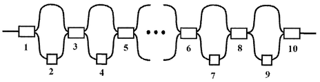
- FIG. 1 illustrates an embodiment of the high-repetition-rate pulsed laser modulator according the present invention, wherein: 1 : 1*2, 1:1 coupler; 2 : light delay module; 3 : 2*2, 1:1 coupler; 4 : light delay module; 5 : 2*2, 1:1 coupler; 6 : 2*2, 1:1 coupler; 7 : light delay module; 8 : 2*2, 1:1 coupler; 9 : light delay module; 10 : 1*2, 1:1 coupler.
- the high-repetition-rate pulsed, laser modulator includes two 1*2, 1:1 couplers ( 1 and 10 ), N 2*2, 1:1 couplers ( 3 , 5 , 6 , 8 and so on), and N light delay modules ( 2 , 4 , 7 , 9 and so on), wherein one beam of pulsed laser whereof repetition rate is f can be divided into two beams with the same light intensity by a 1*2, 1:1 coupler 1 ; one beam of light passes through a fiber having a fiber length difference ⁇ l compared with another, and a light delay module 2 used for modifying the fiber length difference ⁇ l, then the two beams of light are coupled together into a 2*2, 1:1 coupler 3 , the repetition rate of the output light now is 2f, In the same way, one beam of pulsed laser after 2*2, 1:1 coupler 3 , passes through a fiber length difference ⁇ l and a light delay module 4 , and then the two beams of light are coupled together into a 2
- the present invention described above just includes 3 kinds of devices: a 1*2, 1:1 coupler, a light delay module and a 2*2, 1:1 coupler, so it has simple devices, a compact structure and novel combination.
Landscapes
- Physics & Mathematics (AREA)
- Optics & Photonics (AREA)
- Electromagnetism (AREA)
- Engineering & Computer Science (AREA)
- General Physics & Mathematics (AREA)
- Plasma & Fusion (AREA)
- Nonlinear Science (AREA)
- Signal Processing (AREA)
- Theoretical Computer Science (AREA)
- Lasers (AREA)
- Optical Modulation, Optical Deflection, Nonlinear Optics, Optical Demodulation, Optical Logic Elements (AREA)
Abstract
The present invention provides a low-loss high-repetition-rate pulsed laser modulator comprising: a 2*2, 1:1 coupler; a light delay module; a 1*2, 1:1 coupler. The present invention can modulate a low-repetition-rate pulsed laser to be a high-repetition-rate pulsed laser. The basic principle is: one beam of low-repetition-rate pulsed laser can be divided into two beams with the same light intensity by a 1*2, 1:1 coupler; control the two beams of light to have an optical path difference so that when they are coupled into a 2*2, 1:1 coupler, a double pulse repetition rate can be obtained; In the same way, when the two beams of light from former 2*2, 1:1 coupler, with another different optical path difference are coupled into the next 2*2, 1:1 coupler, a double pulse repetition rate can be obtained again; when we obtain the repetition rate we need, a 1*2, 1:1 coupler instead is connected to couple the two beams of light into one beam with a double repetition rate.
Description
This application is a continuation of, and claims priority to, Chinese Patent Application No. 201510853580.3 with a filing date of Dec. 1, 2015. The content of the aforementioned application, including any intervening amendments thereto, is incorporated herein by reference.
The present invention relates to a technical field of pulsed modulators, and the low-loss high-repetition-rate pulsed laser modulator belongs to the fiber and laser technology.
In recent years, pulsed lasers with high repetition rate have been widely used in many fields, such as optical frequency measurement, high-speed electro-optic sampling, laser ranging, and high-average-power ultrafast lasers. Therefore, it has important application values. For the conventional fiber lasers, it is easier to realize a pulse sequence from kHz to hundreds of MHz. However, for the reason the fiber lasers are limited to its gain fiber length, other inner devices and the length of tail fiber, it is difficult to increase the repetition rate.
This invention puts forward a novel method to increase pulsed laser repetition rate by using a 2*2 type, splitting ratio 1:1 coupler (hereinafter written as 2*2, 1:1 coupler) and controlling the optical path difference to realize a low-loss mutual coupling of laser pulses.
To solve the above problem, the purpose of the present invention is to provide a low-loss high-repetition pulsed laser modulator with simple devices, a compact structure and novel combination.
The present invention provides a low-loss high-repetition pulsed laser modulator, including: two 1*2 type, splitting ratio 1:1 (hereinafter written as 1*2, 1:1 coupler), N 2*2, 11 couplers, and N light delay modules. It is characterized in that a beam of pulsed laser is divided into two beams with the same light intensity utilized by a 1*2, 1:1 coupler, and then the two beams of light are coupled together into a 2*2, 1:1 coupler, from which the light is divided into two beams again with the same light intensity, meanwhile, pulses with double quantities and the same period are obtained by changing the optical path difference between the 1*2, 1:1 coupler and the 2*2, 1:1 coupler. Thus the repetition rate can be amplified.
The low-loss high-repetition-rate pulsed laser modulator is described above. It is characterized in that a 2*2, 1:1 coupler is utilized, which can not only couple two pulsed laser beams into one beam, can also divide one pulsed laser beam into two beams with the same light intensity. A major advantage of it is that the light loss can be very low in the whole process. However, if a 1*2, 1:1 coupler is utilized instead, there will be a loss close to 50%.
The low-loss high-repetition-rate pulsed laser modulator is described above. It is characterized in that a light delay module is utilized. The basic principle is to compute the period t between the two neighboring pulses according to the pulse repetition rate f. Then the fiber length difference Δl, which is 1/n the optical path difference between the two beams of light propagate before coupled together into a 2*2, 1:1 coupler, can be calculated by the formula,
where, c is the light speed in vacuum, n is refractive index of the fiber core, k is natural number. Firstly, calculate a fiber length difference Δl and complete the splicing of the two fibers having a fiber length difference Δl, compared with another two, and then modify Δl by tapering the spliced fiber through a fiber delay module to compensate the length error in splicing process, so that a fiber length difference Δl can be precisely controlled. Meanwhile, an oscilloscope is utilized to real-timely monitor the pulse signal, until a period of superposed pulse is obtained. Repetition rate is 2 times than it was.
The advantage of this invention is it provides a low-loss high-repetition pulsed laser modulator with simple devices, a compact structure and novel combination.
The high-repetition-rate pulsed laser modulator provided by the present invention will be described as below in details in connection with the accompanying drawings by specific embodiments.
As shown in FIG. 1 , the high-repetition-rate pulsed, laser modulator provided by the present invention includes two 1*2, 1:1 couplers (1 and 10), N 2*2, 1:1 couplers (3, 5, 6, 8 and so on), and N light delay modules (2, 4, 7, 9 and so on), wherein one beam of pulsed laser whereof repetition rate is f can be divided into two beams with the same light intensity by a 1*2, 1:1 coupler 1; one beam of light passes through a fiber having a fiber length difference Δl compared with another, and a light delay module 2 used for modifying the fiber length difference Δl, then the two beams of light are coupled together into a 2*2, 1:1 coupler 3, the repetition rate of the output light now is 2f, In the same way, one beam of pulsed laser after 2*2, 1:1 coupler 3, passes through a fiber length difference Δl and a light delay module 4, and then the two beams of light are coupled together into a 2*2, 1:1 coupler 5, the repetition rate of the output light is 4f, After N 2*2, 1:1 couplers, and so on, the repetition rate of the output light is 2Nf, and then the two beams of light with the same light intensity are coupled together into a 1*2, 1:1 coupler 10, the repetition rate of the final output light is 2(N+2)f.
The present invention described above just includes 3 kinds of devices: a 1*2, 1:1 coupler, a light delay module and a 2*2, 1:1 coupler, so it has simple devices, a compact structure and novel combination.
Claims (1)
1. A low-loss high-repetition-rate pulsed laser modulator comprising:
two 1*2, 1:1 couplers configured as an input end and an output end of the modulator respectively;
at least two light delay modules arranged on a same light path between the two 1*2, 1:1 couplers; and
at least one 2*2, 1:1 coupler with each arranged between two adjacent light delay modules;
wherein the light delay modules are configured to control path-length difference Δl according to the following formula:
where, c is a velocity of light in vacuum, n is a refractive index of fibers, k is a natural number, and t is time difference between two neighboring pulses respectively transmitted in two light paths.
Applications Claiming Priority (2)
| Application Number | Priority Date | Filing Date | Title |
|---|---|---|---|
| CN201510853580.3A CN105356218A (en) | 2015-11-27 | 2015-11-27 | Low-loss high repetitive frequency laser pulse modulator |
| CN201510853580.3 | 2015-12-01 |
Publications (2)
| Publication Number | Publication Date |
|---|---|
| US20170153466A1 US20170153466A1 (en) | 2017-06-01 |
| US9720176B2 true US9720176B2 (en) | 2017-08-01 |
Family
ID=55332128
Family Applications (1)
| Application Number | Title | Priority Date | Filing Date |
|---|---|---|---|
| US15/001,244 Active US9720176B2 (en) | 2015-11-27 | 2016-01-20 | Low-loss high-repetition-rate pulsed laser modulator |
Country Status (2)
| Country | Link |
|---|---|
| US (1) | US9720176B2 (en) |
| CN (1) | CN105356218A (en) |
Families Citing this family (5)
| Publication number | Priority date | Publication date | Assignee | Title |
|---|---|---|---|---|
| CN105762631A (en) * | 2016-04-29 | 2016-07-13 | 武汉虹拓新技术有限责任公司 | Method and device for improving repetition frequency of laser |
| CN105932531B (en) * | 2016-05-31 | 2018-08-21 | 中国科学院高能物理研究所 | High repetition frequency laser pulse generates and delay time calibration method |
| CN108444606A (en) * | 2018-04-02 | 2018-08-24 | 中国工程物理研究院激光聚变研究中心 | Pulse signal reproducer based on optical fiber |
| CN108418633B (en) * | 2018-05-07 | 2023-11-07 | 中国工程物理研究院激光聚变研究中心 | Transient pulse electrical signal optical fiber transmission system |
| CN119758539B (en) * | 2024-12-17 | 2025-10-10 | 河北师范大学 | Laser light source system |
Citations (6)
| Publication number | Priority date | Publication date | Assignee | Title |
|---|---|---|---|---|
| US5572611A (en) * | 1993-06-21 | 1996-11-05 | Nippon Telegraph And Telephone Corporation | Optical signal processor, method of its control, method of its designing, and method of its production |
| US6356677B1 (en) * | 1999-01-25 | 2002-03-12 | Massachusetts Institute Of Technology | Fast variable optical delay |
| US20030053167A1 (en) * | 2001-09-14 | 2003-03-20 | Xiaojie Xu | Cascaded optical multiplexer |
| US6961492B2 (en) * | 2003-09-17 | 2005-11-01 | Lucent Technologies Inc. | Tunable dispersion compensator |
| US20100046065A1 (en) * | 2008-08-21 | 2010-02-25 | Infinera Corporation | Tunable optical filter |
| US20120250028A1 (en) * | 2011-03-31 | 2012-10-04 | Lightlab Imaging, Inc. | Optical Buffering Methods, Apparatus, and Systems for Increasing the Repetition Rate of Tunable Light Sources |
Family Cites Families (6)
| Publication number | Priority date | Publication date | Assignee | Title |
|---|---|---|---|---|
| US6678211B2 (en) * | 1998-04-03 | 2004-01-13 | The Board Of Trustees Of The Leland Stanford Junior University | Amplified tree structure technology for fiber optic sensor arrays |
| US7809222B2 (en) * | 2005-10-17 | 2010-10-05 | Imra America, Inc. | Laser based frequency standards and their applications |
| CN102263367B (en) * | 2011-06-16 | 2013-06-05 | 清华大学 | System and method for improving low-pulse repetition frequency laser pulse optical-fiber amplification efficiency |
| CN104218438B (en) * | 2014-09-04 | 2017-11-17 | 上海理工大学 | Multi-cavity structure optical fiber laser and the method for improving optical fiber laser repetition rate |
| CN204179486U (en) * | 2014-11-17 | 2015-02-25 | 南京诺派激光技术有限公司 | A kind of ultra-short pulse laser generation device |
| CN205212171U (en) * | 2015-11-27 | 2016-05-04 | 天津欧泰激光科技有限公司 | Low -loss high heavy frequency laser pulse modulator |
-
2015
- 2015-11-27 CN CN201510853580.3A patent/CN105356218A/en active Pending
-
2016
- 2016-01-20 US US15/001,244 patent/US9720176B2/en active Active
Patent Citations (6)
| Publication number | Priority date | Publication date | Assignee | Title |
|---|---|---|---|---|
| US5572611A (en) * | 1993-06-21 | 1996-11-05 | Nippon Telegraph And Telephone Corporation | Optical signal processor, method of its control, method of its designing, and method of its production |
| US6356677B1 (en) * | 1999-01-25 | 2002-03-12 | Massachusetts Institute Of Technology | Fast variable optical delay |
| US20030053167A1 (en) * | 2001-09-14 | 2003-03-20 | Xiaojie Xu | Cascaded optical multiplexer |
| US6961492B2 (en) * | 2003-09-17 | 2005-11-01 | Lucent Technologies Inc. | Tunable dispersion compensator |
| US20100046065A1 (en) * | 2008-08-21 | 2010-02-25 | Infinera Corporation | Tunable optical filter |
| US20120250028A1 (en) * | 2011-03-31 | 2012-10-04 | Lightlab Imaging, Inc. | Optical Buffering Methods, Apparatus, and Systems for Increasing the Repetition Rate of Tunable Light Sources |
Also Published As
| Publication number | Publication date |
|---|---|
| CN105356218A (en) | 2016-02-24 |
| US20170153466A1 (en) | 2017-06-01 |
Similar Documents
| Publication | Publication Date | Title |
|---|---|---|
| US9720176B2 (en) | Low-loss high-repetition-rate pulsed laser modulator | |
| US20250009221A1 (en) | Supercontinuum light source | |
| DE112016000295T5 (en) | Continuity transmission path on photonic circuits for optical alignment | |
| JPH0773246B2 (en) | Terahertz repetition rate optical computing system and communication system and logic element using mixed phase modulation based optical processing device | |
| CN103022877A (en) | A New Method of Spectrum Combination and Amplification Based on Frequency Division Multiplexing Technology | |
| CN103840365A (en) | Tunable microwave signal generation device and method based on multi-wavelength Brillouin laser | |
| CN101349854A (en) | An Arbitrary Optical Pulse Generator Based on Optical Fourier Transform | |
| DE68923776T2 (en) | Nonlinear interferometer. | |
| CN107450126A (en) | A kind of polarization beam apparatus and its design method | |
| CN110455405A (en) | Optical beam splitter, optical power monitoring device and laser chip | |
| CN111650178A (en) | Optical fiber cascade spectral compression device and method based on wavefront shaping | |
| CN101697484B (en) | Synchronization device for ultrashort pulse and arbitrarily shaped nanosecond long pulse | |
| KR100417002B1 (en) | Optical power splitter with stabilizing waveguide | |
| CN105762631A (en) | Method and device for improving repetition frequency of laser | |
| DE60110517T2 (en) | Light-controlled light modulator | |
| EP2618192A1 (en) | Method for manufacturing a coupling arrangement, coupling arrangement and amplifier | |
| CN108594364A (en) | Ultra wide bandwidth 3dB based on narrow slit wave-guide divides bundling device and method | |
| CN114337824B (en) | A polarization-insensitive microwave photonic link system and implementation method | |
| EP0675351A2 (en) | Procedure for determining the wavelength in an optical fibre corresponding to zero dispersion | |
| CN106209249A (en) | The double chirp radar pulse generator of wideband adjustable based on microwave photon technology | |
| CN105071866B (en) | Millimeter-wave signal generating means based on micro-ring resonant cavity | |
| CN114072710A (en) | Optical waveguide | |
| CN205212171U (en) | Low -loss high heavy frequency laser pulse modulator | |
| CN204315906U (en) | Narrow-linewidth all-fiber ultrashort pulse amplification system with adjustable pulse width and repetition frequency | |
| CN104184026A (en) | Femto second laser with adjustable time domain pulse width, and method |
Legal Events
| Date | Code | Title | Description |
|---|---|---|---|
| STCF | Information on status: patent grant |
Free format text: PATENTED CASE |
|
| MAFP | Maintenance fee payment |
Free format text: PAYMENT OF MAINTENANCE FEE, 4TH YR, SMALL ENTITY (ORIGINAL EVENT CODE: M2551); ENTITY STATUS OF PATENT OWNER: SMALL ENTITY Year of fee payment: 4 |
|
| MAFP | Maintenance fee payment |
Free format text: PAYMENT OF MAINTENANCE FEE, 8TH YR, SMALL ENTITY (ORIGINAL EVENT CODE: M2552); ENTITY STATUS OF PATENT OWNER: SMALL ENTITY Year of fee payment: 8 |