US9719659B2 - Lamp - Google Patents
Lamp Download PDFInfo
- Publication number
- US9719659B2 US9719659B2 US14/668,168 US201514668168A US9719659B2 US 9719659 B2 US9719659 B2 US 9719659B2 US 201514668168 A US201514668168 A US 201514668168A US 9719659 B2 US9719659 B2 US 9719659B2
- Authority
- US
- United States
- Prior art keywords
- decorating
- lamp
- lens member
- securing
- unit
- Prior art date
- Legal status (The legal status is an assumption and is not a legal conclusion. Google has not performed a legal analysis and makes no representation as to the accuracy of the status listed.)
- Active, expires
Links
- 230000008878 coupling Effects 0.000 claims description 21
- 238000010168 coupling process Methods 0.000 claims description 21
- 238000005859 coupling reaction Methods 0.000 claims description 21
- 230000000694 effects Effects 0.000 description 3
- 238000000034 method Methods 0.000 description 2
- 239000003086 colorant Substances 0.000 description 1
- 238000005034 decoration Methods 0.000 description 1
- 238000009792 diffusion process Methods 0.000 description 1
- 238000004519 manufacturing process Methods 0.000 description 1
- 238000012986 modification Methods 0.000 description 1
- 230000004048 modification Effects 0.000 description 1
- 230000002093 peripheral effect Effects 0.000 description 1
- 238000002360 preparation method Methods 0.000 description 1
- 238000009827 uniform distribution Methods 0.000 description 1
Images


Classifications
-
- F—MECHANICAL ENGINEERING; LIGHTING; HEATING; WEAPONS; BLASTING
- F21—LIGHTING
- F21S—NON-PORTABLE LIGHTING DEVICES; SYSTEMS THEREOF; VEHICLE LIGHTING DEVICES SPECIALLY ADAPTED FOR VEHICLE EXTERIORS
- F21S10/00—Lighting devices or systems producing a varying lighting effect
- F21S10/02—Lighting devices or systems producing a varying lighting effect changing colors
-
- F—MECHANICAL ENGINEERING; LIGHTING; HEATING; WEAPONS; BLASTING
- F21—LIGHTING
- F21V—FUNCTIONAL FEATURES OR DETAILS OF LIGHTING DEVICES OR SYSTEMS THEREOF; STRUCTURAL COMBINATIONS OF LIGHTING DEVICES WITH OTHER ARTICLES, NOT OTHERWISE PROVIDED FOR
- F21V9/00—Elements for modifying spectral properties, polarisation or intensity of the light emitted, e.g. filters
- F21V9/08—Elements for modifying spectral properties, polarisation or intensity of the light emitted, e.g. filters for producing coloured light, e.g. monochromatic; for reducing intensity of light
-
- F—MECHANICAL ENGINEERING; LIGHTING; HEATING; WEAPONS; BLASTING
- F21—LIGHTING
- F21K—NON-ELECTRIC LIGHT SOURCES USING LUMINESCENCE; LIGHT SOURCES USING ELECTROCHEMILUMINESCENCE; LIGHT SOURCES USING CHARGES OF COMBUSTIBLE MATERIAL; LIGHT SOURCES USING SEMICONDUCTOR DEVICES AS LIGHT-GENERATING ELEMENTS; LIGHT SOURCES NOT OTHERWISE PROVIDED FOR
- F21K9/00—Light sources using semiconductor devices as light-generating elements, e.g. using light-emitting diodes [LED] or lasers
- F21K9/60—Optical arrangements integrated in the light source, e.g. for improving the colour rendering index or the light extraction
- F21K9/69—Details of refractors forming part of the light source
-
- F—MECHANICAL ENGINEERING; LIGHTING; HEATING; WEAPONS; BLASTING
- F21—LIGHTING
- F21V—FUNCTIONAL FEATURES OR DETAILS OF LIGHTING DEVICES OR SYSTEMS THEREOF; STRUCTURAL COMBINATIONS OF LIGHTING DEVICES WITH OTHER ARTICLES, NOT OTHERWISE PROVIDED FOR
- F21V17/00—Fastening of component parts of lighting devices, e.g. shades, globes, refractors, reflectors, filters, screens, grids or protective cages
- F21V17/002—Fastening of component parts of lighting devices, e.g. shades, globes, refractors, reflectors, filters, screens, grids or protective cages with provision for interchangeability, i.e. component parts being especially adapted to be replaced by another part with the same or a different function
-
- F—MECHANICAL ENGINEERING; LIGHTING; HEATING; WEAPONS; BLASTING
- F21—LIGHTING
- F21V—FUNCTIONAL FEATURES OR DETAILS OF LIGHTING DEVICES OR SYSTEMS THEREOF; STRUCTURAL COMBINATIONS OF LIGHTING DEVICES WITH OTHER ARTICLES, NOT OTHERWISE PROVIDED FOR
- F21V17/00—Fastening of component parts of lighting devices, e.g. shades, globes, refractors, reflectors, filters, screens, grids or protective cages
- F21V17/02—Fastening of component parts of lighting devices, e.g. shades, globes, refractors, reflectors, filters, screens, grids or protective cages with provision for adjustment
-
- F—MECHANICAL ENGINEERING; LIGHTING; HEATING; WEAPONS; BLASTING
- F21—LIGHTING
- F21V—FUNCTIONAL FEATURES OR DETAILS OF LIGHTING DEVICES OR SYSTEMS THEREOF; STRUCTURAL COMBINATIONS OF LIGHTING DEVICES WITH OTHER ARTICLES, NOT OTHERWISE PROVIDED FOR
- F21V17/00—Fastening of component parts of lighting devices, e.g. shades, globes, refractors, reflectors, filters, screens, grids or protective cages
- F21V17/10—Fastening of component parts of lighting devices, e.g. shades, globes, refractors, reflectors, filters, screens, grids or protective cages characterised by specific fastening means or way of fastening
- F21V17/101—Fastening of component parts of lighting devices, e.g. shades, globes, refractors, reflectors, filters, screens, grids or protective cages characterised by specific fastening means or way of fastening permanently, e.g. welding, gluing or riveting
-
- F—MECHANICAL ENGINEERING; LIGHTING; HEATING; WEAPONS; BLASTING
- F21—LIGHTING
- F21V—FUNCTIONAL FEATURES OR DETAILS OF LIGHTING DEVICES OR SYSTEMS THEREOF; STRUCTURAL COMBINATIONS OF LIGHTING DEVICES WITH OTHER ARTICLES, NOT OTHERWISE PROVIDED FOR
- F21V17/00—Fastening of component parts of lighting devices, e.g. shades, globes, refractors, reflectors, filters, screens, grids or protective cages
- F21V17/10—Fastening of component parts of lighting devices, e.g. shades, globes, refractors, reflectors, filters, screens, grids or protective cages characterised by specific fastening means or way of fastening
- F21V17/104—Fastening of component parts of lighting devices, e.g. shades, globes, refractors, reflectors, filters, screens, grids or protective cages characterised by specific fastening means or way of fastening using feather joints, e.g. tongues and grooves, with or without friction
-
- F—MECHANICAL ENGINEERING; LIGHTING; HEATING; WEAPONS; BLASTING
- F21—LIGHTING
- F21V—FUNCTIONAL FEATURES OR DETAILS OF LIGHTING DEVICES OR SYSTEMS THEREOF; STRUCTURAL COMBINATIONS OF LIGHTING DEVICES WITH OTHER ARTICLES, NOT OTHERWISE PROVIDED FOR
- F21V17/00—Fastening of component parts of lighting devices, e.g. shades, globes, refractors, reflectors, filters, screens, grids or protective cages
- F21V17/10—Fastening of component parts of lighting devices, e.g. shades, globes, refractors, reflectors, filters, screens, grids or protective cages characterised by specific fastening means or way of fastening
- F21V17/16—Fastening of component parts of lighting devices, e.g. shades, globes, refractors, reflectors, filters, screens, grids or protective cages characterised by specific fastening means or way of fastening by deformation of parts; Snap action mounting
- F21V17/164—Fastening of component parts of lighting devices, e.g. shades, globes, refractors, reflectors, filters, screens, grids or protective cages characterised by specific fastening means or way of fastening by deformation of parts; Snap action mounting the parts being subjected to bending, e.g. snap joints
-
- F—MECHANICAL ENGINEERING; LIGHTING; HEATING; WEAPONS; BLASTING
- F21—LIGHTING
- F21V—FUNCTIONAL FEATURES OR DETAILS OF LIGHTING DEVICES OR SYSTEMS THEREOF; STRUCTURAL COMBINATIONS OF LIGHTING DEVICES WITH OTHER ARTICLES, NOT OTHERWISE PROVIDED FOR
- F21V19/00—Fastening of light sources or lamp holders
-
- F—MECHANICAL ENGINEERING; LIGHTING; HEATING; WEAPONS; BLASTING
- F21—LIGHTING
- F21V—FUNCTIONAL FEATURES OR DETAILS OF LIGHTING DEVICES OR SYSTEMS THEREOF; STRUCTURAL COMBINATIONS OF LIGHTING DEVICES WITH OTHER ARTICLES, NOT OTHERWISE PROVIDED FOR
- F21V21/00—Supporting, suspending, or attaching arrangements for lighting devices; Hand grips
- F21V21/02—Wall, ceiling, or floor bases; Fixing pendants or arms to the bases
-
- F—MECHANICAL ENGINEERING; LIGHTING; HEATING; WEAPONS; BLASTING
- F21—LIGHTING
- F21V—FUNCTIONAL FEATURES OR DETAILS OF LIGHTING DEVICES OR SYSTEMS THEREOF; STRUCTURAL COMBINATIONS OF LIGHTING DEVICES WITH OTHER ARTICLES, NOT OTHERWISE PROVIDED FOR
- F21V5/00—Refractors for light sources
- F21V5/04—Refractors for light sources of lens shape
-
- F—MECHANICAL ENGINEERING; LIGHTING; HEATING; WEAPONS; BLASTING
- F21—LIGHTING
- F21Y—INDEXING SCHEME ASSOCIATED WITH SUBCLASSES F21K, F21L, F21S and F21V, RELATING TO THE FORM OR THE KIND OF THE LIGHT SOURCES OR OF THE COLOUR OF THE LIGHT EMITTED
- F21Y2103/00—Elongate light sources, e.g. fluorescent tubes
- F21Y2103/30—Elongate light sources, e.g. fluorescent tubes curved
- F21Y2103/33—Elongate light sources, e.g. fluorescent tubes curved annular
-
- F—MECHANICAL ENGINEERING; LIGHTING; HEATING; WEAPONS; BLASTING
- F21—LIGHTING
- F21Y—INDEXING SCHEME ASSOCIATED WITH SUBCLASSES F21K, F21L, F21S and F21V, RELATING TO THE FORM OR THE KIND OF THE LIGHT SOURCES OR OF THE COLOUR OF THE LIGHT EMITTED
- F21Y2115/00—Light-generating elements of semiconductor light sources
- F21Y2115/10—Light-emitting diodes [LED]
Definitions
- the invention relates to a lamp, more particularly to a lamp with a detachable decorating unit.
- a conventional lamp 1 includes a fitting seat 11 , a plurality of LEDs 12 connected to the fitting seat 11 , and a plurality of lenses 13 which correspond respectively in position to the LEDs 12 fitted on the fitting seat 11 .
- the color of the light emitted from the conventional lamp 1 may be altered by changing the color of the LEDs 12 or the lenses 13 .
- the light field projected by the conventional lamp 1 may also be altered by changing the shapes and structures of the lenses 13 . Users can select the lamps 1 according to the demands of different occasions.
- the object of the present invention is to provide a lamp with a detachable decorating unit that can alleviate at least one of the aforesaid drawbacks of the prior art.
- a lamp of this invention includes a base, a light emitting module mounted to the base, a lens member and a decorating unit.
- the lens member has a light input surface, a light output surface disposed in front of and spaced apart from the light input surface along an axis, and a through hole extending through the light input surface and the light output surface.
- Light emitted from the light emitting module enters the lens member through the light input surface and exits the lens member through the light output surface.
- the decorating unit is detachable and is optically disposed for decorating the lamp or for changing at least one of a wavelength, an output angle and a light field and so forth of the light passing through the lens member.
- FIG. 1 is an assembled perspective view of a conventional lamp
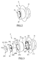
- FIG. 2 is an assembled perspective view of a first embodiment of a lamp according to the present invention
- FIG. 3 is an exploded perspective view of the first embodiment
- FIG. 4 is an exploded perspective view of a first decorating member and a securing unit of the first embodiment
- FIG. 5 is a fragmentary schematic sectional view of the first decorating member and the securing unit
- FIGS. 6 to 8 are partly exploded perspective views of the first embodiment with different decorating members
- FIG. 9 is an exploded perspective view of a second embodiment of a lamp according to the present invention.
- FIG. 10 is a schematic sectional view of the second embodiment
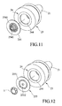
- FIG. 11 is a partly exploded perspective view of the second embodiment with a different decorating member
- FIG. 12 is a partly exploded perspective view of the second embodiment with another different decorating member
- FIG. 13 is an exploded perspective view of the third embodiment of a lamp according to the present invention.
- FIG. 14 is a schematic sectional view of the third embodiment.
- FIG. 15 is a fragmentary exploded perspective view of the third embodiment illustrating how a lens member is secured to a base.
- the first embodiment of a lamp 2 includes a base 21 , a light emitting module 22 mounted to the base 21 , a lens member 23 , a securing unit 24 , and a decorating unit 25 .
- the base 21 has a connecting surface 211 that faces the light emitting module 22 and that has an engaging portion 212 engaging the lens member 23 .
- the light emitting module 22 includes a printed circuit board (PCB) 221 connected to the connecting surface 211 , and a plurality of LEDs 222 mounted on the PCB 221 (see FIG. 10 ).
- PCB printed circuit board
- the lens member 23 has a light input surface 231 engaged with the engaging portion 212 of the connecting surface 211 of the base 21 , a light output surface 232 disposed in front of and spaced apart from the light input surface 231 along an axis, and a through hole 2300 extending through the light input surface 231 and the light output surface 232 .
- light emitted from the light emitting module 22 enters the lens member 23 through the light input surface 231 and exits the lens member 23 through the light output surface 232 .
- the light output surface 232 is larger than the light input surface 231 .
- the securing unit 24 has a securing portion 241 passing through the through hole 2300 of the lens member 23 and connected fixedly to the base 21 so that the lens member 23 is located between the securing unit 24 and the base 21 , a disk-shaped abutment portion 242 abutting against a front end of the lens member 23 and connected to the securing portion 241 , and a coupling portion 243 arranged on the abutment portion 242 .
- the coupling portion 243 extends forwardly from the center of the abutment portion 242 .
- the lens member 23 and the securing unit 24 are provided respectively with first and second engaging components 2301 , 2401 , and are connected to each other through engagement between the first and second engaging components 2301 , 2401 .
- the light output surface 232 of the lens member 23 has a stepped receiving portion 233 formed as a recess for receiving a peripheral part of the abutment portion 242 of the securing unit 24 .
- the decorating unit 25 is disposed within the light output surface 232 of the lens member 23 for decorating the lamp 2 or optically disposed for changing at least one of a wavelength, an output angle and a light field and so forth of the light passing through the lens member 23 .
- the decorating unit 25 has a first decorating member 251 , which has a first connecting section 2511 that is detachably connected to the coupling portion 243 of the securing unit 24 , and a first decorating section 2512 that is connected to the first connecting section 2511 at an end opposite to the coupling portion 243 of the securing unit 24 , and that does not cover the light output surface 232 of the lens member 23 such that the first decorating section 2512 is simply for decorating the lamp.
- the coupling portion 243 of the securing unit 24 in this embodiment has an annular wall surrounding the axis, defining a securing space therein, and formed with a plurality of angularly-spaced apart notches that extend parallel to the axis and an annular securing groove 2431 that surrounds the axis at the inner side of the coupling portion 243 .
- the first connecting section 2511 of the decorating unit 25 in this embodiment has a block inserted into the securing space and formed with an annular external protrusion 2510 that engages the annular securing groove 2431 .
- the annular wall of the coupling portion 243 due to the presence of the notches, is radially and outwardly deformed by the annular external protrusion 2510 when the annular external protrusion 2510 is moved along the axis until the annular external protrusion 2510 is slipped into the annular securing groove 2431 .
- the method of connecting the securing unit and the decorating unit is not limited to the disclosure herein.
- the decorating unit 25 has a second decorating member 252 , which can be interchanged with the first decorating member 251 according to the needs of different occasions.
- the second decorating member 252 has a second connecting section 2521 that is detachably connected to the coupling portion 243 of the securing unit 24 in the same manner as the coupling of the first connecting section 2511 of the first decorating member 251 to the coupling portion 243 of the securing unit 24 , and a second decorating section 2522 that is connected to the second connecting section 2521 at an end opposite to the coupling portion 243 of the securing unit 24 .
- the second decorating section 2522 is larger in area than the first decorating section 2512 of the first decorating member 251 , thereby covering the light output surface 232 of the lens member 23 ; namely, the decorating unit 25 is optically disposed to the lens member 23 so that the characteristics of the light emitted by the light output surface 232 is changeable by virtue thereof.
- the second decorating section 2522 may be configured as a color filter for changing the light color or have an outer surface formed with a plurality of microstructures (see FIG. 8 ) for changing the light field and so forth of the light passing through the lens member 23 .
- the microstructures may be configured as dots or rough structures, wherein they can be used to diffuse or focus the light emitted from the light output surface 232 ; or configured as prisms or elongated type structures such as V-cut structures or R-cut structures, wherein they can be used to bring on uniform distribution of the light field of the light emitted from the light output surface 232 .
- the second embodiment of the lamp 2 according to the present invention is similar to the first embodiment, except for the configurations of the securing unit 24 and the decorating unit 25 .
- the securing unit 24 includes a securing tube 244 passing through the through hole 2300 of the lens member 23 and connected fixedly to the base 21 , and an annular abutment portion 245 abutting against the front end of the lens member 23 , connected to the securing tube 244 at an end opposite to the base 21 and having the decorating unit 25 detachably connected thereto.
- the abutment portion 245 is received in the receiving portion 233 of the lens member 23 .
- the decorating unit 25 in this embodiment further can be replaced by a third decorating member 253 , which includes a third connecting section 2531 that is detachably connected to the annular abutment portion 245 , and a ring-shaped third decorating section 2532 that is connected to the third connecting section 2531 at an end opposite to the annular abutment portion 245 , and that covers the light output surface 232 of the lens member 23 .
- the third connecting section 2531 is tubular and slightly smaller in diameter than the securing tube 244 , so that it can insert into the securing tube 244 and be secured onto an inner surface of the securing tube 244 .
- the abovementioned configurations increase heat-dissipating efficiency of the lamp 2 by allowing air from the external environment to pass through the securing unit 24 and the decorating unit 25 .
- the third decorating section 2532 may also be configured as a color filter or have an outer surface formed with a plurality of microstructures for changing the wavelength or angle or light field of the light passing through the lens member 23 .
- the decorating unit 25 further can be replaced by a fourth decorating member 254 having a fourth decorating section 2541 that is detachably connected to a front end of the lens member 23 , and an auxiliary section 2542 that is connected to and surrounded by the fourth decorating section 2541 .
- the auxiliary section 2542 can be designed to have different decorating patterns and formed with a plurality of air holes to allow passage of air therethrough.
- the decorating unit 25 can further be replaced by a fifth decorating member 255 having a fifth decorating section 2551 that is detachably connected to a front end of the lens member 23 , and an auxiliary section 2552 that is connected to and surrounded by the fifth decorating section 2551 .
- the lamp 2 herein further comprises an ornament 3 connected detachably to the auxiliary section 2552 .
- the decoration style may be multiform by changing the design of the ornament 3 .
- the third embodiment of the lamp 2 according to the present invention is similar to the first and second embodiments, except for the structures and configurations of the base 21 , the securing unit 24 and the decorating unit 25 .
- the securing unit 24 is ring-shaped, is disposed in the base 21 and interposed between the PCB 221 and the lens member 23 , and has two L-shaped grooves 246 formed on a side facing the lens member 23 , and four angularly spaced-apart threaded through holes 247 . Two of the through holes 247 are formed in the grooves 246 .
- the base 21 of this embodiment includes four screw holes 214 .
- Four front screws 26 are provided to be inserted respectively and threadedly through the through holes 247 to engage respectively and threadedly the screw holes 214 so as to firmly fix the securing unit 24 to the base 21 .
- the lens member 23 further includes two protrusions 234 (only one is visible) that respectively engage the grooves 246 .
- the protrusions 234 of the lens member 23 are first inserted respectively into the grooves 246 of the securing unit 24 , and the lens member 23 is rotated relative to the securing unit 24 to be locked to the securing unit 24 .
- Each of the protrusions 234 is formed with a lock hole 235 .
- Two rear screws 27 are provided to extend through the base 21 and the securing unit 24 and engage respectively with the lock holes 235 so as to prevent rotation of the lens member 23 relative to the base unit 21 . Particularly, as illustrated by FIG.
- the lens member 23 is moved toward the securing unit 24 until the protrusions 234 respectively enter the grooves 246 , and is then rotated relative to the securing unit 24 to respectively enter spaces 248 (only one is shown) which are respectively next to the grooves 246 and which extend between the securing unit 24 and the base 21 to finish the assembly of the lens member 23 and the securing unit 24 .
- the decorating unit 25 has a sixth decorating member 256 having a sixth decorating section 2562 extending through the lens member 23 and the securing unit 24 , and a sixth connecting section 2561 connected detachably to the base 21 .
- the decorating unit 25 may be received in a threaded hole 213 defined by the connecting surface 211 of the base 21 by threaded engagement between the sixth connecting section 2561 and the threaded hole 213 (see FIG. 13 ), or the sixth connecting section 2561 may be configured to be connected detachably to the base 21 by being hooked on the connecting surface 211 of base 21 .
- the sixth decorating section 2562 does not cover the light output surface 232 .
- the first to sixth decorating members 251 , 252 , 253 , 254 , 255 , 256 can be interchanged according to practical requirements.
- the lamp 2 not only allows a user to detach and replace, for example, the first, fourth, fifth, and sixth decorating members 251 , 254 , 255 , 256 to suit their decorative needs, but also lets the user detach and replace, for example, the second and third decorating members 252 , 253 , which further provides a wide variety of customization options in terms of color, light field, etc. to achieve the user's desired lighting effects.
Landscapes
- Engineering & Computer Science (AREA)
- General Engineering & Computer Science (AREA)
- Physics & Mathematics (AREA)
- Microelectronics & Electronic Packaging (AREA)
- Optics & Photonics (AREA)
- Spectroscopy & Molecular Physics (AREA)
- Securing Globes, Refractors, Reflectors Or The Like (AREA)
- Planar Illumination Modules (AREA)
- Non-Portable Lighting Devices Or Systems Thereof (AREA)
Abstract
Description
Claims (26)
Applications Claiming Priority (3)
| Application Number | Priority Date | Filing Date | Title |
|---|---|---|---|
| TW103111975 | 2014-03-31 | ||
| TW103111975A | 2014-03-31 | ||
| TW103111975 | 2014-03-31 |
Publications (2)
| Publication Number | Publication Date |
|---|---|
| US20150276176A1 US20150276176A1 (en) | 2015-10-01 |
| US9719659B2 true US9719659B2 (en) | 2017-08-01 |
Family
ID=51187640
Family Applications (1)
| Application Number | Title | Priority Date | Filing Date |
|---|---|---|---|
| US14/668,168 Active 2035-08-18 US9719659B2 (en) | 2014-03-31 | 2015-03-25 | Lamp |
Country Status (4)
| Country | Link |
|---|---|
| US (1) | US9719659B2 (en) |
| EP (1) | EP2927561B1 (en) |
| CN (2) | CN103939857B (en) |
| TW (2) | TWI628393B (en) |
Cited By (1)
| Publication number | Priority date | Publication date | Assignee | Title |
|---|---|---|---|---|
| US20190301727A1 (en) * | 2018-03-28 | 2019-10-03 | Abl Ip Holding Llc | Loudspeaker luminaire with light pipe |
Families Citing this family (8)
| Publication number | Priority date | Publication date | Assignee | Title |
|---|---|---|---|---|
| US20180003374A1 (en) * | 2015-01-06 | 2018-01-04 | Erin Bulcao | Motion Activated Illumination Device for Use with a Toilet |
| USD859719S1 (en) | 2015-06-23 | 2019-09-10 | Axis Lighting Inc. | Luminaire |
| US10288238B2 (en) | 2015-06-23 | 2019-05-14 | Axis Lighting Inc. | Supporting accessories for ceiling structures |
| EP3263981B1 (en) * | 2016-06-28 | 2019-03-06 | OSRAM GmbH | A method of producing optical elements for lighting devices and corresponding optical element |
| CN109519891B (en) * | 2018-12-25 | 2024-06-07 | 赛尔富电子有限公司 | Lamp set |
| CN210979554U (en) * | 2019-10-16 | 2020-07-10 | 漳州立达信光电子科技有限公司 | Ceiling lamp |
| WO2021154525A1 (en) * | 2020-01-31 | 2021-08-05 | American Sterilizer Company | Light head with rotating lens assembly and method of operating same |
| CN114679911B (en) * | 2020-10-09 | 2024-08-27 | 瑞仪光电(苏州)有限公司 | Lighting |
Citations (30)
| Publication number | Priority date | Publication date | Assignee | Title |
|---|---|---|---|---|
| WO1998055798A2 (en) | 1997-06-04 | 1998-12-10 | Simon Jerome H | Reflective and refractive wave lens for light shaping |
| US20060007692A1 (en) * | 2004-07-07 | 2006-01-12 | Hsien Chen S | Lamp assembly |
| US7222988B2 (en) * | 2004-09-21 | 2007-05-29 | Gober David A | Display device for illuminating optical storage disks for visual display and method of using the same |
| CN201289044Y (en) | 2008-10-28 | 2009-08-12 | 深圳市浪尖工业产品造型设计有限公司 | LED illuminating device |
| US20100073960A1 (en) * | 2008-09-22 | 2010-03-25 | Yi-Hsueh Yang | Color pattern forming device |
| US20100085737A1 (en) * | 2008-10-03 | 2010-04-08 | Chin-Sheng Yang | Candle like lighting device |
| JP2010250966A (en) | 2009-04-10 | 2010-11-04 | Toshiba Lighting & Technology Corp | lighting equipment |
| CN201696900U (en) | 2010-01-08 | 2011-01-05 | 大连九久光电制造有限公司 | LED tube light |
| CN102052623A (en) | 2011-01-30 | 2011-05-11 | 陈晓锋 | A New Type of Decorative Lighting Lamp |
| TWM404310U (en) | 2010-12-03 | 2011-05-21 | Wing Lian Lighting Co Ltd | Art lamps having light transmissive decoration plate structure |
| US7988322B2 (en) | 2009-03-21 | 2011-08-02 | Fu Zhun Precision Industry (Shen Zhen) Co., Ltd. | Decorative lamp |
| US20110291560A1 (en) | 2010-06-01 | 2011-12-01 | Young Lighting Technology Corporation | Illuminating device |
| US20110309735A1 (en) * | 2010-06-18 | 2011-12-22 | Parker Jeffery R | Light bulb using solid-state light sources |
| CN202613256U (en) | 2012-05-11 | 2012-12-19 | 云南鼎坤科技有限公司 | Low power surface-mounted type LED (Light Emitting Diode) down lamp with ultrathin structure |
| WO2013013514A1 (en) | 2011-07-28 | 2013-01-31 | 厦门立明光电有限公司 | Illuminating led lamp |
| US20130038195A1 (en) * | 2011-08-09 | 2013-02-14 | Rambus Inc. | Light bulb with thermal features |
| CN203036387U (en) | 2012-11-30 | 2013-07-03 | 深圳市奥拓光电科技有限公司 | Light-emitting diode (LED) side lighting panel lamp |
| US8487518B2 (en) * | 2010-12-06 | 2013-07-16 | 3M Innovative Properties Company | Solid state light with optical guide and integrated thermal guide |
| CN203190245U (en) | 2012-11-14 | 2013-09-11 | 许少群 | Luminaire structure combined with multiple illuminants |
| CN203202768U (en) | 2013-04-23 | 2013-09-18 | 苗光夫 | Novel LED ceiling lamp |
| CN103322442A (en) | 2012-03-23 | 2013-09-25 | 英志企业股份有限公司 | Lamp structure |
| CN103335277A (en) | 2013-06-05 | 2013-10-02 | 江苏华安高技术安防产业有限公司 | Light guide lamp with cavity structure and manufacturing method of light guide lamp |
| US20130265754A1 (en) | 2009-05-12 | 2013-10-10 | Global Lighting Technologies Inc. | Illumination apparatus |
| WO2013190979A1 (en) | 2012-06-19 | 2013-12-27 | 株式会社 東芝 | Lighting device |
| EP2679896A1 (en) | 2012-06-29 | 2014-01-01 | Kabushiki Kaisha Toshiba | Lighting device |
| CN103574516A (en) | 2013-07-22 | 2014-02-12 | 瑞仪光电股份有限公司 | Light guide element capable of controlling light beam angle and lamp |
| US20140092580A1 (en) * | 2012-10-01 | 2014-04-03 | Rambus Delaware Llc | Led lamp and led lighting assembly |
| TWM481330U (en) | 2013-11-20 | 2014-07-01 | Jin-Sheng Yang | Optical lamp decoration |
| WO2014138163A1 (en) | 2013-03-05 | 2014-09-12 | Terralux, Inc. | Light-emitting diode light bulb generating direct and decorative illumination |
| US8957597B2 (en) * | 2010-09-30 | 2015-02-17 | Lite-On Electronics (Guangzhou) Limited | Luminaire |
Family Cites Families (2)
| Publication number | Priority date | Publication date | Assignee | Title |
|---|---|---|---|---|
| TW454851U (en) * | 2000-09-18 | 2001-09-11 | Shen Wei Hung | Decorating connector structure |
| CN203322987U (en) * | 2013-05-23 | 2013-12-04 | 陈小清 | Split-type LED (light emitting diode) light source decorative lamp structure |
-
2014
- 2014-05-06 CN CN201410189405.4A patent/CN103939857B/en active Active
- 2014-05-06 CN CN201710144000.2A patent/CN107091462A/en not_active Withdrawn
-
2015
- 2015-01-09 TW TW106100639A patent/TWI628393B/en active
- 2015-03-25 US US14/668,168 patent/US9719659B2/en active Active
- 2015-03-27 TW TW104110024A patent/TW201537086A/en unknown
- 2015-03-30 EP EP15161610.9A patent/EP2927561B1/en active Active
Patent Citations (32)
| Publication number | Priority date | Publication date | Assignee | Title |
|---|---|---|---|---|
| WO1998055798A2 (en) | 1997-06-04 | 1998-12-10 | Simon Jerome H | Reflective and refractive wave lens for light shaping |
| US20060007692A1 (en) * | 2004-07-07 | 2006-01-12 | Hsien Chen S | Lamp assembly |
| US7222988B2 (en) * | 2004-09-21 | 2007-05-29 | Gober David A | Display device for illuminating optical storage disks for visual display and method of using the same |
| US20100073960A1 (en) * | 2008-09-22 | 2010-03-25 | Yi-Hsueh Yang | Color pattern forming device |
| US20100085737A1 (en) * | 2008-10-03 | 2010-04-08 | Chin-Sheng Yang | Candle like lighting device |
| CN201289044Y (en) | 2008-10-28 | 2009-08-12 | 深圳市浪尖工业产品造型设计有限公司 | LED illuminating device |
| US7988322B2 (en) | 2009-03-21 | 2011-08-02 | Fu Zhun Precision Industry (Shen Zhen) Co., Ltd. | Decorative lamp |
| JP2010250966A (en) | 2009-04-10 | 2010-11-04 | Toshiba Lighting & Technology Corp | lighting equipment |
| US20130265754A1 (en) | 2009-05-12 | 2013-10-10 | Global Lighting Technologies Inc. | Illumination apparatus |
| CN201696900U (en) | 2010-01-08 | 2011-01-05 | 大连九久光电制造有限公司 | LED tube light |
| US20110291560A1 (en) | 2010-06-01 | 2011-12-01 | Young Lighting Technology Corporation | Illuminating device |
| US20110309735A1 (en) * | 2010-06-18 | 2011-12-22 | Parker Jeffery R | Light bulb using solid-state light sources |
| US8957597B2 (en) * | 2010-09-30 | 2015-02-17 | Lite-On Electronics (Guangzhou) Limited | Luminaire |
| TWM404310U (en) | 2010-12-03 | 2011-05-21 | Wing Lian Lighting Co Ltd | Art lamps having light transmissive decoration plate structure |
| US8487518B2 (en) * | 2010-12-06 | 2013-07-16 | 3M Innovative Properties Company | Solid state light with optical guide and integrated thermal guide |
| CN102052623A (en) | 2011-01-30 | 2011-05-11 | 陈晓锋 | A New Type of Decorative Lighting Lamp |
| WO2013013514A1 (en) | 2011-07-28 | 2013-01-31 | 厦门立明光电有限公司 | Illuminating led lamp |
| US20140167593A1 (en) | 2011-07-28 | 2014-06-19 | Leeleds Lighting (Xiamen) Co., Ltd. | Led illumination lamp |
| WO2013023022A2 (en) | 2011-08-09 | 2013-02-14 | Rambus Inc. | Light bulb with thermal features |
| US20130038195A1 (en) * | 2011-08-09 | 2013-02-14 | Rambus Inc. | Light bulb with thermal features |
| CN103322442A (en) | 2012-03-23 | 2013-09-25 | 英志企业股份有限公司 | Lamp structure |
| CN202613256U (en) | 2012-05-11 | 2012-12-19 | 云南鼎坤科技有限公司 | Low power surface-mounted type LED (Light Emitting Diode) down lamp with ultrathin structure |
| WO2013190979A1 (en) | 2012-06-19 | 2013-12-27 | 株式会社 東芝 | Lighting device |
| EP2679896A1 (en) | 2012-06-29 | 2014-01-01 | Kabushiki Kaisha Toshiba | Lighting device |
| US20140092580A1 (en) * | 2012-10-01 | 2014-04-03 | Rambus Delaware Llc | Led lamp and led lighting assembly |
| CN203190245U (en) | 2012-11-14 | 2013-09-11 | 许少群 | Luminaire structure combined with multiple illuminants |
| CN203036387U (en) | 2012-11-30 | 2013-07-03 | 深圳市奥拓光电科技有限公司 | Light-emitting diode (LED) side lighting panel lamp |
| WO2014138163A1 (en) | 2013-03-05 | 2014-09-12 | Terralux, Inc. | Light-emitting diode light bulb generating direct and decorative illumination |
| CN203202768U (en) | 2013-04-23 | 2013-09-18 | 苗光夫 | Novel LED ceiling lamp |
| CN103335277A (en) | 2013-06-05 | 2013-10-02 | 江苏华安高技术安防产业有限公司 | Light guide lamp with cavity structure and manufacturing method of light guide lamp |
| CN103574516A (en) | 2013-07-22 | 2014-02-12 | 瑞仪光电股份有限公司 | Light guide element capable of controlling light beam angle and lamp |
| TWM481330U (en) | 2013-11-20 | 2014-07-01 | Jin-Sheng Yang | Optical lamp decoration |
Non-Patent Citations (7)
| Title |
|---|
| Chinese Search Report dated Dec. 14, 2015, issued in Application No. 2014101894054 filed Mar. 31, 2014 with English translation. |
| Chinese Search Report dated Jun. 23, 2016, issued in Application No. 2015100978752 with partial English translation. |
| Chinese Search Resort issued in App. No. 2014101894054 dated Aug. 10, 2016 (w/ translation). |
| Extended European Search Report issued in EP Application No. 15161610.9 dated Jul. 16, 2015. |
| Notice of Allowance issued in U.S. Appl. No. 14/667,700 dated May 5, 2017. |
| Taiwan Search Report dated Jun. 14, 2016, issued in Application No. 104100779 with partial English translation. |
| Taiwan Search Report dated Mar. 28, 2016, issued in Application No. 104110024 with partial English translation. |
Cited By (1)
| Publication number | Priority date | Publication date | Assignee | Title |
|---|---|---|---|---|
| US20190301727A1 (en) * | 2018-03-28 | 2019-10-03 | Abl Ip Holding Llc | Loudspeaker luminaire with light pipe |
Also Published As
| Publication number | Publication date |
|---|---|
| US20150276176A1 (en) | 2015-10-01 |
| CN107091462A (en) | 2017-08-25 |
| TWI563204B (en) | 2016-12-21 |
| TW201537086A (en) | 2015-10-01 |
| TW201716723A (en) | 2017-05-16 |
| TWI628393B (en) | 2018-07-01 |
| EP2927561A1 (en) | 2015-10-07 |
| EP2927561B1 (en) | 2017-02-22 |
| CN103939857A (en) | 2014-07-23 |
| CN103939857B (en) | 2017-04-12 |
Similar Documents
| Publication | Publication Date | Title |
|---|---|---|
| US9719659B2 (en) | Lamp | |
| US9683716B2 (en) | Lens having densely-distributed convex facets on its entrance and exit surfaces | |
| US10386023B2 (en) | LED light fixture and assembly method therefor | |
| CN105202394B (en) | Lens combination and lighting device using lens combination | |
| CN106716002B (en) | Decorative LED integrated luminaire | |
| US20160312977A1 (en) | Total internal reflection lens with step-shaped front surface and central convex region | |
| CN103574501B (en) | Lens, lens array and lighting device | |
| EP3832197B1 (en) | Lampshade structure and lamp | |
| US20090207610A1 (en) | Combination rear lighting system | |
| US9033563B1 (en) | Vehicle headlight assembly | |
| US20130322091A1 (en) | Lamp accent assembly and method | |
| US20210109332A1 (en) | Optical system for an led wash luminaire | |
| EP3631287B1 (en) | Luminaire | |
| US20160033111A1 (en) | Electric light fixture | |
| CN104482437B (en) | A kind of illuminator | |
| US20070183165A1 (en) | Direct Lighting Vehicular Lamp | |
| CN205331830U (en) | LED lamps | |
| US10288258B1 (en) | Lighting module | |
| GB2504686A (en) | A downlighter or uplighter light source | |
| CN104235631B (en) | LED lamp | |
| CN201297540Y (en) | Projection lamp with light transmission | |
| TWM549173U (en) | Headlight with spatial depth of field | |
| TWM519219U (en) | Beam control element | |
| CN102759034A (en) | Light-emitting diode lamp tube | |
| CN104696737A (en) | Lamp and optical module thereof |
Legal Events
| Date | Code | Title | Description |
|---|---|---|---|
| AS | Assignment |
Owner name: RADIANT OPTO-ELECTRONICS CORPORATION, TAIWAN Free format text: ASSIGNMENT OF ASSIGNORS INTEREST;ASSIGNORS:JU, CHIH-HUNG;HUANG, GUO-HAO;CHEN, KUN-FENG;AND OTHERS;REEL/FRAME:035252/0585 Effective date: 20150312 |
|
| STCF | Information on status: patent grant |
Free format text: PATENTED CASE |
|
| MAFP | Maintenance fee payment |
Free format text: PAYMENT OF MAINTENANCE FEE, 4TH YEAR, LARGE ENTITY (ORIGINAL EVENT CODE: M1551); ENTITY STATUS OF PATENT OWNER: LARGE ENTITY Year of fee payment: 4 |
|
| MAFP | Maintenance fee payment |
Free format text: PAYMENT OF MAINTENANCE FEE, 8TH YEAR, LARGE ENTITY (ORIGINAL EVENT CODE: M1552); ENTITY STATUS OF PATENT OWNER: LARGE ENTITY Year of fee payment: 8 |