US9716614B2 - Infrastructure correlation protocol - Google Patents
Infrastructure correlation protocol Download PDFInfo
- Publication number
- US9716614B2 US9716614B2 US15/162,419 US201615162419A US9716614B2 US 9716614 B2 US9716614 B2 US 9716614B2 US 201615162419 A US201615162419 A US 201615162419A US 9716614 B2 US9716614 B2 US 9716614B2
- Authority
- US
- United States
- Prior art keywords
- data
- nodes
- communication infrastructure
- infrastructure
- correlation
- Prior art date
- Legal status (The legal status is an assumption and is not a legal conclusion. Google has not performed a legal analysis and makes no representation as to the accuracy of the status listed.)
- Active, expires
Links
Images


Classifications
-
- H—ELECTRICITY
- H04—ELECTRIC COMMUNICATION TECHNIQUE
- H04L—TRANSMISSION OF DIGITAL INFORMATION, e.g. TELEGRAPHIC COMMUNICATION
- H04L41/00—Arrangements for maintenance, administration or management of data switching networks, e.g. of packet switching networks
- H04L41/06—Management of faults, events, alarms or notifications
- H04L41/0631—Management of faults, events, alarms or notifications using root cause analysis; using analysis of correlation between notifications, alarms or events based on decision criteria, e.g. hierarchy, tree or time analysis
-
- H—ELECTRICITY
- H04—ELECTRIC COMMUNICATION TECHNIQUE
- H04L—TRANSMISSION OF DIGITAL INFORMATION, e.g. TELEGRAPHIC COMMUNICATION
- H04L43/00—Arrangements for monitoring or testing data switching networks
- H04L43/08—Monitoring or testing based on specific metrics, e.g. QoS, energy consumption or environmental parameters
- H04L43/0805—Monitoring or testing based on specific metrics, e.g. QoS, energy consumption or environmental parameters by checking availability
- H04L43/0817—Monitoring or testing based on specific metrics, e.g. QoS, energy consumption or environmental parameters by checking availability by checking functioning
-
- H04W4/005—
-
- H—ELECTRICITY
- H04—ELECTRIC COMMUNICATION TECHNIQUE
- H04W—WIRELESS COMMUNICATION NETWORKS
- H04W4/00—Services specially adapted for wireless communication networks; Facilities therefor
- H04W4/02—Services making use of location information
- H04W4/029—Location-based management or tracking services
-
- H—ELECTRICITY
- H04—ELECTRIC COMMUNICATION TECHNIQUE
- H04W—WIRELESS COMMUNICATION NETWORKS
- H04W4/00—Services specially adapted for wireless communication networks; Facilities therefor
- H04W4/70—Services for machine-to-machine communication [M2M] or machine type communication [MTC]
-
- H—ELECTRICITY
- H04—ELECTRIC COMMUNICATION TECHNIQUE
- H04W—WIRELESS COMMUNICATION NETWORKS
- H04W4/00—Services specially adapted for wireless communication networks; Facilities therefor
- H04W4/02—Services making use of location information
Abstract
The performance and/or state of communication infrastructure that transmits data may be correlated with the transmitted data. In one implementation, a method may include receiving infrastructure data relating to a state of communication infrastructure; receiving identifiers corresponding to machine to machine nodes that transmit data using the communication infrastructure; storing the infrastructure data to associate the infrastructure data to the identifiers corresponding to the nodes; generating structured data that represents a correlation of the received data and the infrastructure data; and providing at least a portion of the structured data, to one or more devices relating to the plurality of computing nodes or the communication infrastructure.
Description
This application is a continuation of co-pending U.S. patent application Ser. No. 14/012,926, titled “INFRASTRUCTURE CORRELATION PROTOCOL,” filed Aug. 28, 2013, the contents of which are incorporated herein by reference in their entirety.
Machine to Machine (M2M) communications refer to technologies that allow devices, which may be referred to as nodes of an M2M network, to communicate with one another over wired or wireless networks. An M2M node may include a sensor, meter, or other device that captures an “event” (temperature, inventory level, etc.), which is relayed through a network (wireless, wired, or hybrid) to an application that translates the captured event into meaningful information (e.g., items need to be restocked).
Data from nodes in an M2M network (referred to as “M2M data” herein) may be received and analyzed at a central site (referred to as an “application server” herein). The “application server,” as used herein, may refer to one or more server devices and or software components, which may be physically distributed or located at a single location. Typically, the application server, or users associated with the application server, may make decisions, such as business or process decisions, based on an analysis of the M2M data associated with some or all of the nodes in the M2M network. It can be important for the decision making process of the M2M network/application server that the data received by the application server is not corrupted, or otherwise adversely affected, during the transport of the data from the M2M nodes to the application server.
The following detailed description refers to the accompanying drawings. The same reference numbers in different drawings may identify the same or similar elements.
Techniques described herein may provide for an analysis of the performance of infrastructure, such as network infrastructure, that may transmit data. The transmitted data may correspond to M2M data, or more generally, to data transmitted by any computing device across network infrastructure. The analysis may include correlating the operation of the infrastructure with the data. Based on the analysis, actions may be taken and/or reports may be generated. The analysis may be provided as a service by an operator of the infrastructure.
Assume that an operator of the application component notices, or receives an alert regarding, a questionable data point in the M2M data received by the application component. As shown in FIG. 1 , for example, a plot of M2M Application data versus time (e.g., a plot of sensed temperatures, sensed soil moisture levels, etc., versus time) may include a section in which the M2M data exhibits an abrupt drop off, which may indicate data loss. The operator of the application server may wish to investigate the source of the potential data loss. The operator may query the correlation component to view infrastructure data corresponding to the M2M data that exhibits the potential data loss. The operator may determine, for example, that a particular network element (NE) responsible for delivering the M2M data, corresponding to the data loss, may have been experienced an error over the time period corresponding to the data loss, or an individual reporting device may have gone offline for some reason.
In this manner, operators of the application server may be able to obtain infrastructure data relating to the M2M data received by the application server. Being able to obtain infrastructure data relating to M2M data may be useful in a number of scenarios, such as when diagnosing the cause of M2M data loss or corruption, or in viewing the robustness of the communication infrastructure over a particular time period. In general, if the M2M data is somehow corrupt, or data is missing and associated reasons for the data being missing are not understood, the application server may process the data verbatim, and undesirable results could occur. More specifically, data received by the application server should not be corrupted, should be received with awareness of the completeness of the data, and should not be otherwise adversely affected during the transport of the data from the M2M nodes to the application server. The definition of what adequately constitutes a complete data set may be desirable for the ability of the M2M system to function properly.
In some implementations, in addition to providing reports to the application server, the correlation component may perform actions based on the analysis of the infrastructure data and/or M2M data. For example, the correlation component may determine that particular data items, of the M2M data, may have been lost in transmission and may request that the corresponding M2M nodes retransmit the data. As another example, the correlation component may determine that a particular network section or network element is down, and may correspondingly instruct one or more M2M nodes to delay sending M2M data.
In one implementation, the correlation protocol, as described herein, may be used in the context of communications with respect to M2M systems. The example of environment 200 will be particularly described in the context of M2M systems.
As illustrated, environment 200 may correspond to an environment in which one or more M2M networks are implemented. An M2M network may be defined as a number of M2M nodes that transmit data to one or more application servers.
A number of M2M networks 210-1 through 210-N (N>=1), which may be referred to collectively as M2M networks 210 or singularly as an M2M network 210, are illustrated in FIG. 2 . Each M2M network 210 may include one or more nodes 215 (illustrated as a circle in FIG. 2 ). The nodes of a M2M network 210 may communicate, via communication infrastructure 220, with one or more application servers 230-1 through 230-J (J>=1), which may be referred to collectively as application servers 230 or singularly as an application server 230. Correlation component 240 may receive M2M data from nodes 215 and infrastructure data from communication infrastructure 220. Additionally, external data sources 250 may supply data to one or more of M2M networks 210, communication infrastructure 220, application servers 230, and/or correlation component 240.
Each node 215 may include a device that may implement one or more sensing components and a communication component. The sensing component may include, for example, a temperature sensor, a humidity sensor, a light sensor, a camera, a video camera, a geo-positioning element (e.g., a GPS component), and/or other sensors that generate or monitor data that relates to the environment of a particular node 215. The communication component may include a wireless or wired communication circuit that allows node 215 to transmit sensed data to another node and/or to communication infrastructure 220. For example, the communication component may include a cellular radio, a short range radio, circuitry to communicate over a wired link, or another communication technology.
As one example of an implementation of environment 200, M2M network 210-1 may correspond to an agriculture-based M2M network that monitors environmental conditions for a fruit farm and, M2M network 210-2 may correspond to M2M network that monitors inventory for a retailer, and M2M network 212-N may correspond to a healthcare-based M2M network that monitors the status of equipment in a hospital.
Although FIG. 2 illustrates example components of an environment 200, in other implementations, environment 200 may contain fewer components, different components, differently arranged components, or additional components than those depicted in FIG. 2 . Alternatively, or additionally, one or more components of environment 200 may perform one or more other tasks described as being performed by one or more other components of environment 200.
As shown in FIG. 3 , nodes 215 may connect to base stations 320 and/or to a packet data network (PDN) 350. In an LTE environment, base stations 320 may take the form of evolved node Bs (eNodeBs). The environment of FIG. 3 may further include serving gateway (SGW) 325, mobility management entity (MME) 330, packet data network gateway (PGW) 345, policy charging and rules function (PCRF) 340. Application server 230 and correlation component 240 may connect through PDN 350 and/or the EPS/LTE network.
MME 330 may include one or more computation and communication devices that perform signaling in environment 200. MME 330 may, for example, be responsible for authenticating nodes 215, maintaining location information for nodes 215, and selecting a PGW 345 to service a particular node 215. MME 330 may also operate to establish bearer channels associated with a session with node 215, to hand off node 215 from the EPS to another network, to hand off node 215 from the other network to the EPS, and/or to perform other operations. MME 330 may perform policing operations on traffic destined for and/or received from node 215.
The quantity of devices and/or networks, illustrated in FIG. 3 , is provided for explanatory purposes only. In practice, there may be additional devices and/or networks; fewer devices and/or networks; different devices and/or networks; or differently arranged devices and/or networks than illustrated in FIG. 3 . Alternatively, or additionally, one or more of the devices, shown in FIG. 3 , may perform one or more functions described as being performed by another one or more of the devices of FIG. 3 .
In one implementation, data structure 400 may be implemented, by correlation component 240, as a relational database. In general, a relational database may include a database that has a collection of tables of data items which may be formally described and organized according to the relational model. In a relational database, each table schema may identify a primary column used for identifying a row called the primary key. Tables may be related to one another by using a foreign key, in one table, that points to the primary key, in another table.
As illustrated in FIG. 4 , data structure 400 may conceptually include three sections, which, in the context of a relational database, may be implemented, for example, as three tables. The three tables may include: M2M node identifier table 410, M2M data table 420, and infrastructure data table 430.
M2M node identifier table 410 may store information used to identify nodes 215 of M2M systems 210. In some implementations, instead of identifying M2M data at the node level, M2M node identifier table 410 may store information identifying M2M systems 210. Nodes 215 may be identified by, for example, the IP address of the node, a mobile device serial number (for nodes that connect through a wireless network), a telephone number associated with the node (for nodes that connect through a wireless network), or another identifier assigned by the operator of communication infrastructure 220 and/or the operator of a particular M2M system 210.
In one implementation, when a node 215 or M2M system 210 initially begins to use, or registers with, correlation component 240, correlation component 240 may write an entry that identifies the node 215 or the M2M system 210, to M2M node identifier table 410. For example, when a node 215, associated with a mobile telephone number, first transmits M2M data to M2M infrastructure component 240, node 215 may register with correlation component 240 and, in response, correlation component 240 may write the mobile telephone number to M2M nodes identifier table 410.
M2M data table 420 may store the M2M data generated by nodes 215. As previously mentioned, M2M data may generally include data sensed, or otherwise generated, by nodes 215. The values in M2M data table 420 may thus include, for example, values representing temperature, humidity, light intensity, images, video, geo-positioning data, or other information. Each entry in M2M data table 420 may be associated with a foreign key that points back to M2M node identifier table 410 (e.g., a foreign key may be the identifier for a particular node 215, as stored in M2M node identifier table 410). In this manner, this foreign key may indicate from which node 215 the data, stored in a particular entry of table 420, was received. In some implementations, entries in M2M data table 420 may be associated with additional information, such as a timestamp value indicating when the M2M data was received by correlation component 240.
Infrastructure data table 430 may include data relating to the state of communication infrastructure 220. The data stored in infrastructure data table 430 may be stored in a way that associates particular items of infrastructure data to those of nodes 215 to which the particular items of infrastructure data are relevant. For example, the infrastructure data may include values describing the congestion level, over time, at a particular base station 320. This infrastructure dated may be particularly relevant to nodes 215 that connect through a particular base station 320. Infrastructure data table 430 may also include correspondences between particular infrastructure elements (e.g., routers, base stations, network links) and the nodes 215 to which the infrastructure elements are relevant. For example, when a node newly attaches to a particular base station 320, infrastructure data table 430 may be updated to include information indicate the attachment of the node to the base station. As is also illustrated in FIG. 4 , some entries in infrastructure data table 430 may correspond to multiple nodes (e.g., a link congestion level value may be relevant to multiple nodes) and a single node may be associated with multiple entries in infrastructure data table 430.
In general, the infrastructure data, stored by infrastructure data table 430, may relate to any information, obtainable from communication infrastructure 220, that may be relevant to the connectivity of nodes 215 to application servers 230. Non-limiting examples of the type of information that may be defined by the infrastructure data include: (1) the operational state of network elements (e.g., whether a particular routers, switches, base stations are online or offline, etc.); (2) congestion levels at various links in communication structure 220; (3) congestion levels for radio links (e.g., radio links between nodes 215 and base stations 320); (4) signal strength at nodes 215; (5) and/or an indication of the amount of operational redundancy of the various network elements communication infrastructure 220 (e.g., the number of backup links or the number of backup routers corresponding to a particular portion of communication infrastructure 220). In one implementation, infrastructure data may be obtained from network elements in communication structure 220. Alternatively or additionally, the M2M data transmitted by nodes 215 may be augmented to include data that is measured by nodes 215, such as an indication of the radio signal strength received by a node 215, battery level of the node 215, or other information that may be determined by node 215 and that may be that may be relevant to the connectivity of node 215 to an application server 230.
In some implementations, the M2M data and the infrastructure data may be received, from M2M nodes 215 and from communication infrastructure 220, using one or more protocols, called correlation protocols herein, that may define formatting, reporting, and/or other features relating to the structure of the received information. The correlation protocol may exist and function alongside existing status communication protocols, such as SNMP (Simple Network Management Protocol), or the correlation protocol may serve as the primary means for communicating and controlling status messages. By requiring data from M2M nodes 215 and from communication infrastructure 220 to conform to the correlation protocol, correlation component 240 may be able to efficiently and effectively process and use the information received from M2M nodes 215, communication infrastructure 220, and/or external sources 250. As an example of the operation of the correlation protocol, the correlation protocol may specify specific data formats, specific values that should be included with the received correlation information (e.g., a timestamp value), and/or specific categories or tags that should be associated with information received from M2M nodes 215 and/or communication infrastructure 220. For instance, items of data received from M2M nodes 215 may be explicitly identified, by the transmitting M2M node 215, with a specific data type, such as a type field indicating that a particular data item is a temperature value, humidity value, soil moisture value, altitude value, velocity value, etc. Similarly, items of data received from communication infrastructure 220 may be explicitly identified with a specific infrastructure data type, such as a type field indicating that the data item defines a particular router performance metric, defines a particular radio interface performance metric, defines a particular network quality of service metric, etc. As another example, data items received from M2M nodes 215 and communication infrastructure 220 may each be associated with a field identifying the role of the network element that generated the data item (e.g., a router, firewall, M2M node, etc.).
A number of different techniques may be used to operatively connect correlation component 240 to the M2M data, application server 230, and external source 250. FIGS. 5A and 5B illustrate example network architectures used to operatively connect correlation e component 240 to the M2M data, application server 230, and/or external source 250.
As illustrated in FIG. 5A , M2M data, from nodes 215, may be transmitted to correlation component 240, which may then make the M2M data available to application server 230. For example, the operator of correlation component 240 may make available an application programming interface (API) to the operators of M2M systems 210. The API may include specific formats and/or protocols that indicate how nodes 215 are to initially register with correlation component 240 and acceptable formats for M2M data received at correlation component 240. As is further illustrated in FIG. 5 , application server 230 may query correlation component 240 to obtain the M2M data as well as to obtain information relating to the correlation between the M2M data and the infrastructure data (M2M data/infrastructure data correlation information). For example, with respect to the M2M data, application server 230 may subscribe or register to receive a particular subset of the M2M data in which application server 230 is interested. Similarly, application server 230 (or an operator of application server 230) may determine to examine the information relating to the correlation between the M2M data on the infrastructure data, application server 230 may similarly query correlation component 240 to obtain this information.
The received M2M data (block 610) and the received infrastructure data (block 620) may be stored in a relational database that includes a data structure similar to that discussed above with respect to FIG. 4 . The receiving of the M2M data and the infrastructure data may also include validating the received data, such as by checking the data for errors and compliance with the correlation protocol.
In some implementations, data, such as correlation data, may be feed back into system 200 to create a feedback loop. For example, substantive M2M data, generated by an M2M node, may be analyzed by an external device or service, potentially modified, and then reintroduced into system 200. Such a scenario may create a loop in which the data is retransmitted to the external device or service. In some implementations, the error checking performed in block 610 may include checking for and correcting unstable feedback loops. A feedback loop factor value may be assigned to correlation data and is to be defined in the correlation protocol. A feedback decay factor can define attributes of feedback that are acceptable, such as the passage of time, passage of distance, iterations of correlation data that contain some parts of repeated information. For example, Node 1 transmits temperature T at time 0h00m00s, 0h00m30s, 0h01m00s, . . . (every 30 seconds). Node 1 also transmits its location, but only once every 1 minute. So, the location data for temperature sample T would be the same at times 0h00m00s, 0h00m30s, as temperature samples T are taken. The function of feedback control within the correlation protocol would be to set acceptable thresholds for certain data sets. In this example, such measurements are acceptable. However, if data is coming from the sensor itself, and also coming from external subscription sources (e.g., external data from external source 250), and the same node N, with same temperature T measurements are received, the feedback loop correction function can manage such duplicates and parse/remove data in the correlation, as indicated by the correlation protocol. This may help to ensure that correlation data is not received and processed in such a way as to damage the value of data, and/or performance of the system.
In some implementations, when determining the correlation between the received M2M data and infrastructure data, models and/or other functions (e.g., externally supplied functions) may be used to intelligently determine which data items, associated with the infrastructure data, affect the M2M data.
In some implementations, the request received in block 640 may be a request that is stored by correlation component 240 and that may be used to generate automatic actions by correlation component 240. For example, correlation component 240 may store rules, that when triggered, cause actions to be taken with respect to nodes 215, communication infrastructure 220, and/or application servers 230. For example, a trigger may be activated when a certain network link is detected to be down, and may cause one or more affected nodes 215 to be notified and/or a user of an application server 230 to be notified. As another example, the trigger may cause a message to be sent to an external application that may in some way operate to control an M2M system 210.
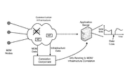
As illustrated in FIG. 7 , concepts described herein may be conceptually divided into the categories: infrastructure, correlation, M2M applications (M2M apps), and external sources. The infrastructure category may refer to the various types of data items that may be received from communication infrastructure 220. The M2M applications category may refer to the various types of data items that may be received from nodes 215. Correlation category may refer to the operations, by correlation component 240, in generating and using the structured correlation data. The external sources category may refer to data generated by other entities, such as external/third party/commercial/private data providers, and may be useful to the operation of correlation component 240 in generating or using the structured correlation data. Note also that some correlation data may not be used in all cases, in which case the correlation protocol will manage policies regarding use. In some cases, for example, location data may need to be truncated to protect privacy. In that case, data sent to external sources, or otherwise acted upon, may require modification by correlation component 240.
Data in the infrastructure category may generally relate to communication infrastructure 220. As illustrated, infrastructure data may include data relating to categories such as fixed (e.g., wired) core network, security, a wireless core network, a wireless radio frequency (RF) network, and hosting/cloud components of communication infrastructure 220. As is further illustrated in FIG. 7 , each category may include multiple sub-categories of data. The fixed core network category may include the sub-categories routers, switches, circuits, quality of service (QoS), caching, and multicasting. The security category may include the sub-categories firewall, access control, policies, and physical access. The wireless core network category may include the sub-categories cell base station, BSC, PDSN/FA/HA/EHA, infrastructure, network, and AAA. The wireless RF network category may include the sub-categories cellular radio, service, handoff control, session control, and QoS. The hosting/cloud category may include the sub-categories servers, OS, and virtualization.
Data in the M2M applications category may generally relate to the M2M data generated by nodes 215. As illustrated in FIG. 7 , the M2M data may include data relating to categories such as environmental, location, proximity, and device. The environmental category may include the sub-categories temperature, humidity, wind speed/direction, soil moisture, plant moisture, seismic data, and solar UV data. The location category may include the sub-categories latitude/longitude, altitude, velocity, acceleration, and direction of movement. The proximity category may include the sub-categories devices nearby, relative velocity, relative acceleration, and relative direction. The device category may include the sub-categories hardware address, IP address, MAC address, and timestamps.
The correlation category, illustrated in FIG. 7 , may include functional components relating to the process shown in FIG. 6 . The functional components may generally include a data intake component (e.g., corresponding to the operations of blocks 610 and 620), correlation engine component (e.g., corresponding to the operation of block 630), and the components output, action, and reporting (e.g., corresponding to the operation of blocks 640 and 650).
As is further shown in FIG. 7 , the M2M applications category, the infrastructure category, and/or the correlation category may also receive information, from the external sources category, which may include any external information that is used in the operation of M2M application servers 230 and/or correlation component 240, or that may assist in the generation of the structured correlation data. As an example, an external data provider may maintain data tracking soil moisture conditions around the country. The soil moisture data may be received by correlation component 240 and incorporated into structured correlation data, which may be used by M2M application servers without necessarily requiring an operator of the M2M application servers to need to incorporate soil moisture sensors in the nodes installed by the operator.
In this example, assume that correlation component 240 provides a graphical interface, such as a web interface, that provides various reports relating to M2M systems that are being monitored by correlation component 240. One such report may be a chart that presents a graphical view of the signal strength associated with nodes 215 and M2M system 210. As shown in FIG. 8 , a map of the geographical area covered by nodes 215 (illustrated by circles in the map) may be displayed. Next to each node, a graphical indication of the current signal strength (or another metric, such as the average signal strength corresponding to the node over the last 24 hours) may be presented. In this example, the signal strength may be presented as a number of bars, in which one bar indicates a relatively weak signal and five bars indicate a relatively strong signal, and/or by colored icons. In this manner, an operator can quickly and efficiently view the status of the communication infrastructure relevant to the nodes, in an M2M system, that are relevant to the operator. The intent of FIG. 8 is to demonstrate one of any number of ways information developed from the correlation component 240 can be presented and used. The structured correlation data can also be used by any variety of applications to allow for graphical or analytical analysis and display of information and knowledge gained by correlation component 240.
As another example of correlation functionality between the M2M data and the infrastructure data by correlation component 240, consider M2M data that includes a temperature plot of data points sensed by one or more nodes 215. Correlation component 240 may provide information relating to the data points (e.g., from the structured correlation data that was determined by correlation component 240), such as the base stations 320 associated with the sensing nodes, network congestion at the base stations 320, signal-to-noise ratio of the radio interface corresponding to the base stations 320, etc.
As another example of the providing of correlation information between the M2M data and the infrastructure data, for a given set of M2M data, correlation component 240 may provide a set of key performance indicator (KPIs) that summarizes the strength or robustness of the M2M data. For example, for a user-defined set of M2M data, correlation component 240 may provide an average level of network congestion and wireless signal strength corresponding to the data points in the set of M2M data.
As illustrated, message 900 may include a number of sections or fields, including: header section 910, payload section(s) 920, connected device identifier 930, location data 940, time & data section 950, and error checking section 960.
Payload section(s) 920 may include one or more payload elements, illustrated in FIG. 9 as payload elements 1 through M. Each payload element may include the substantive data, as well as other data, that may be used by correlation component 240.
As an example, each payload section may include a number of sub-sections, illustrated as correlation ID 922, correlation category type 924, and correlation data 926. Correlation ID 922 may include a field or category value that specifies a source type associated with the substantive payload data (e.g., infrastructure data, M2M data, external data). Correlation category type 924 may include a field or category value that specifies a type of the substantive correlation data. For example, category type 924 may indicate that the substantive data is GPS location data, a temperature measurement, a network link latency value, etc. Correlation data 926 may include the substantive data (e.g., the actual GPS location data, the temperature reading, the network link latency value, etc.).
The foregoing description of implementations provides illustration and description, but is not intended to be exhaustive or to limit the possible implementations to the precise form disclosed. Modifications and variations are possible in light of the above disclosure or may be acquired from practice of the implementations. For example, while a series of blocks has been described with regard to FIG. 6 , the order of the blocks may be modified in other implementations. Further, non-dependent blocks may be performed in parallel.
The actual software code or specialized control hardware used to implement an embodiment is not limiting of the embodiment. Thus, the operation and behavior of the embodiment has been described without reference to the specific software code, it being understood that software and control hardware may be designed based on the description herein.
Even though particular combinations of features are recited in the claims and/or disclosed in the specification, these combinations are not intended to limit the disclosure of the possible implementations. In fact, many of these features may be combined in ways not specifically recited in the claims and/or disclosed in the specification. Although each dependent claim listed below may directly depend on only one other claim, the disclosure of the possible implementations includes each dependent claim in combination with every other claim in the claim set.
No element, act, or instruction used in the present application should be construed as critical or essential unless explicitly described as such. Also, as used herein, the article “a” is intended to include one or more items, and may be used interchangeably with the phrase “one or more.” Where only one item is intended, the term “one” or similar language is used. Further, the phrase “based on” is intended to mean “based, at least in part, on” unless explicitly stated otherwise.
Claims (20)
1. A method comprising:
receiving, by one or more devices, machine to machine (M2M) data that is generated by a plurality of M2M nodes, through communication infrastructure that operates to connect the M2M nodes to an application server associated with the M2M nodes;
receiving, by the one or more devices, infrastructure data relating to a state of the communication infrastructure during a time period when the M2M data is being communicated through the communication infrastructure;
generating, by the one or more devices, structured data that represents a correlation of the received data and the infrastructure data;
analyzing, by the one or more devices, the structured data to determine an action to take, relating to improving communication of the M2M data via the communication infrastructure; and
communicating, by the one or more devices, with one or more of the plurality of M2M nodes to perform the action to improve the communication of the M2M data.
2. The method of claim 1 , further comprising:
determining that particular M2M data was lost during transmission through the communication infrastructure, wherein the communicating with one or more of the plurality of M2M nodes includes requesting, from the one or more of the plurality of M2M nodes, to retransmit the lost M2M data.
3. The method of claim 1 , further comprising:
determining that a particular section of the communication infrastructure is unavailable, wherein the communicating with one or more of the plurality of M2M nodes includes instructing the one or more of the plurality of M2M nodes to delay sending the M2M data.
4. The method of claim 1 , wherein the receiving of the M2M data includes receiving an indication that the M2M data was transmitted by particular nodes of the plurality of M2M nodes through the communication infrastructure.
5. The method of claim 1 , wherein the received M2M data includes data that is measured by the plurality of M2M nodes and relates to connectivity of the plurality of M2M nodes to the communication infrastructure.
6. The method of claim 5 , wherein the measured data includes:
an indication of a radio signal strength of a particular node of the plurality of M2M nodes; or
an indication of a battery level of the particular node of the plurality of M2M nodes.
7. The method of claim 1 , wherein the structured data includes information relating to operation of the communication infrastructure in connecting the plurality of M2M nodes to the application server during the time period corresponding to the time period when the M2M data is communicated through the communication infrastructure.
8. The method of claim 1 , further comprising:
receiving a request for information relating to the state of a portion of the communication infrastructure associated with the transmission of the M2M data by the plurality of the M2M nodes;
determining, based on the structured data, the requested information relating to the state of the portion of the communication infrastructure; and
outputting the requested information relating to the state of the portion of the communication infrastructure.
9. A device comprising:
a memory; and
at least one processor to execute instructions in the memory to:
receive machine to machine (M2M) data that is generated by a plurality of M2M nodes, through communication infrastructure that operates to connect the M2M nodes to an application server associated with the M2M nodes;
receive infrastructure data relating to a state of the communication infrastructure during a time period when the M2M data is being communicated through the communication infrastructure;
generate structured data that represents a correlation of the received data and the infrastructure data;
analyze the structured data to determine an action to take, to improve communication of the M2M data via the communication infrastructure; and
communicate with one or more of the plurality of M2M nodes to perform the action to improve the communication of the M2M data.
10. The device of claim 9 , wherein the at least one processor is to further execute instructions in the memory to:
determine that particular M2M data was lost during transmission through the communication infrastructure, wherein the communicating with one or more of the plurality of M2M nodes includes requesting, from the one or more of the plurality of M2M nodes, to retransmit the lost M2M data.
11. The device of claim 9 , wherein the at least one processor is to further execute instructions in the memory to:
determine that a particular section of the communication infrastructure is unavailable, wherein the communicating with one or more of the plurality of M2M nodes includes instructing the one or more of the plurality of M2M nodes to delay sending the M2M data.
12. The device of claim 9 , wherein the receiving of the M2M data includes receiving an indication that the M2M data was transmitted, by particular nodes of the plurality of M2M nodes, through the communication infrastructure.
13. The device of claim 9 , wherein the received M2M data includes data that is measured by the plurality of M2M nodes and relates to connectivity of the plurality of M2M nodes to the communication infrastructure.
14. The device of claim 13 , wherein the measured M2M data includes:
an indication of a radio signal strength of a particular node of the plurality of M2M nodes; or
an indication of a battery level of the particular node of the plurality of M2M nodes.
15. The device of claim 9 , wherein the structured data including information relating to operation of the communication infrastructure in connecting the plurality of M2M nodes to the application server during the time period when the M2M data was communicated through the communication infrastructure.
16. The device of claim 9 , wherein the at least one processor is to further execute the instructions in the memory to:
receive a request for information relating to the state of a portion of the communication infrastructure associated with the transmission of the M2M data by the plurality of the M2M nodes;
determine the requested information relating to the state of the portion of the communication infrastructure; and
output the requested information relating to the state of the portion of the communication infrastructure.
17. A server device comprising:
a memory; and
at least one processor to execute instructions in the memory to:
receive indications of when machine to machine (M2M) data was communicated, by M2M nodes, of a plurality of M2M nodes, through communication infrastructure that operates to connect the M2M nodes to an application server associated with the M2M nodes;
receive infrastructure data relating to a state of the communication infrastructure during a time period during when the M2M data is being communicated through the communication infrastructure;
determine structured data that represents a correlation of the received data and the infrastructure data;
determine when M2M data is lost in transmission through the communication infrastructure and to the application server;
analyze the structured data to determine an action to take relating to the lost M2M data; and
transmit instructions, to one or more devices associated with the communication infrastructure or to one or more of the M2M nodes, to facilitate the transmission of the lost data to the application server.
18. The server of claim 17 , wherein the received M2M data includes data that is measured by the plurality of M2M nodes and relates to connectivity of the plurality of M2M nodes to the communication infrastructure.
19. The server of claim 18 , wherein the measured M2M data includes:
an indication of a radio signal strength of a particular node of the plurality of M2M nodes; or
an indication of a battery level of the particular node of the plurality of M2M nodes.
20. The server of claim 17 , wherein the structured data includes information relating to operation of the communication infrastructure in connecting the M2M nodes to the application server during the time period corresponding to the time period when the M2M data was communicated through the communication infrastructure.
Priority Applications (1)
| Application Number | Priority Date | Filing Date | Title |
|---|---|---|---|
| US15/162,419 US9716614B2 (en) | 2013-08-28 | 2016-05-23 | Infrastructure correlation protocol |
Applications Claiming Priority (2)
| Application Number | Priority Date | Filing Date | Title |
|---|---|---|---|
| US14/012,926 US9413599B2 (en) | 2013-08-28 | 2013-08-28 | Infrastructure correlation protocol |
| US15/162,419 US9716614B2 (en) | 2013-08-28 | 2016-05-23 | Infrastructure correlation protocol |
Related Parent Applications (1)
| Application Number | Title | Priority Date | Filing Date |
|---|---|---|---|
| US14/012,926 Continuation US9413599B2 (en) | 2013-08-28 | 2013-08-28 | Infrastructure correlation protocol |
Publications (2)
| Publication Number | Publication Date |
|---|---|
| US20160269221A1 US20160269221A1 (en) | 2016-09-15 |
| US9716614B2 true US9716614B2 (en) | 2017-07-25 |
Family
ID=52583125
Family Applications (2)
| Application Number | Title | Priority Date | Filing Date |
|---|---|---|---|
| US14/012,926 Active 2034-08-08 US9413599B2 (en) | 2013-08-28 | 2013-08-28 | Infrastructure correlation protocol |
| US15/162,419 Active 2033-09-01 US9716614B2 (en) | 2013-08-28 | 2016-05-23 | Infrastructure correlation protocol |
Family Applications Before (1)
| Application Number | Title | Priority Date | Filing Date |
|---|---|---|---|
| US14/012,926 Active 2034-08-08 US9413599B2 (en) | 2013-08-28 | 2013-08-28 | Infrastructure correlation protocol |
Country Status (1)
| Country | Link |
|---|---|
| US (2) | US9413599B2 (en) |
Families Citing this family (8)
| Publication number | Priority date | Publication date | Assignee | Title |
|---|---|---|---|---|
| US9413599B2 (en) * | 2013-08-28 | 2016-08-09 | Verizon Patent And Licensing Inc. | Infrastructure correlation protocol |
| WO2015033968A1 (en) * | 2013-09-04 | 2015-03-12 | 株式会社クボタ | Agricultural assistance system |
| US10602333B2 (en) | 2014-05-23 | 2020-03-24 | Capital One Services, Llc | Systems and methods for providing an interactive community through device communication |
| US11019134B2 (en) | 2014-05-23 | 2021-05-25 | Capital One Services, Llc | Systems and methods for communicating with a unique identifier |
| US9483477B2 (en) | 2015-01-19 | 2016-11-01 | Sas Institute Inc. | Automated data intake system |
| US10187357B2 (en) * | 2015-07-05 | 2019-01-22 | M2MD Technologies, Inc. | Method and system for internetwork communication with machine devices |
| US10719289B2 (en) * | 2015-11-05 | 2020-07-21 | Topcon Positioning Systems, Inc. | Monitoring and control display system and method using multiple displays in a work environment |
| US11570267B2 (en) * | 2021-03-16 | 2023-01-31 | Sap Se | Efficient response communication |
Citations (10)
| Publication number | Priority date | Publication date | Assignee | Title |
|---|---|---|---|---|
| US20030092709A1 (en) | 2000-04-17 | 2003-05-15 | Sung-June Yoon | 6-Methylnicotinamide derivatives as antiviral agents |
| US20030093709A1 (en) | 2001-11-13 | 2003-05-15 | Yukio Ogawa | Method and system for supporting network system troubleshooting |
| US20060059253A1 (en) | 1999-10-01 | 2006-03-16 | Accenture Llp. | Architectures for netcentric computing systems |
| US20070008953A1 (en) | 2005-07-07 | 2007-01-11 | Cisco Technology, Inc. | Route convergence monitoring system and method |
| US20070240061A1 (en) | 2006-03-29 | 2007-10-11 | Lucent Technologies Inc. | Method for distributed tracking of approximate join size and related summaries |
| US20090119243A1 (en) | 2007-11-02 | 2009-05-07 | Siemens Corporate Research, Inc. | Multivariate Analysis of Wireless Sensor Network Data for Machine Condition Monitoring |
| US20100312874A1 (en) | 2009-06-04 | 2010-12-09 | International Business Machines Corporation | Network traffic based power consumption estimation of information technology systems |
| US20110071963A1 (en) | 2009-09-18 | 2011-03-24 | Piovesan Carol M | Method, System and Apparatus for Intelligent Management of Oil and Gas Platform Surface Equipment |
| US20130297259A1 (en) | 2012-05-04 | 2013-11-07 | Shiao-Li Tsao | System and method of appropriate services detection for a smart building |
| US9413599B2 (en) * | 2013-08-28 | 2016-08-09 | Verizon Patent And Licensing Inc. | Infrastructure correlation protocol |
-
2013
- 2013-08-28 US US14/012,926 patent/US9413599B2/en active Active
-
2016
- 2016-05-23 US US15/162,419 patent/US9716614B2/en active Active
Patent Citations (10)
| Publication number | Priority date | Publication date | Assignee | Title |
|---|---|---|---|---|
| US20060059253A1 (en) | 1999-10-01 | 2006-03-16 | Accenture Llp. | Architectures for netcentric computing systems |
| US20030092709A1 (en) | 2000-04-17 | 2003-05-15 | Sung-June Yoon | 6-Methylnicotinamide derivatives as antiviral agents |
| US20030093709A1 (en) | 2001-11-13 | 2003-05-15 | Yukio Ogawa | Method and system for supporting network system troubleshooting |
| US20070008953A1 (en) | 2005-07-07 | 2007-01-11 | Cisco Technology, Inc. | Route convergence monitoring system and method |
| US20070240061A1 (en) | 2006-03-29 | 2007-10-11 | Lucent Technologies Inc. | Method for distributed tracking of approximate join size and related summaries |
| US20090119243A1 (en) | 2007-11-02 | 2009-05-07 | Siemens Corporate Research, Inc. | Multivariate Analysis of Wireless Sensor Network Data for Machine Condition Monitoring |
| US20100312874A1 (en) | 2009-06-04 | 2010-12-09 | International Business Machines Corporation | Network traffic based power consumption estimation of information technology systems |
| US20110071963A1 (en) | 2009-09-18 | 2011-03-24 | Piovesan Carol M | Method, System and Apparatus for Intelligent Management of Oil and Gas Platform Surface Equipment |
| US20130297259A1 (en) | 2012-05-04 | 2013-11-07 | Shiao-Li Tsao | System and method of appropriate services detection for a smart building |
| US9413599B2 (en) * | 2013-08-28 | 2016-08-09 | Verizon Patent And Licensing Inc. | Infrastructure correlation protocol |
Also Published As
| Publication number | Publication date |
|---|---|
| US9413599B2 (en) | 2016-08-09 |
| US20150063129A1 (en) | 2015-03-05 |
| US20160269221A1 (en) | 2016-09-15 |
Similar Documents
| Publication | Publication Date | Title |
|---|---|---|
| US9716614B2 (en) | Infrastructure correlation protocol | |
| CN105264859B (en) | For generating the method and apparatus known clearly to the customer experience of the application based on web | |
| EP3586528B1 (en) | Methods, systems and computer readable media for providing integrated service capability exposure function (scef), service capability server (scs) and application server (as) services | |
| US10349297B2 (en) | Quality of user experience analysis | |
| US8184553B2 (en) | Method and apparatus for measuring packet transmission quality | |
| US9237474B2 (en) | Network device trace correlation | |
| US10419342B2 (en) | Gateways for sensor data packets in cellular networks | |
| EP3035594A1 (en) | Method and system for identifying the cause of network problems in mobile networks, and computer program for same | |
| US10952091B2 (en) | Quality of user experience analysis | |
| US20230041074A1 (en) | Distributed machine learning using network measurements | |
| US20160150425A1 (en) | System and method of providing a synthetic transaction platform for analyzing communication between a mobile device and a wireless network | |
| US11622396B2 (en) | Method and network node of setting up a wireless connection | |
| US20230336432A1 (en) | Traffic classification rules based on analytics | |
| US20220117014A1 (en) | Methods and Apparatuses for Data Communication between Terminal Device and Application Server | |
| WO2021254600A1 (en) | Technique for reporting network traffic activities | |
| CN112653566A (en) | Data processing method and device | |
| CN116744331A (en) | Associating data sets corresponding to client devices | |
| US20230262098A1 (en) | Packet flow descriptor provisioning | |
| US9036589B2 (en) | Transmitting data flows via particular connection points accessible via one or more access points | |
| Brunner | Optimizing the Collection and Processing of Wi-Fi Probe Requests | |
| Nürnberger et al. | Sensorium–An Active Monitoring System for Neighborhood Relations in Wireless Sensor Networks | |
| KR101410257B1 (en) | Wireless network equiptment and method for managing network by using the equipment | |
| Makris et al. | Enabling ITS real world experimentation in NITOS future Internet facility | |
| Nürnberger et al. | –An Active Monitoring System for Neighborhood Relations in Wireless Sensor Networks | |
| KR20110071484A (en) | The method for managing node link state in wireless sensor networks |
Legal Events
| Date | Code | Title | Description |
|---|---|---|---|
| AS | Assignment |
Owner name: VERIZON PATENT AND LICENSING INC., NEW JERSEY Free format text: ASSIGNMENT OF ASSIGNORS INTEREST;ASSIGNOR:BLASINSKI, JEFFREY JOHN;REEL/FRAME:039533/0852 Effective date: 20130828 |
|
| STCF | Information on status: patent grant |
Free format text: PATENTED CASE |
|
| MAFP | Maintenance fee payment |
Free format text: PAYMENT OF MAINTENANCE FEE, 4TH YEAR, LARGE ENTITY (ORIGINAL EVENT CODE: M1551); ENTITY STATUS OF PATENT OWNER: LARGE ENTITY Year of fee payment: 4 |