US971182A - Refrigerating system. - Google Patents
Refrigerating system. Download PDFInfo
- Publication number
- US971182A US971182A US53251309A US1909532513A US971182A US 971182 A US971182 A US 971182A US 53251309 A US53251309 A US 53251309A US 1909532513 A US1909532513 A US 1909532513A US 971182 A US971182 A US 971182A
- Authority
- US
- United States
- Prior art keywords
- coils
- separator
- liquid
- pipe
- ammonia
- Prior art date
- Legal status (The legal status is an assumption and is not a legal conclusion. Google has not performed a legal analysis and makes no representation as to the accuracy of the status listed.)
- Expired - Lifetime
Links
Images
Classifications
-
- F—MECHANICAL ENGINEERING; LIGHTING; HEATING; WEAPONS; BLASTING
- F25—REFRIGERATION OR COOLING; COMBINED HEATING AND REFRIGERATION SYSTEMS; HEAT PUMP SYSTEMS; MANUFACTURE OR STORAGE OF ICE; LIQUEFACTION SOLIDIFICATION OF GASES
- F25B—REFRIGERATION MACHINES, PLANTS OR SYSTEMS; COMBINED HEATING AND REFRIGERATION SYSTEMS; HEAT PUMP SYSTEMS
- F25B43/00—Arrangements for separating or purifying gases or liquids; Arrangements for vaporising the residuum of liquid refrigerant, e.g. by heat
- F25B43/006—Accumulators
Definitions
- rlhis invention relates to a system for cooling air, ⁇ gases or liquids, as may be desired, the object of which is to obtain the greatest possible cooling effect with the least possible expenditure of energy.
- vrlhe numeral 4 represents the up er set of coils, and the low'er set ot co1 s.
- rlhe upper set of eoils' is fed directly from the reservoir 6, in which is maintained liquid ammonia'at all times, the com ressorl 7. taking the gaseous ammonia' from t 8 leadmg from'the several sets ofjcoils.
- the upper pipe of the coils 4 discharges int a large cylinder 9, an elbow 10 causing the liquid to pass into the bottom of said cylinder instead of into the return pipe l1, leadingto the pipe 8.
- the pipe 8 is also provided withl a separator 12, ⁇ which is in turn connected with the cylinder 9 by means of a pipe 13, so that any liquid which ma be carried over into the return pipe will e at once returned to the cooling coils.
- the bottom of the cylinder 9 isconnected by means of a pipe 14 with the lowest pipe of the coils 5, and the upper pipe of Y said /coils 5 is connected with a large pipe '15, said large pipe leading to the return pipe '8. Sincethe amount of ammonia used in the system may vvary considerably, an auxiliary pipe 16 is connected with the pipe 14 and the quantity of ammonia in thecoils 4 and 5 is thus kept up to the proper amount.
- the coils 4 are fed with liquid ammonia, ⁇ and the fluid to be cooled is passed over them. Since the liquid ammonia is liquid only under very low temperatures un less under a very heavy pressure, it at once tends to form more or less gas, which latter passes out of the elbow 10 and into the se arator 9. Since the pipes 4 are kept floo ed with liquid ammonia, this will cause more or less of the Iliquid ammonia to Passoverinto the lower pipe system, and since the air or fluid to be cooled is passed overl that set of pipes as well, vmore or less gas forms 1n the fluid, and passes up through.
- a series of coils a condenser connected with said coils, a compressor discharging into said condenser and drawing from said coils, a liquid separator adaptedA to prevent liquids from passing from the coils into the compressor, a secondary set of coils so connected with said separator that it will receive any liquid deposited therein, a secondary separator interposed in the pipe line between the first separator and the compressor, and a pipe leading from the bottom of the secondary separator into the rst-named separator, substantially as set forth.
- a series of coils a condenser connected With said coils, a liquid ammonia supply tank connected with said coils, a separator into Which said coils discharge, a secondary set of coils so connected with said separator that it Will receive any liquid deposited therein, a secondary liquid separator with which said secondary coils are connected, and a pipe connecting said secondary separator with a compressor, as set forth.
- a series of coils a condenser, a compressor discharging into said condenser, a liquid ammonia supply tank connected with said coils, a separator into which saidfcoils discharge, a secondary set of'coils so connected with said separator that it will receive any liquid deposited therein, pipes connecting each of said sets of coils with the compressor, and a liquid separator in the pipe leading to the compressor, substantially 'as described.
- a series. oi coils a condenser, a compressor discharging into said condenser, a liquid ammonia supply tank connected with said coils, a separator into which said coils discharge, a secondary set of coils so connected with said separator that it Will receive any liquid deposited therein, pipes connecting each of said s ets of coils with the compressor, and a pipe leadingv from the bottom of the last-inentioned separator into the first mentioned separator, and means to regulate the quantity of the refrigerant supplied to the coils, substantially as described.
- a condenser In a refrigeration system, a condenser, a compressor discharging into said condenser, a liquid ammonia supply, a set of defrigeration coils, a liquid separator into which said coils discharge, a secondary set of coils Y so connected with said separator that it yvill receive any liquid deposited therein, pipes connecting said sets of coils with the coinpressor, and an auxiliary liquid ammonia feed pipe connected With the secondary set of coils, substantially as set forth.
Landscapes
- Engineering & Computer Science (AREA)
- Chemical & Material Sciences (AREA)
- Analytical Chemistry (AREA)
- Power Engineering (AREA)
- Physics & Mathematics (AREA)
- Mechanical Engineering (AREA)
- Thermal Sciences (AREA)
- General Engineering & Computer Science (AREA)
- Sorption Type Refrigeration Machines (AREA)
Description
' A. FAGET.
REFRIGERATING SYSTEM.
APPLICATION FILED DB0. 1o, 1909.
Patented Sept. 27, 1910.
SWK,
r... @Vw IW@ @nu VV.. wmf U anw w1 Watr( A. PAGET.
REFRIGERATING SYSTEM.
APPLICATION FILED 1330.10, 1909.
mig?,
Patented Sept.27,1910. z SHEETS-SHEET z.
' maan srarns earner onirica ARTHUR FAG-ET, F SAN FRANCISCO, CALIFORNIA.
REFR-GERATING SYSTEM.
amies.
To all whom 'it may concern: Be it known that-l, ARTHUR FAGET, c1t1- 'zen of the United States, residing at San Francisco, in the countyof San Francisco and State of California, have invented a new and useful Refrigeration System, of which the following is a specification in such full and clear terms as will enable those skilled i in the art to construct and use the same.
rlhis invention relates to a system for cooling air, `gases or liquids, as may be desired, the object of which is to obtain the greatest possible cooling effect with the least possible expenditure of energy.
. llt will be understood by those skilled in the art that it has been the practice to p ermit a substance, such for example, as ammonia,
i to expand to produce the extremely low tem- -peratures used in refrigeration systems; but
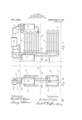
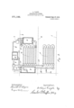
this method of producing the desired low temperatures is disadvantageous for the reason that the regulation of the quantity of ammonia used must be very nicely adjusted, since more or less than the desired quantity will be liable to escape from the regulating valve; In the present instance, the object is K portion throughout the several views, Figure l is a side elevation of tw'o sets of ammonia coils, Fig. 2 is an end elevation thereof, and Fig. 8 is a view partly in section of all of the separators used.
lit will be understood that while only a small number of coils has been illustrated, the number of coils may be increased indenitely, 3S desired. A l I Numeral l-represents' the i'rst iloor of a` buildingin which the vcoils are installed,v2
' the second door thereof, and 3 the upper Hoor thereof. vrlhe numeral 4 represents the up er set of coils, and the low'er set ot co1 s. rlhe upper set of eoils'is fed directly from the reservoir 6, in which is maintained liquid ammonia'at all times, the com ressorl 7. taking the gaseous ammonia' from t 8 leadmg from'the several sets ofjcoils.
Specicaton of Letters Patent.
Application filed December 10, 1909. Serial No. 532,518.
Patented Sept. 2'?, 219MB.
ammonia after leaving the compressor 7, passes into a condenser system 7. from which system, the liquid ammonia is delivered to the reservoir 6. The upper pipe of the coils 4 discharges int a large cylinder 9, an elbow 10 causing the liquid to pass into the bottom of said cylinder instead of into the return pipe l1, leadingto the pipe 8. The pipe 8 is also provided withl a separator 12,` which is in turn connected with the cylinder 9 by means of a pipe 13, so that any liquid which ma be carried over into the return pipe will e at once returned to the cooling coils. The bottom of the cylinder 9 isconnected by means of a pipe 14 with the lowest pipe of the coils 5, and the upper pipe of Y said /coils 5 is connected with a large pipe '15, said large pipe leading to the return pipe '8. Sincethe amount of ammonia used in the system may vvary considerably, an auxiliary pipe 16 is connected with the pipe 14 and the quantity of ammonia in thecoils 4 and 5 is thus kept up to the proper amount.
ltwill be understood by those skilled in the art thatV suitable valves. are placed throughout the System to control the low of ammonia therein.
In operation the coils 4 are fed with liquid ammonia, `and the fluid to be cooled is passed over them. Since the liquid ammonia is liquid only under very low temperatures un less under a very heavy pressure, it at once tends to form more or less gas, which latter passes out of the elbow 10 and into the se arator 9. Since the pipes 4 are kept floo ed with liquid ammonia, this will cause more or less of the Iliquid ammonia to Passoverinto the lower pipe system, and since the air or fluid to be cooled is passed overl that set of pipes as well, vmore or less gas forms 1n the fluid, and passes up through. the pipes 5 linto the large ipe 15, from which latter '1t is drawn to t ecoru ressor 7 then to the condenser coilsl7l' then to the reservoirv 6, to be ready for use again. Since there are wide changesv inthe temperatures of the substances passed ,over the coils 4 and 5, it sometimes happensthat considerable quantities of liquid ammoniamay even pass into the pi e 8, in which event the separator 1 2 will d1rect the liquid back tothe separator 'i 9, and from vthere it is ,returned to the coils 5. The quantity of liquid' ammonia in the pipes is determined by the'frost-line thereon. The advantage of this system of Huid cooling isthat it gasies no more of the ammonia than is actually needed, and it combines the method of liquid and gas cooling, and the large separators used prevent the iiooding of and injury to the ammonia coinpressor.
The amount of attention given the plant is reduced to a minimum for the reason that the total quantity of liquid ammonia used is never as great as the capacity of the pipes and separators.I Having thus described my invention, what I claim as new and desire to secure by Letters Patent of the United States is as follows:
l. In a refrigeration system, a series of coils, a condenser connected with said coils, a compressor discharging into said condenser and drawing from said coils, a liquid separator adaptedA to prevent liquids from passing from the coils into the compressor, a secondary set of coils so connected with said separator that it will receive any liquid deposited therein, a secondary separator interposed in the pipe line between the first separator and the compressor, and a pipe leading from the bottom of the secondary separator into the rst-named separator, substantially as set forth.
2. In a4 refrigeration system, a series of coils, a condenser connected With said coils, a liquid ammonia supply tank connected with said coils, a separator into Which said coils discharge, a secondary set of coils so connected with said separator that it Will receive any liquid deposited therein, a secondary liquid separator with which said secondary coils are connected, and a pipe connecting said secondary separator with a compressor, as set forth.
3. In a refrigeration system, a series of coils, a condenser, a compressor discharging into said condenser, a liquid ammonia supply tank connected with said coils, a separator into which saidfcoils discharge, a secondary set of'coils so connected with said separator that it will receive any liquid deposited therein, pipes connecting each of said sets of coils with the compressor, and a liquid separator in the pipe leading to the compressor, substantially 'as described.
4. In a. refrigeration system, a series of coils, la condenser, a compressor discharging into said condenser, va liquid ammonia supply tank connected with said coils and with 'said condenser, a separator into which said coils discharge, a secondaiy set of coils so connected With said separator that it Will receive any liquid deposited therein, pipes connecting each of said sets of coils with a compressor, a liquid separator-in the pipe leading to the compressor, and a pipe leading from the bottom of the last-mentioned 'separator into the first mentioned separator,
as set forth,
5. In a refrigeration system, a series. oi coils, a condenser, a compressor discharging into said condenser, a liquid ammonia supply tank connected with said coils, a separator into which said coils discharge, a secondary set of coils so connected with said separator that it Will receive any liquid deposited therein, pipes connecting each of said s ets of coils with the compressor, and a pipe leadingv from the bottom of the last-inentioned separator into the first mentioned separator, and means to regulate the quantity of the refrigerant supplied to the coils, substantially as described.
6. In a refrigeration system, a condenser, a compressor discharging into said condenser, a liquid ammonia supply, a set of defrigeration coils, a liquid separator into which said coils discharge, a secondary set of coils Y so connected with said separator that it yvill receive any liquid deposited therein, pipes connecting said sets of coils with the coinpressor, and an auxiliary liquid ammonia feed pipe connected With the secondary set of coils, substantially as set forth.
7. In a refrigeration system, a liquid ammonia supply, a set of refrigeration coils,
a condenser, a compressor discharging intoscribed Witnesses.
' ARTHUR FAGET. .Witnessesi W. MAoIMis,
' v C. P. Gramrin.
Priority Applications (1)
| Application Number | Priority Date | Filing Date | Title |
|---|---|---|---|
| US53251309A US971182A (en) | 1909-12-10 | 1909-12-10 | Refrigerating system. |
Applications Claiming Priority (1)
| Application Number | Priority Date | Filing Date | Title |
|---|---|---|---|
| US53251309A US971182A (en) | 1909-12-10 | 1909-12-10 | Refrigerating system. |
Publications (1)
| Publication Number | Publication Date |
|---|---|
| US971182A true US971182A (en) | 1910-09-27 |
Family
ID=3039568
Family Applications (1)
| Application Number | Title | Priority Date | Filing Date |
|---|---|---|---|
| US53251309A Expired - Lifetime US971182A (en) | 1909-12-10 | 1909-12-10 | Refrigerating system. |
Country Status (1)
| Country | Link |
|---|---|
| US (1) | US971182A (en) |
-
1909
- 1909-12-10 US US53251309A patent/US971182A/en not_active Expired - Lifetime
Similar Documents
| Publication | Publication Date | Title |
|---|---|---|
| JP2009263674A (en) | Apparatus for liquefying natural gas, and method relating to the same | |
| US2262519A (en) | Evaporator | |
| US971297A (en) | Art of treating air for use in metallurgical processes. | |
| US1024433A (en) | Accumulator and separator attachment for gas-liquefying apparatus. | |
| US1993478A (en) | Ejector control equipment | |
| US677845A (en) | Refrigeration system. | |
| US712704A (en) | Condenser for ammonia-gas. | |
| US757393A (en) | Refrigeration system. | |
| US406345A (en) | Refrigerative apparatus | |
| US313183A (en) | And andeew | |
| US1916197A (en) | Refrigerating apparatus | |
| US1174743A (en) | Separator. | |
| US1103386A (en) | Condenser. | |
| US1697342A (en) | Liquid-level or other fluid-flow regulator | |
| US890227A (en) | Apparatus for treating liquids. | |
| US436003A (en) | Process of circulating liquefied refrigerating agents | |
| US1387475A (en) | Evaporator control | |
| US747943A (en) | Generator for refrigerating apparatus. | |
| US510734A (en) | Albert f | |
| US2041659A (en) | Compressor | |
| US1200742A (en) | Refrigerating apparatus. | |
| US427765A (en) | Ice-machine and method of operating same | |
| US1272730A (en) | Condenser for refrigerating apparatus. | |
| US1146722A (en) | Condenser. | |
| JPH08312896A (en) | Liquefied gas evaporative gas treatment system and treatment method |