US971069A - Controlling-valve for fluid-operated motors. - Google Patents
Controlling-valve for fluid-operated motors. Download PDFInfo
- Publication number
- US971069A US971069A US48163209A US1909481632A US971069A US 971069 A US971069 A US 971069A US 48163209 A US48163209 A US 48163209A US 1909481632 A US1909481632 A US 1909481632A US 971069 A US971069 A US 971069A
- Authority
- US
- United States
- Prior art keywords
- valve
- low pressure
- pressure
- fluid
- delivery means
- Prior art date
- Legal status (The legal status is an assumption and is not a legal conclusion. Google has not performed a legal analysis and makes no representation as to the accuracy of the status listed.)
- Expired - Lifetime
Links
Images


Classifications
-
- F—MECHANICAL ENGINEERING; LIGHTING; HEATING; WEAPONS; BLASTING
- F25—REFRIGERATION OR COOLING; COMBINED HEATING AND REFRIGERATION SYSTEMS; HEAT PUMP SYSTEMS; MANUFACTURE OR STORAGE OF ICE; LIQUEFACTION SOLIDIFICATION OF GASES
- F25B—REFRIGERATION MACHINES, PLANTS OR SYSTEMS; COMBINED HEATING AND REFRIGERATION SYSTEMS; HEAT PUMP SYSTEMS
- F25B9/00—Compression machines, plants or systems, in which the refrigerant is air or other gas of low boiling point
- F25B9/14—Compression machines, plants or systems, in which the refrigerant is air or other gas of low boiling point characterised by the cycle used, e.g. Stirling cycle
- F25B9/145—Compression machines, plants or systems, in which the refrigerant is air or other gas of low boiling point characterised by the cycle used, e.g. Stirling cycle pulse-tube cycle
Definitions
- the object of the present invention is to provide an exhaust or. low pressure elastic fluid plant of the character above indicated reventing the ressure. at the stop valve 0%? or at the deivery point of. workin fluid to the low pressure element-from allin below apreetermined pressure while t e plant is in operation.
- the invention consists in a device auto-' matically acting independently of the gov? (higher pressure turbine, re-- an accumulator and a combined hig ernor to close the low pressure delivery means and thus to prevent the pressure in said delivery means from falling below a predetermined value or, in mixed pressure plant, so acting in conjunction with the governor that only the low pressure fluid supply is at any time under the influence of said device.
- umberland, En land have invented certain
- the invention also consists in a controlling device for performing the function referredto in the preceding'paragr'aphcombined with a sto valve, governor controlled low pressure va ve, trip gear, relay device or pufi' governing valve.
- Figure 1 is a vertical section of a valve according to this invention provided with means for holding it' to its seat when required.
- Fig. 2 is a vertical section of a valve similar to that shown in Fig. 1, but with a runaway controlling device attached to it.
- Fig. 3 is a vertical section of a modified form of the valve combined with a throttle valve operated directly 'by a governor.
- Fig.4 is a vertical section of a modified arrangement of valve combined with a governor operated throttle valve.
- Fig. 5 is 'a vertical section of an. arrangement in which a valve according to the invention is combined with and controlled by a steam relay -device. F'gs.
- FIG. 6 and 7 are cross sectional views on the l nes A A and B B of Fig. 5.
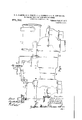
- Fig. 8 is a vertical section representing a modified arrangement of combined relay controllin devlce and valve according to the invention, while Fig. 9 shows a general arrangement of the a paratus shown in Fig. 3 as applied to an installation com rising pressure and low pressure. turbine.
- Aconvenient or steam reducing valve is shown in 1.
- the spindle, a, of the valve, 6, is connected to a diaphragm, 0, Which divides a chamber into two parts, (i and e, or which the top chamber, (Z, is in communication with the atmosphere and the under chamber, a, communicates freely by a pipe, f, or the like with the steam on the receiver or accumulator side, (3, of the reducing valve.
- "ldjustable spring means, g are provided which act directly onthe spindle or through a pivoted lever, b.
- valve in many cases it is desirable to enable the valve to be usedas a stop valve as Well as to be influenced by the pressure controlling device, this being effected by providing a separate screwed spindle i, to hold the valve 5i,
- the reducing device may be arranged in conjunction'with a runaway controlling device. (lne convenient way of effecting this is shown in 2 in which the construction or the reducing valve is substantially as described With reference to Fig. l, a balanced valve, Z), being connected wi h a c, or a piston.
- the valve be spring loaded but normally held open against the spring by the pressure of the c on the diaphragm.
- the initial tensi n o the springs, g g determines the a .llCll the valve operates. @n the un er si diaphragm, I
- low pressure throttle valve may be closed independently of the controlling governor when the pressure of the exhaust steam falls to a predetermined limi According to one method of carrying this into efiect as shown in Figs. 3 and 9 throttle valves g; and 5 admit the Working fluid to the low pressure and high pressure turbine elements and 24 respectively, the low pressure element 2 receiving its working fluid from an accumulator, G, into Which the steam exhausted from an independentand intermittently working steam engine or the like is delivered.
- the governor which controls the speed of both elements 23 and 2 2 is connected to the high pressure valve, 79, by a lever, a, which is connected by a link, 0, to another lever, 9, attached to the low pressure throttle valve, Z.
- the lever, g is pivot-ally attached to a member, r, carried by piston c, or diaphragm or the like, to thetop side or which steam from the receiver s e, C, of the low pressure valve is admitted, I other side being open to atmosphere; a suitable spring adjustment, g, is provided to enable theipres sure at which the valve will commence to close to be altered. in this arrangementthe low pressure valve is opened before the high pressure valve is opened.
- the lever, g, of the low pressure valve, 6, (see big. 4) isconnected to alink, s, which is pivoted to one end of a lever, t, with a fixed fulcrum at u, the other end of this lever, t, being connected to a spring pressed piston or diaphragm, o.
- the arrangement is such that if the exhaust pressure is not maintained at the turbine above a predetermined limit,'the plunger, w, falls and allows the fluid under the piston, Q), to escape and the spring moving the piston down, draws'the low pressure throttle valve, 6, into the closed position.
- the low I pressure throttle valve may be worked by a steam relay or by an oil or other suitable fluid-operated relay.
- of the above character is used its; exhaust chamber, 10, (Fig. 5) may be coupled to the condenser and the space, y, under the piston of it may be supplied with live or exhaust steam through a separate pipe, 2, and adjustable needle valve, 3, instead of by leakage through the gland as usually occurs.
- the reference 4 indicates the ordinary relay piston or plunger which is worked from the governor by the lever, 5.
- Anauxiliary plunger or valve, 6, is at one end attached to a diaphragm, 7, or to a piston, the underside of which is connected by a pipe, 22, to the exhaust steam supply and the other side of which is exposed to the atmosphere.
- the plungers and the pasmean a more or sages controlled by them are so arranged that when the exhaust steam pressure falls too low the steam under the piston, z, of the relay is allowed to escape through the passages, 8 and 9, annular space, 10, and ports,
- the pressure at which the valve or plunger, 6, will operate may be determined by adjusting springs, '12 and 13. In some cases or in each of the cases described hereinbei 'ore a cock, 21, is placed in the pipe, 22, so that the resistance may be varied by throttling the bore more or'less in order to prevent pulsation of the diaphragm. It.
- the low pressure valve closing device acts to prevent a drop of pressure entirelyindependently of the high pressure valve and 1 governor.
- the plunger .or valve, 6 in order. to prevent the loss of steam t-hrough'the underside of the relay piston which would occur when thethrottle .valve is closed, the plunger .or valve, 6, maybe made separate from the relay plunger but adapted to work in a similar manner to that described above.
- Such an arrangement is shown in Fig. 8, ports, 17 and 18, being provided in connection with the aforementioned plunger which may then cut ofi the supply of steam or other fluid to the rela cylinder when the throttle valve is close
- This device can be used either together with or independently of the relay plunger device described with reference to Figs. 5, 6 and 7 as obviously when the supply of steam to the under side of the relay piston falls the throttle valve will close.
- Fig. 8 the diaphra m, 7 is in its raised position the valve, 6, eing open and the annular space establishing communication between the supply (pipe, 15 and the ipe, 16, leading to the nee 1e valve; but w en the diaphragm deflects downward the plunger closes the supply pipe in consequence of which the piston and valve will fall, the latter being thereby closed u on its seat.
- a mixed flow tur ine installed'say at a colliery and having exhaust steam only when'thewinding lant is at work it would ess-serious loss to have steam flowing through therelay all night.
- an elastic fluid operated plant having a high pressure and a low pressure element, fluid delivery means to each of said elements, closing means within each of said delivery means, a device comprising an element responsive to changes of pressure within said low pressure delivery means, said device being connected to operate only the low pressure closing means to prevent a reduction in pressure below a predetermined amount from occurring within said low pressure deliveryv means.
- the device comprising a diaphragm subjected and responsive to changes of pressure within the low pressure delivery means. said device operating the low pressure valve inde pendently of its relay device whereby only the low pressure valve is closed to prevent a reduction of ressure below a predeter mined amount rom occurring. within said low pressure delivery means.
- a device connected to said closing means comprising in combination an element responsive to changes of pressure in said delivery means, means connected to said closing means for governing the speed of both of said elements, saiddevice operating said closing means without aflecting the high pressure element and independently of said governing means to prevent areduction in pressure below a predetermined amount from occurring in said low pressure delivery means.
- a device connected to the closing means in the low pressure delivery means comprising in combination an element' responsive to changes of pressure within said low pressure element, means connected with said closing means for governing the speed of both of said eleinents,said device operating only the low pressure closing means independently of said governing means to prevent a reducsaid device operates only the low pressure closing means independently of the govern ing means and without afl'ecting the high pressure closing means to prevent a reduction in pressure below apredetermined amount from occurring within said low pressure delivery means and on the speed of said elements exceeding a predetermined value the governing means release said trip means and cause the low pressuredelivery means to be closed.
- a device comprising a diaphragm'subjected and responsive to changes of pressure in said low pressure delivery means, a plunger carried by said diaphragm and controlling the admission of fluid operating the low pressure relay controlled valve,
- a low pressure throttle valve connected with a diaphragm on one side of which acts the fluid on the side of the valve toward which the fluid is moving, said diaphragm being adapted to operate only on the low pressure valve, a high pressure governorcontrolled throttle valve, differential lever means connecting the two valves and the diaphragm, some idle movement bein provided for in the connection of the di erential lever means in order that the low pressure valve may be moved by the governor independently of the high pressure valve.
- Controlling means for plant using elastic Working fluid and having a high pressure element and a lOW pressure element comprising a low pressure throttle valve and a high pressure throttle valve, a fluid operated spring pressed diaphragm a governorcontrolled system of diflerential levers connecting the two valves and said diaphragm a second diaphragm subjected on one side 20
- a fluid operated spring pressed diaphragm a governorcontrolled system of diflerential levers connecting the two valves and said diaphragm a second diaphragm subjected on one side 20
Landscapes
- Engineering & Computer Science (AREA)
- Physics & Mathematics (AREA)
- Mechanical Engineering (AREA)
- Thermal Sciences (AREA)
- General Engineering & Computer Science (AREA)
- Control Of Fluid Pressure (AREA)
Description
G. A. PARSONS, G. G. STONEY, A. Q. CARNEGIE & A. W. BOWERBANK. CONTROLLING VALVE FOR FLUID OPERATED MOTORS. APPLICATION FILED MAB. 6, 1909.
Q1 9 69 Patented Sept. 27, 1910.
. 7 SEEETS-SHEET 1.
[A/l E/v 70/257 UAW/7159424250; 55656.6 6:15 704 514 I flLFRED flnpmai/gz r W lMBaw/m O. A. PARSONS, G. G. STONEY, A. Q. CARNEGIE & A. W. BOWERBANK. CONTROLLING VALVE FOR FLUID OPERATED MOTORS. APPLIGATION FILED MAR. e, 1909'.
9?L6QL Eateated Sept 27, 1910.
7 8HEETS-SHEET 2.
(3, A. PARSONS, G. G. STONEY, A. Q. CARNEGIE & A. W. BOWERBANK. CONTROLLING VALVE FOR FLUID OPERATED MOTORS. APPLICATION FILED MAR. 6, 1909.
Patented .Sept 27, 1910.
4% MmQm K1 Arr C. A. PARSONS, G. G. STONEY, A. Q. CARNEGIE & A. W. BOWERBANK.
CONTROLLING VALVE FOR FLUID OPERATED MOTORS. APPLIOATION FILED MAB. 6, 1909.
' Patented Sept 27, 1910.
7 SHEETS-SHEET 4.
0. A. PARSONS, G. G. STONEY, A. Q. CARNEGIE & A. W. BOWERBANK. CONTROLLING VALVE FOR FLUID OPERATED MOTORS. APPLICATION FILED MAR. 6, 1909.
' Patented Sept 27, 1910.
7 SHEETS-SHEET 5.
g L I LQJ] m A 9 75 B I b H RX, 7
011494554 Bum /ls,
G. A. PARSONS, G. G. STONEY, A. Q. CARNEGIE & A. W. BOWERBANK.
CONTROLLING VALVE FOR FLUID OPERATED MOTORS. APPLICATION FILED MAR. 6, 1909.
9. Patented .Sept 27, 1910.
7 SHEETS-SHEET 6.
Hlll
[mum/MR5. CHAPL ESL i Pwsaws.
Game: G A ra/v51.
% dump Cm/vea/e flLBERT .Bawzx? Mr 0. A. PARSONS, G. G. STONBY, A. Q. CARNEGIE & A. W. BOWERBANK. CONTROLLING VALVE ron FLUID OPERATED MOTORS. APPLIOAHON FILED MAB. 6, 1909.
7 SHEETS-SHEET 7.
TTwMw.
Patented Sept. 27, 1910.
A ENT oioa.
CHAES ALGERNON PARSONS, GEORGE GERALD STONEY, ALIERED QUINTIN CAR- NEGIE, AND ALBERT WILLIAM BOWERBANK, OF NEWCASTLE-UPON-TYNE, ENG
LAND; SAID STONEY, CARNEGIE, AND BOZWERBANK ASSIGNORS TO SAID PARSONS.
CONTROLLING-VALVE FOR FLUID-OPERATED MOTORS.
canoes.
Specification of Letters Patent.
Patented Sept. 27, 1910.
Application filed March 6, 1909. Serial No. 481,832.
and Alumni WILLIAM BOWERBANK, all subects of .the King of Great Britain and Ireland, and residing at Heaton Works, Newcastle-upon-Tyn'e, in the county of Northnew and usefu Im rovements in Controlling-Valves for Fluid-Operated Motors, of which the following is a specification.
lhis invention relates to improvements.
sources, if the supply of exhaust or low pressure fluid falls off, or the supply of live uid be insufficient, it has hitherto been ossible, when the pressure of the working uid in the engine or. turbine becomes reduced, for a further reduction of pressure (which I may in a condensing plant even approach the vacuum'of the condenser) to occur in the receiver or accumulator or the like from which that engine or turbine receives its supply. This reduction of pressure or even a partial vacuum may occur at the exhaust of the motor ciprocating engine or the like) which delivers itsexhaust to the low pressure engine or turbine. This possibility under certain circumstances may lead to variations in the speed of the high pressure part of the plant or may introduce other difiiculties such as would hinder satisfactor operation and cause liability of ,air lea age with conse-- quent reduction of'vacunm in the condenser.
The object of the present invention is to provide an exhaust or. low pressure elastic fluid plant of the character above indicated reventing the ressure. at the stop valve 0%? or at the deivery point of. workin fluid to the low pressure element-from allin below apreetermined pressure while t e plant is in operation.
The invention consists in a device auto-' matically acting independently of the gov? (higher pressure turbine, re-- an accumulator and a combined hig ernor to close the low pressure delivery means and thus to prevent the pressure in said delivery means from falling below a predetermined value or, in mixed pressure plant, so acting in conjunction with the governor that only the low pressure fluid supply is at any time under the influence of said device. umberland, En land, have invented certain The invention also consists in a controlling device for performing the function referredto in the preceding'paragr'aphcombined with a sto valve, governor controlled low pressure va ve, trip gear, relay device or pufi' governing valve.
Referring now to the accompanying drawings: Figure 1 is a vertical section of a valve according to this invention provided with means for holding it' to its seat when required. Fig. 2 is a vertical section of a valve similar to that shown in Fig. 1, but with a runaway controlling device attached to it. Fig. 3 is a vertical section of a modified form of the valve combined with a throttle valve operated directly 'by a governor. Fig.4 is a vertical section of a modified arrangement of valve combined with a governor operated throttle valve. Fig. 5 is 'a vertical section of an. arrangement in which a valve according to the invention is combined with and controlled by a steam relay -device. F'gs. 6 and 7 are cross sectional views on the l nes A A and B B of Fig. 5. Fig. 8 is a vertical section representing a modified arrangement of combined relay controllin devlce and valve according to the invention, while Fig. 9 shows a general arrangement of the a paratus shown in Fig. 3 as applied to an installation com rising pressure and low pressure. turbine.
The direction of the flow of the main fluid through the valves is indicated on the draw- 1 r ay fluid by arrows numbered 2.
Incarrying this invention into eifect there isprovided in'the su ply pipe to the low pressure element a re ucmg valve which is so arranged that when the pressure at said low ressu're element dro 5 below a predetermmed amount, it shal close .or partly close and maintain atmospheric or some other predetermined pressure on the side of it which is toward the accumulator, receiver the diaphragm the low or exhaust of the higher pressure element which delivers steam or other elastic fluid to the low pressure element.
Aconvenient or steam reducing valve is shown in 1. The spindle, a, of the valve, 6, is connected to a diaphragm, 0, Which divides a chamber into two parts, (i and e, or which the top chamber, (Z, is in communication with the atmosphere and the under chamber, a, communicates freely by a pipe, f, or the like with the steam on the receiver or accumulator side, (3, of the reducing valve. "ldjustable spring means, g, are provided which act directly onthe spindle or through a pivoted lever, b.
When a normal pressure above atmosphere is to he maintai ed the accumulator side, C, of the valv c springs, g, tend to press the valve d its seat so long as illQPIQSSXllG on underside the diaphragm amount deter mined by the adjustment or the springs or the area of the diaphragm the valve remains open, but when the pressure falls belovv the normal the s rin closes the valve more or less or entire y, thereby preventing any undue reduction of pressure the supply side of the valve, no matter how low below the normal thepressure may be on the other side of the valve. it will be obvious of course that if at C a normal absolute pressure be required which is somewhat belovv atmospheric, the springs must tend to hold thevalve normally opened against the difference of pressure acti g upon the top of the diaphragm; pressure falls belovv the normal the valve will close or partially close against the resistance of the springs. v
in many cases it is desirable to enable the valve to be usedas a stop valve as Well as to be influenced by the pressure controlling device, this being effected by providing a separate screwed spindle i, to hold the valve 5i,
firmly on its seat when necessary.
it will be readily seen that the mechanical features of the device may be varied vary considerably Without departing from the invention ;v for example the diaphragm may be replaced by a piston working in a cylinder.
The reducing device may be arranged in conjunction'with a runaway controlling device. (lne convenient way of effecting this is shown in 2 in which the construction or the reducing valve is substantially as described With reference to Fig. l, a balanced valve, Z), being connected wi h a c, or a piston. The valve be spring loaded but normally held open against the spring by the pressure of the c on the diaphragm. The initial tensi n o the springs, g g, determines the a .llCll the valve operates. @n the un er si diaphragm, I
pressure steam v acts but the other side is open to atmospheric pressure. Ir" the pressure on the diaphragm falls, due to the partial vacuum or reduced pressure Working backward, the valve Will partially or entirely close. In engagement with the spindle there is also arranged one end or a lever, j, which is pivoted at it, the other end of the lever being normally held down against the resistance of a spring, at, by means of trip levers or the like under the control of a governor.
hen the speed of the governor exceeds a predetermined amount, the trip mechanism is released and the spring, m, acting freely on the lever, thrusts the valve to its seat and prevents further passage of steam to the pressure element. r m auxiliar hand controlling element, 2', he also provided i r closing the valve when required, as described with reference to It.
will seen that in both Figs. 1 the device is not under the influence governor nor is the governor afiected by it, but in the event of the speed of the motor becoming much too high the runaway governor (in Fig. 2) releases the trip mechanism which allows the spring, m, of the device to close the valve. In other cases the device and 2,
may be combined With a higher pressure throttle valve Worked direct from the governor, the arrangement being such that by means of a differential system of levers, the
low pressure throttle valve may be closed independently of the controlling governor when the pressure of the exhaust steam falls to a predetermined limi According to one method of carrying this into efiect as shown in Figs. 3 and 9 throttle valves g; and 5 admit the Working fluid to the low pressure and high pressure turbine elements and 24 respectively, the low pressure element 2 receiving its working fluid from an accumulator, G, into Which the steam exhausted from an independentand intermittently working steam engine or the like is delivered. The governor which controls the speed of both elements 23 and 2 2 is connected to the high pressure valve, 79, by a lever, a, which is connected by a link, 0, to another lever, 9, attached to the low pressure throttle valve, Z. The lever, g, is pivot-ally attached to a member, r, carried by piston c, or diaphragm or the like, to thetop side or which steam from the receiver s e, C, of the low pressure valve is admitted, I other side being open to atmosphere; a suitable spring adjustment, g, is provided to enable theipres sure at which the valve will commence to close to be altered. in this arrangementthe low pressure valve is opened before the high pressure valve is opened. it the governor comes into action the high pressure valve closes first and then the low pressure valve, certain movements 20, being provided in connection the lever, to, with of the poi spindle of the high pressure valve, 7), but, in all'cases when the receiver pressure drops, the low pressure valve is closed, and it will be noted that on account of the idle movement above mentioned the closure of this low pressure valve is efl'ected by the piston, (z, entirelyindependently-of the governor or other controlling element and without affecting the high pressure valve.
In a modification of the arrangement last described the lever, g, of the low pressure valve, 6, (see big. 4) isconnected to alink, s, which is pivoted to one end of a lever, t, with a fixed fulcrum at u, the other end of this lever, t, being connected to a spring pressed piston or diaphragm, o. On the underside 'of'the piston, steam, oil or other fluid is admitted and this oil is prevented from escaping by means of a plunger valve, w, or like device operated by a diaphragm or piston, w,'having exhaust steam on one side and atmospheric pressure on the other. The arrangement is such that if the exhaust pressure is not maintained at the turbine above a predetermined limit,'the plunger, w, falls and allows the fluid under the piston, Q), to escape and the spring moving the piston down, draws'the low pressure throttle valve, 6, into the closed position.
It will be noticed that in all these devices when combined with governor controlling meansithe action-of the governor is first to open the low pressure valve until a point is reached where either the supply of exhaust steam is insuflicient for the load or the pressure is not sufficient and then, when the low pressure valve is fully open, the governor begins to open the high pressure valve; but if the pressure in the receiver falls below the predetermined pressure the devices then close the low pressure valve so as to prevent the vacuum getting. back into the receiver,
but the governor or high pressure valve controlling element is, not many way affected,
In a further modification of the invention the low I pressure throttle valve may be worked by a steam relay or by an oil or other suitable fluid-operated relay. Where 'a steam relay| of the above character is used its; exhaust chamber, 10, (Fig. 5) may be coupled to the condenser and the space, y, under the piston of it may be supplied with live or exhaust steam through a separate pipe, 2, and adjustable needle valve, 3, instead of by leakage through the gland as usually occurs. In Fig. 5 the reference 4 indicates the ordinary relay piston or plunger which is worked from the governor by the lever, 5. Anauxiliary plunger or valve, 6, is at one end attached to a diaphragm, 7, or to a piston, the underside of which is connected by a pipe, 22, to the exhaust steam supply and the other side of which is exposed to the atmosphere. As will be seen from the figures the plungers and the pasmean a more or sages controlled by them are so arranged that when the exhaust steam pressure falls too low the steam under the piston, z, of the relay is allowed to escape through the passages, 8 and 9, annular space, 10, and ports,
11, into the chamber, 14, which as above stated may be coupled to the condenser; the throttle valve, 6, is thus partially closed so as to maintain the required pressure or it may be completely closed.
The pressure at which the valve or plunger, 6, will operate may be determined by adjusting springs, '12 and 13. In some cases or in each of the cases described hereinbei 'ore a cock, 21, is placed in the pipe, 22, so that the resistance may be varied by throttling the bore more or'less in order to prevent pulsation of the diaphragm. It.
will be observed that according to this 'arrangement as also according toFigs. 1 and 2, the low pressure valve closing device acts to prevent a drop of pressure entirelyindependently of the high pressure valve and 1 governor.
In a modification of the device last described, in order. to prevent the loss of steam t-hrough'the underside of the relay piston which would occur when thethrottle .valve is closed, the plunger .or valve, 6, maybe made separate from the relay plunger but adapted to work in a similar manner to that described above. Such an arrangement is shown in Fig. 8, ports, 17 and 18, being provided in connection with the aforementioned plunger which may then cut ofi the supply of steam or other fluid to the rela cylinder when the throttle valve is close This device can be used either together with or independently of the relay plunger device described with reference to Figs. 5, 6 and 7 as obviously when the supply of steam to the under side of the relay piston falls the throttle valve will close.
In Fig. 8 the diaphra m, 7 is in its raised position the valve, 6, eing open and the annular space establishing communication between the supply (pipe, 15 and the ipe, 16, leading to the nee 1e valve; but w en the diaphragm deflects downward the plunger closes the supply pipe in consequence of which the piston and valve will fall, the latter being thereby closed u on its seat. In the case of a mixed flow tur ine installed'say at a colliery and having exhaust steam only when'thewinding lant is at work, it would ess-serious loss to have steam flowing through therelay all night.
Although we have generally described the above invention in connection with a mixed flow turbine or one taking steam at two different pressures the same is applicable to any type of turbine taking steam at one.
pressure only when it is desired. to prevent the pressure at the inlet of the turbine falling below a predetermined amount.
Having now described our invention what 'we claim as new and desire to secure by Letters Patent is:
1. In an elastic fluid operated plant hav' ing a high pressure and a low pressure element, fluid delivery means to said low pres sure element, closing means within said delivery means, a device comprising an element responsive to changes of pressure within said low pressure delivery means, said device being connected to said closing means and operating the same without atfecting the high pressure element to prevent a reduction in pressure below a predetermined amount from occurring within said low. pressure delivery means.
2. In an elastic fluid operated plant having a high pressure and a low pressure element, fluid delivery means to each of said elements, closing means within each of said delivery means, a device comprising an element responsive to changes of pressure within said low pressure delivery means, said device being connected to operate only the low pressure closing means to prevent a reduction in pressure below a predetermined amount from occurring within said low pressure deliveryv means.
3. In combination in an elastic fluid oper-. ated plant having a low pressure element, fluid delivery means to said element, a relay controlled valve in said delivery means, a device subjected and responsive to chan es of pressure in said delivery means, said evice operating said valve independently of the relay device, whereby said low pressure valve is closed to prevent a reduction in pressure below a predetermined amount from occurring in said low pressure delivery means.
4. In combination in an elastic fluid operated plant having a high pressure and a low pressure element, fluid delivery means to each of said elements, a relay controlled valve in the low pressure delivery means, a"
device comprising a diaphragm subjected and responsive to changes of pressure within the low pressure delivery means. said device operating the low pressure valve inde pendently of its relay device whereby only the low pressure valve is closed to prevent a reduction of ressure below a predeter mined amount rom occurring. within said low pressure delivery means.
5. In combination in an elastic fluid operated plant having a low pressure element, fluid delivery means to said element, governing means to control the speed of said element, a relay controlledvalve in said delivery means, a device subjected'and responsive to changes of pressure in said delivery means, said device operatin said valve independently of thefrelay device, whereby said low pressure .valve is automatically closed independently of the governing means and without affecting the high pressure eleing a diaphragm subjected and responsive to changes of pressure in said delivery means, said device operating said val e independently of the relay device whereby said low pressure valve is automatically closed independently of the governing means and without 'aflecting the high pressure element to. prevent a reduction in pressure below a predetermined amount from occurring within the low pressure delivery means. 7
7. In an elastic fluid operated plant having a high pressure and a low pressure element, fluid delivery meansto said low pressure element, closing means within said delivery means, a device connected to said closing means comprising in combination an element responsive to changes of pressure in said delivery means, means connected with said closing means for governing the speed of said low pressure element, said device operating said closing means without affecting the high pressure element and independently oi said governing means to prevent a reduction in pressure below a predetermined amount from occurring in said low pressure delivery means.
8. In an elastic fluid operated plant having a high pressure and a low pressure element, fluid delivery means to said low pressure element, closing means Within said delivery mean's, a device connected to said closing means comprising in combination an element responsive to changes of pressure in said delivery means, means connected to said closing means for governing the speed of both of said elements, saiddevice operating said closing means without aflecting the high pressure element and independently of said governing means to prevent areduction in pressure below a predetermined amount from occurring in said low pressure delivery means.
9. In an elastic fluid operated plantv having a high pressure and a low pressure element, fluid deliverymeans to each of said elements, closing means within each of said delivery means, a device. connected to the closing means in the low pressure delivery means comprising in combination an element' responsive to changes of pressure within said low pressure element, means connected with said closing means for governing the speed of both of said eleinents,said device operating only the low pressure closing means independently of said governing means to prevent a reducsaid device operates only the low pressure closing means independently of the govern ing means and without afl'ecting the high pressure closing means to prevent a reduction in pressure below apredetermined amount from occurring within said low pressure delivery means and on the speed of said elements exceeding a predetermined value the governing means release said trip means and cause the low pressuredelivery means to be closed. j
11. In combination in a fluid operated plant having a high pressure and a low pressure element, fluid delivery means to 0' said device operating the low pressure clossaid low pressure element, closing means within sa d delivery means, a device connected to said closing means comprising an :elementresponsive to changes of pressure in said low pressure delivery means, means .governing the speed of said low pressure element, trip levers connecting said governing means and low pressure closing means,
ing means without affecting the high pres- 1 sure element and independently-of said governing means to prevent a reduction of pressure below a predetermined. amount from occurring within said low pressure delivery means.
12'. In combination "in a fluid operated plant having a high pressure and a lowplant having a high pressure and a low pressure element, fluid delivery means to said low pressure element, a valve controlling the flow of fluid in said delivery means, speed governing means .for said low pressure element, a device acting automatically and independently of, the governing means to close the valve in said low pressure delivery means without aifecting the high pressure element and prevent a reduction in pressure below a predetermined amount from'occurl ring in said low pressure element.
14. In combination in a fluid operated plant having a high pressure and a low pressure element, fluid delivery means to said low pressure element, closing means within said delivery means, a device connected to said closing means comprising an element responsive to changes of pressure in said low pressure delivery means, means governing the speed of said low pressure element, trip leVers cOnnecting said governing means and low pressure closing means, said device operating the low pressure closing means without affecting the high pressure element and independently of said governing means to prevent a reduction of-pressure below a predetermined amount from occurring within said low pressure delivery means and on a change of speed of said low pressure element said governing means acts independ-. ently of said device to close the low pressure valve.
15. In combination in an elastic fluid operated'plant having a high pressure and a low pressure element, fluid delivery means to each of said elements, a valve in each of said deliver means, means controlling the speed of sai elements and connected to each of said valves, a device comprising a diaphragm subjected and responsive to changes of fluid pressurein said low pressure delivery means, connections between said device and the low pressure valve, said device acting automatically and independently of said governing means to close said low pressure valve and prevent a reduction ofpressure -below a predetermined amount in the low pressure delivery means without afl'ecting the high pressure valve.
16. In an elastic fluid operated plant having a high pressure and a low pressure element, fluid delivery means to each of said elements, a relay operated valve in the low pressure fluid delivery means, a valve in the high pressure delivery means, means governing the speed of said elements and connected -to said valves, a device. comprising a diaphragm'subjected and responsive to changes of pressure in said low pressure delivery means, a plunger carried by said diaphragm and controlling the admission of fluid operating the low pressure relay controlled valve,
whereby on a reduction of pressure in the low pressure delivery means said diaphragm operates sa'id low pressure valve without aflecting the high pressure valve.
17. Controlling means for plant us ng elastic working fluid and having a hlgh vpressure element and a low pressure element,
comprising a low pressure throttle valve connected with a diaphragm on one side of which acts the fluid on the side of the valve toward which the fluid is moving, said diaphragm being adapted to operate only on the low pressure valve, a high pressure governorcontrolled throttle valve, differential lever means connecting the two valves and the diaphragm, some idle movement bein provided for in the connection of the di erential lever means in order that the low pressure valve may be moved by the governor independently of the high pressure valve.
18. Controlling means for plant using elastic Working fluid and having a high pressure element and a lOW pressure element, comprising a low pressure throttle valve and a high pressure throttle valve, a fluid operated spring pressed diaphragm a governorcontrolled system of diflerential levers connecting the two valves and said diaphragm a second diaphragm subjected on one side 20 In testimony whereof, We aflix our signa- 5 tures in presence of two Witnesses.
CHARLES ALGERNON PARSONS. GEORGE GERALD STONEY. ALFRED QUINTIN CARNEGIE. ALBERT WILLIAM BOWERBANK.
Witnesses:
HENRY GRAHAM DAHYM, J r., FREDERICK GORDON HAY BEDFORD.
Priority Applications (1)
| Application Number | Priority Date | Filing Date | Title |
|---|---|---|---|
| US48163209A US971069A (en) | 1909-03-06 | 1909-03-06 | Controlling-valve for fluid-operated motors. |
Applications Claiming Priority (1)
| Application Number | Priority Date | Filing Date | Title |
|---|---|---|---|
| US48163209A US971069A (en) | 1909-03-06 | 1909-03-06 | Controlling-valve for fluid-operated motors. |
Publications (1)
| Publication Number | Publication Date |
|---|---|
| US971069A true US971069A (en) | 1910-09-27 |
Family
ID=3039455
Family Applications (1)
| Application Number | Title | Priority Date | Filing Date |
|---|---|---|---|
| US48163209A Expired - Lifetime US971069A (en) | 1909-03-06 | 1909-03-06 | Controlling-valve for fluid-operated motors. |
Country Status (1)
| Country | Link |
|---|---|
| US (1) | US971069A (en) |
-
1909
- 1909-03-06 US US48163209A patent/US971069A/en not_active Expired - Lifetime
Similar Documents
| Publication | Publication Date | Title |
|---|---|---|
| US2764868A (en) | Servo control of internal combustion prime movers by blower pressure | |
| US2622611A (en) | Pressure regulator | |
| US2624980A (en) | Pilot operated fluid pressure regulator | |
| US971069A (en) | Controlling-valve for fluid-operated motors. | |
| US3526091A (en) | Control apparatus for equalizing and/or limiting an engine operating condition of a plurality of gas turbine engines | |
| US2670598A (en) | Gas turbine plant with multiple fluid operated motors | |
| US2649686A (en) | Apparatus for controlling the supply of liquid fuel to the combustion chambers of prime movers | |
| US3219309A (en) | Pressure ratio device | |
| US3293847A (en) | Coordinated main and afterburner fuel controls for gas turbine engines | |
| US2991002A (en) | Installations for compressing air or gas | |
| US3060686A (en) | Augmented gas turbine engine and controls | |
| US2851230A (en) | Mach number responsive control for aircraft fuel system | |
| US3121456A (en) | Gas turbine fuel system | |
| US2705017A (en) | Counterbalanced fluid-relay mechanism | |
| US2009418A (en) | Back pressure control mechanism | |
| US3244190A (en) | Pneumatic relay valve | |
| US3596669A (en) | Pressure ratio device | |
| US2657529A (en) | Means for controlling the supply of liquid fuel to combustion prime movers | |
| US2207941A (en) | Pressure regulation | |
| US1136211A (en) | Boiler-cut-off system. | |
| US912503A (en) | So-called reducing-valve. | |
| US1109168A (en) | Power system. | |
| US1141983A (en) | Power-generating system. | |
| US991647A (en) | Air-pump governor. | |
| US3075351A (en) | Control for hydraulic servo-actuated apparatus |