US9706480B2 - Method for determining cell identification information - Google Patents
Method for determining cell identification information Download PDFInfo
- Publication number
- US9706480B2 US9706480B2 US13/851,163 US201313851163A US9706480B2 US 9706480 B2 US9706480 B2 US 9706480B2 US 201313851163 A US201313851163 A US 201313851163A US 9706480 B2 US9706480 B2 US 9706480B2
- Authority
- US
- United States
- Prior art keywords
- cell
- identification information
- time
- signal
- reference signals
- Prior art date
- Legal status (The legal status is an assumption and is not a legal conclusion. Google has not performed a legal analysis and makes no representation as to the accuracy of the status listed.)
- Expired - Fee Related, expires
Links
Images


Classifications
-
- H—ELECTRICITY
- H04—ELECTRIC COMMUNICATION TECHNIQUE
- H04W—WIRELESS COMMUNICATION NETWORKS
- H04W48/00—Access restriction; Network selection; Access point selection
- H04W48/16—Discovering, processing access restriction or access information
-
- H—ELECTRICITY
- H04—ELECTRIC COMMUNICATION TECHNIQUE
- H04L—TRANSMISSION OF DIGITAL INFORMATION, e.g. TELEGRAPHIC COMMUNICATION
- H04L5/00—Arrangements affording multiple use of the transmission path
- H04L5/003—Arrangements for allocating sub-channels of the transmission path
- H04L5/0053—Allocation of signalling, i.e. of overhead other than pilot signals
-
- H—ELECTRICITY
- H04—ELECTRIC COMMUNICATION TECHNIQUE
- H04L—TRANSMISSION OF DIGITAL INFORMATION, e.g. TELEGRAPHIC COMMUNICATION
- H04L5/00—Arrangements affording multiple use of the transmission path
- H04L5/0001—Arrangements for dividing the transmission path
- H04L5/0003—Two-dimensional division
- H04L5/0005—Time-frequency
- H04L5/0007—Time-frequency the frequencies being orthogonal, e.g. OFDM(A) or DMT
Definitions
- the disclosure relates to methods for determining cell identification information and to methods for verifying cell identification information.
- the disclosure further relates to devices to perform such methods.
- Ghost cell detection may be an issue caused by a cell search.
- a main task of a cell search may be to find the strongest cell Ids and place them in an ordered cell list. In an acquisition phase, the strongest cell may be chosen to establish the data link. Other strong cells may be further tracked in order to enable a fast cell handover by the UE (User Equipment).
- UE User Equipment
- a basic problem may occur when the cell search peaks suggest detected cells, which are actually not synchronized at the proposed frame position or not existing at all. These wrongly detected cells may be called “ghost cells”. If the UE assumes a detected ghost cell is a valid cell and initiates further acquisition procedures, it may be dropped by the network. Thus, additional processing may be required to ensure that a cell search only detects valid cells. It may be desirable to find a way to differentiate between true cells and ghost cells.
- FIG. 1 is a schematic diagram of a method 100 in accordance with the disclosure for determining cell identification information.
- FIG. 2 is a schematic diagram of a device 200 in accordance with the disclosure for providing cell identification information.
- FIG. 3 is a schematic diagram of a method 300 in accordance with the disclosure for verifying cell identification information.
- FIG. 4 is a schematic time-frequency representation of two example sub-frames 400 of a radio frame including reference signals R 0 used for determining cell identification information.
- FIG. 5 is a schematic diagram of a method 500 in accordance with the disclosure for differentiating between true cells and ghost cells.
- FIG. 6 is a schematic diagram 600 of a correlation signal 601 based on a PSS cell search and time-domain signals 602 , 603 , 604 based on a CRS cell search.
- FIG. 7 a is an example ghost cell simulation diagram 700 a illustrating a case of false detection of PSS 1 for an AWGN channel resulting in a “ghost” PSS 1 peak 701 a.
- FIG. 7 b is an example ghost cell simulation diagram 700 b illustrating a case of false detection of PSS 1 for an EPA 5 Hz channel resulting in a “ghost” PSS 1 peak 701 b.
- FIG. 7 c is an example ghost cell simulation diagram 700 c illustrating a case of false detection of PSS 1 for an ETU 70 Hz channel resulting in a “ghost” PSS 1 peak 701 c.
- FIG. 7 d is an example ghost cell simulation diagram 700 d illustrating a case of false detection of PSS 1 for an EVA 70 Hz channel resulting in a “ghost” PSS 1 peak 701 d.
- FIG. 7 e is an example ghost cell simulation diagram 700 e illustrating a case of false detection of PSS 1 for an ETU 300 Hz channel resulting in a “ghost” PSS 1 peak 701 e.
- PSS Primary Synchronization Signal
- LTE Long Term Evolution
- UE User Equipment
- PRB Physical Resource Block
- OFDM Orthogonal Frequency Division Multiplex
- CRS Cell-specific Reference Signal
- eNodeB E-UTRAN Node B, also known as Evolved Node B, (abbreviated as eNodeB or eNB) is the element in E-UTRA of LTE that is the evolution of the element Node B in UTRA of UMTS.
- the methods and devices described herein may be based on two-dimensional signal patterns, reference signals and frequency-time transforms of reference signals. It is understood that comments made in connection with a described method may also hold true for a corresponding device configured to perform the method and vice versa. For example, if a specific method act is described, a corresponding device may include a unit to perform the described method act, even if such a unit is not explicitly described or illustrated in the figures. Further, it is understood that the features of the various example aspects described herein may be combined with each other, unless specifically noted otherwise.
- the methods and devices described herein may be implemented in wireless communication networks, in particular communication networks based on an LTE and/or OFDM standard.
- the methods and devices described below may further be implemented in a mobile device (or mobile station or User Equipment (UE)).
- the described devices may include integrated circuits and/or passives and may be manufactured according to various technologies.
- the circuits may be designed as logic integrated circuits, analog integrated circuits, mixed signal integrated circuits, optical circuits, memory circuits and/or integrated passives.
- Radio signals may be or may include radio frequency signals radiated by a radio transmitting device (or radio transmitter or sender) with a radio frequency lying in a range of about 3 Hz to 300 GHz.
- the frequency range may correspond to frequencies of alternating current electrical signals used to produce and detect radio waves.
- LTE Long Term Evolution
- 4G LTE Long Term Evolution
- 3GPP 3rd Generation Partnership Project
- OFDM Orthogonal Frequency-Division multiplexing
- OFDM is a scheme for encoding digital data on multiple carrier frequencies.
- OFDM has developed into a popular scheme for wideband digital communication, whether wireless or over copper wires, used in applications such as digital television and audio broadcasting, DSL broadband internet access, wireless networks, and 4G mobile communications.
- OFDM is a Frequency-Division Multiplexing (FDM) scheme used as a digital multi-carrier modulation method.
- FDM Frequency-Division Multiplexing
- a large number of closely spaced orthogonal sub-carrier signals may be used to carry data.
- the orthogonality may prevent crosstalk between sub-carriers.
- the data may be divided into several parallel data streams or channels, one for each sub-carrier.
- Each sub-carrier may be modulated with a conventional modulation scheme (such as quadrature amplitude modulation or phase-shift keying) at a low symbol rate, maintaining total data rates similar to conventional single-carrier modulation schemes in the same bandwidth.
- OFDM may be essentially identical to Coded OFDM (COFDM) and Discrete Multi-Tone modulation (DMT).
- the methods and devices described herein may be based on a PSS/CSS cell search described in the following.
- LTE the system synchronization is usually first accomplished in downlink (DL) and then in uplink (UL).
- the User Equipment (UE) may perform an initial time and frequency offset estimation by detecting synchronization signals of base stations or eNodeBs. When this estimation is successfully performed, the UE can acquire the frame structure of the DL signal, and read basic system information, e.g. cell identity (cell ID), DL bandwidth, etc.
- cell ID cell identity
- the information on Ns and Ng may be carried by two DL synchronization channels of an eNB, that may be the primary synchronization channel (P-SCH) signal (PSS) and the secondary synchronization channel (S-SCH) signal (SSS), respectively.
- P-SCH primary synchronization channel
- S-SCH secondary synchronization channel
- the PSS may be embedded in the last OFDM symbol and the SSS in the second last OFDM symbol of the subframe 0 and 5 in each radio frame.
- the P-SCH signal may consist of three length-62 Zadoff-Chu sequences in frequency domain which are orthogonal to each other. Each sequence may correspond to a sector identity Ns within a group of three sectors (physical cell).
- the S-SCH signal may consist of a frequency-domain sequence d(n) with the same length as the P-SCH, which is an interleaved concatenation of the two length-31 binary sequences s 0 ( n ) and s 1 ( n ).
- s 0 ( n ) and s 1 ( n ) may depend on a pair of integers m 0 and m 1 , which may be unique for each group-ID Ng.
- a cross-correlation of the received symbols on the 62 centered sub-carriers with replicas of the three P-SCH signals in the frequency domain may be performed.
- the magnitude of the cross correlator output corresponding to the sector with the highest signal may show a large peak compared to the other correlation terms due to orthogonality between sequences.
- the estimated sector-ID Ns may be given by that maximum.
- the sector identification may indicate the radio frame start, as the P-SCH position within the radio frame is already known, however with an uncertainty between the first and sixth sub-frame. This information may be retrieved by decoding the S-SCH signal.
- the group-ID Ng can be jointly estimated with the carrier frequency offset and the sub-frame index within the radio frame (0 or 5).
- the basic concept may be to exploit the cyclic shifts of the two length-31 binary sequences s 0 ( n ) and s 1 ( n ) according to the pair of integers m 0 and m 1 , which identify the group-ID.
- Cell-specific reference sequences may consist of complex-valued entries derived from a pseudo random sequence which may be generated by a length-31 Gold sequence, the state of which may be initialized by an initialization value at the beginning of each OFDM symbol.
- the initializing value may depend on the cell ID Nc.
- the cell-specific reference sequences thus may be unique for each slot, OFDM symbol and cell index, and as well depend on the cyclic prefix type.
- the sequence elements may be mapped on the time-frequency resource grid on every sixth sub-carrier within two OFDM symbols in every slot.
- resource elements used for the reference signal transmission shall not be used for transmission on any other antenna in the same slot and thus may be set to zero.
- An example for the allocation of the reference sequences within the resource grid is illustrated in FIG. 4 as described below.
- FIG. 1 is a schematic diagram of a method 100 in accordance with the disclosure for determining cell identification information.
- the method 100 includes receiving a signal including a two-dimensional signal pattern in a time-frequency representation at 101 .
- the two-dimensional signal pattern includes reference signals at first predetermined positions in the two-dimensional signal pattern.
- the method 100 further includes determining a frequency-time transformation based on the reference signals to obtain a time-domain signal at 103 .
- the method 100 further includes determining a first cell identification information based on a threshold criterion with respect to the time-domain signal at 105 .
- the reference signals may include the cell identification information, and the cell identification information may be unique for each cell of a cellular radio system.
- the reference signals may include cell-specific reference signals.
- the frequency-time transformation may include an Inverse Fast Fourier Transform (IFFT), a Fast Fourier Transform (FFT), an Inverse Discrete Fourier Transform or a Discrete Fourier Transform.
- IFFT Inverse Fast Fourier Transform
- FFT Fast Fourier Transform
- Discrete Fourier Transform a Discrete Fourier Transform
- the received signal may include a superposition of a signal received from a target cell of a cellular radio system and a signal received from an interfering cell of the cellular radio system.
- the method 100 may include using the first cell identification information for verifying a second cell identification information determined based on a synchronization signal positioned at a second predetermined position in the two-dimensional signal pattern different from the first predetermined positions in the two-dimensional signal pattern.
- the synchronization signal may include a primary synchronization signal and/or a secondary synchronization signal.
- the second cell identification information may be determined based on a second threshold criterion with respect to a correlation of the synchronization signal in the time domain.
- a bandwidth of the synchronization signal may be smaller than a bandwidth of the reference signals. The higher bandwidth corresponds to better timing accuracy.
- the timing accuracy i.e., the misalignment of corresponding peaks of the first and second signal is below a cyclic prefix (CP).
- the method 100 provides a time accuracy better than a cyclic prefix (CP) based processing because any operation on the two-dimensional signal pattern, i.e. the time-frequency grid, would have a timing accuracy below the cyclic prefix.
- a number of frequency-domain samples of the synchronization signal may be smaller than a number of frequency-domain samples of the reference signals.
- a correlation of the synchronization signal in time domain provides independent information from the frequency-time transformation based on the reference signals.
- An example of the method 100 may apply IFFT processing on the RS.
- the RS may be modulated by m-sequences that may be defined by the cell ID and time position of the RS symbol.
- the RS resource elements (REs) may be located with a predefined time and subcarrier spacing within the LTE time-frequency grid. Therefore, the IFFT output may be an under- or re-sampled version of the channel impulse response (CIR) sampled according to the configured UE bandwidth. Since the PSS/SSS may provide the slot (half subframe) and radio frame timing, the IFFT processing may resolve the fine timing defined by the minimum RS subcarriers spacing.
- the IFFT processing may be used to discover the CIR echo paths as can be seen from FIG. 6 described below. These echo peaks may only occur in a defined capture range in the correct OFDM frame. Cell identification information can be derived from these CIR peaks. As described above, the cell-specific reference signals carry cell ID information. That cell ID information can be extracted by evaluating the sample index where the CIR peaks occur.
- FIG. 2 is a schematic diagram of a device 200 in accordance with the disclosure for providing cell identification information.
- the device 200 includes a first unit 201 , a second unit 203 and a third unit 203 .
- the first unit 201 receives a receive signal 210 including a two-dimensional signal pattern in a time-frequency representation.
- the two-dimensional signal pattern includes reference signals at predetermined positions in the two-dimensional signal pattern, e.g. reference signals R 0 according to the representation of FIG. 4 described below.
- the second unit 203 determines a frequency-time transformation, e.g. a IFFT, FFT, IDFT or DFT, based on the reference signals to obtain a time-domain signal 214 .
- the third unit 205 provides a cell identification information 216 based on a threshold criterion with respect to the time-domain signal 214 .
- the first unit 201 , second unit 203 and third unit 203 may be hardware units implemented in a chip.
- the first unit 201 , second unit 203 and third unit 203 may also be implemented as software on a computer.
- the first unit 201 , second unit 203 and third unit 203 may also be implemented as processing circuits, e.g. application specific integrated circuits (ASICs) on a processor, e.g. a digital signal processor (DSP).
- ASICs application specific integrated circuits
- DSP digital signal processor
- the first unit 201 may represent a receiver circuit and the second and third units 203 , 205 may represent processing circuits.
- the device 200 may include a chip, and the device 200 may be part of a mobile device.
- the received signal may include an orthogonal frequency division multiplex signal, e.g. according to the representation of FIG. 4 .
- FIG. 3 is a schematic diagram of a method 300 in accordance with the disclosure for verifying cell identification information.
- the method 300 includes receiving a signal including a two-dimensional signal pattern in a time-frequency representation at 301 .
- the two-dimensional signal pattern includes a synchronization signal at a first predetermined position in the two-dimensional signal pattern and reference signals at second predetermined positions in the two-dimensional signal pattern different from the first predetermined position.
- the method 300 further includes determining a first cell identification information based on a first threshold criterion with respect to a correlation of the synchronization signal at 303 .
- the method 300 further includes determining a second cell identification information based on a second threshold criterion with respect to a frequency-time transformation based on the reference signals at 305 .
- the method 300 further includes verifying the first cell identification information based on the second cell identification information at 307 .
- the reference signals may include cell-specific reference signals.
- determining the second cell identification information may include applying an Inverse Fast Fourier Transform to the reference signals which may be zero-padded with respect to a length of the Inverse Fast Fourier Transform.
- the method 300 may include verifying if the second cell identification information lies within a time range in which the first cell identification information has been determined.
- the method 300 may ensure that PSS/SSS cell search only detects valid cells.
- a reference-signal(RS)-based IFFT a time-domain signal processed by a frequency-time transformation of the RS-based signal can be used to eliminate ghost cells.
- the method 300 may exploit reference signals transmitted over the full configured system bandwidth and thus may provide additional observation samples resulting in improved estimation accuracy.
- PRBs physical resource blocks
- An example of the method 300 may apply IFFT processing on the RS.
- the RS may be modulated by m-sequences that may be defined by the cell ID and time position of the RS symbol.
- the RS resource elements (REs) may be located with a predefined time and subcarrier spacing within the LTE time-frequency grid. Therefore, the IFFT output may be an under- or re-sampled version of the Channel Impulse Response (CIR) sampled according to the configured UE bandwidth. Since the PSS/SSS may provide the slot (half subframe) and radio frame timing, the IFFT processing may resolve the fine timing defined by the minimum RS subcarriers spacing. The IFFT processing may be used to discover the CIR echo paths as can be seen from FIG. 6 described below.
- CIR Channel Impulse Response
- FIG. 4 is a schematic time-frequency representation of two example sub-frames 400 of a radio frame, e.g. an LTE radio frame, including reference signals R 0 used for determining cell identification information.
- An LTE radio frame of 10 ms duration comprises 10 sub-frames of 1 ms duration, each sub-frame comprising two slots, each slot of 0.5 ms duration as illustrated in FIG. 4 .
- An OFDM signal can be described with a two dimensional grid in time-frequency coordinates.
- this structure may facilitate the multiplexing of the cell-specific Reference Signals (CRS), which may be mapped to the specific resource elements (k, I) as illustrated in FIG. 4 .
- the cell-specific reference signals are denoted as R 0 in FIG. 4 .
- a cell-specific reference signal may be available to all UEs in a cell, and may contain Np reference symbols, which are also known as pilots. Pilot subcarriers are the subcarriers that the pilots are mapped to in a certain RS-embedded OFDM symbol. In the case of a single antenna port as illustrated in FIG. 1 , Np pilots may be modulated onto different subcarriers according to the OFDM symbol index I within a slot.
- the LTE radio frame 400 can be used by a typical LTE downlink receiver for performing initial frequency/timing synchronization, channel estimation/equalization, fine frequency/timing synchronization (tracking) and detection/decoding.
- the initial synchronization may be the very first task when a User Equipment (UE) tries to establish a radio connection with a network, with the target to acquire frame timing, cell ID, etc.
- UE User Equipment
- An ML based algorithm may be employed for parameter estimation.
- the LTE radio frame 400 may be used in an LTE system with scaleable transmission bandwidth from, e.g., 1.4 MHz up to 20 MHz, subcarrier spacing of 15 kHz, and QPSK modulation.
- the number of OFDM symbols per slot may depend on whether a normal or an extended Cyclic Prefix (CP) is used.
- CP Cyclic Prefix
- For the extended CP there may be 6 symbols, and the CP length may be equal.
- the LTE radio frame 400 can be received as receive signal 210 described above with respect to FIGS. 1 to 3 .
- the cell-specific reference signals R 0 depicted in FIG. 4 can be received by the methods 100 , 300 described above with respect to FIGS. 1 and 3 and by the device 200 as described above with respect to FIG. 2 .
- the LTE radio frame 400 may include a number of 100 resource blocks in frequency direction at a system bandwidth of 20 MHz, each resource block having two cell-specific reference signals R 0 .
- the IFFT CRS signal i.e. the frequency time transformation based on the reference signals 103 , 214 , 305 as described above with respect to FIGS. 1, 2 and 3 may be processed by applying the IFFT to these 200 reference signals R 0 .
- Other signals in the time-frequency grid between the reference signals R 0 can be deleted.
- these 200 reference signals R 0 may be zero-padded to a radix-2 value of the used IFFT, e.g.
- the LTE radio frame 400 may include a number of 75 resource blocks in the frequency direction at a system bandwidth of 15 MHz, each resource block having two cell-specific reference signals R 0 . Then, the IFFT CRS signal may be processed by applying the IFFT to these 150 reference signals R 0 in a similar manner as described above with respect to the 100 resource blocks.
- the LTE radio frame 400 may include a number of 50 resource blocks in the frequency direction at a system bandwidth of 10 MHz, each resource block having two cell-specific reference signals R 0 . Then, the IFFT CRS signal may be processed by applying the IFFT to these 100 reference signals R 0 in a similar manner as described above with respect to the 100 resource blocks.
- the LTE radio frame 400 may include a number of 25 resource blocks in the frequency direction at a system bandwidth of 5 MHz, each resource block having two cell-specific reference signals R 0 . Then, the IFFT CRS signal may be processed by applying the IFFT to these 50 reference signals R 0 in a similar manner as described above with respect to the 100 resource blocks.
- the LTE radio frame 400 may include a number of 15 resource blocks in the frequency direction at a system bandwidth of 3 MHz, each resource block having two cell-specific reference signals R 0 . Then, the IFFT CRS signal may be processed by applying the IFFT to these 30 reference signals R 0 in a similar manner as described above with respect to the 100 resource blocks.
- the LTE radio frame 400 may include a number of 6 resource blocks in the frequency direction at a system bandwidth of 1.4 MHz, each resource block having two cell-specific reference signals R 0 . Then, the IFFT CRS signal may be processed by applying the IFFT to these 12 reference signals R 0 in a similar manner as described above with respect to the 100 resource blocks.
- FIG. 5 is a schematic diagram of a method 500 in accordance with the disclosure for differentiating between true cells and ghost cells.
- PSS/SSS cell search 501 may be performed as described above.
- PSS/SSS cell search 501 may provide PSS peak positions 502 for cells under test and the cell ID 504 for the cells under test.
- PSS/SSS cell search 501 may further provide a PSS/SSS inaccuracy 506 , e.g. in a range smaller than plus/minus the half cyclic prefix (CP).
- the cell-specific reference signals (CRS) of the cells under test may be provided to an IFFT functional block 503 which may process a time-domain signal 508 by applying an IFFT to the cell-specific reference signal CRS.
- CRS cell-specific reference signals
- the peak positions of the time-domain signal 508 may be compared to the peak positions 502 derived from the PSS/SSS processing 501 .
- the PSS/SSS inaccuracy 506 may be evaluated for providing the comparing result. If the IFFT peak position is equal 510 or within a range of the PSS peak position, a true cell may be detected 509 , otherwise 512 , a ghost cell 507 is detected, i.e., the detected cell is not a true cell. In the case when a true cell is detected 509 , the fine timing cell offset 514 may be processed as described in detail below.
- a consistency metric may be applied as follows: Maximum CIR peaks should be within a range of +/ ⁇ , which may be the residual time offset after frame synchronization by the PSS/SSS cell search and can be expressed as:
- the value ⁇ should not necessarily exceed the residual PSS/SSS inaccuracy, which may be typically the normal cyclic prefix (CP) duration T CP .
- the upper limit of the metric may be set by the frequency spacing between two subsequent pilots, e.g. the IFFT capture range. Exceeding this range may produce ambiguous IFFT results.
- the compared PSS/SSS cell search peak may be not necessarily aligned with the RS-based IFFT. Both timing estimates do not fit together. If no alternative PSS/SSS peak is found for this particular cell ID, the cell may be discarded for the initial acquisition and the cell search may continue for other cell IDs. If both the PSS and CRS-IFFT results are within the consistency metric+/ ⁇ the cell may be valid for initial acquisition.
- the presented CRS-IFFT peak search may introduce a fine timing concept, which may not just eliminate the ghost cell detection, but may also improve the estimation accuracy of the fine timing cell offset to the detected PSS peak. This more accurate timing may then be used in subsequent processing or reception steps and will enhance the results of these subsequent steps.
- the CRS-IFFT Fine Timing may be performed by applying the steps described in the following: Demodulating RS RE with cell ID under test. Using an IFFT greater or equal than a 128 Point IFFT for each of the RS OFDM symbols, e.g. using N 50 , i.e. a 10 MHz bandwidth OFDM configuration that has 100 positioning subcarriers for each OFDM symbol. Filling up samples for IFFT input by zero tailing or zero-padding, which corresponds to IFFT interpolation in the time domain.
- MAX( ) describes a maximum value operation
- SUM( ) describes a summation operation
- ABS( ) describes an absolute value operation of each element of the vector
- IFFT(CRS_RX 1 ) describes an Inverse Fast Fourier Transform
- CRS_RX 1 describes a vector representing a set of cell-specific reference signals of antenna port 1
- CRSofdm_RX 2 describes a vector representing a set of cell-specific reference signals of antenna port 2. It is assumed that 2 RX (receive) antennas are available. This averaging may eliminate sensitivity against carrier frequency offset (CFO) introduced by the local oscillator in the non-synchronized eNodeBs.
- CFO carrier frequency offset
- the UE may perform an initial cell search based on PSS correlation in the time domain.
- the time resolution for cell synchronization may be limited by the PSS properties, e.g. 62 times 15 kHz signal bandwidth.
- PSS more CRS frequency-domain samples are available, which may increase the estimation quality, e.g., SINR.
- the CRS may be distributed over the full system bandwidth with a spacing of 6 times 15 kHz. Therefore, the IFFT on CRS may lead to a higher time resolution.
- the CRS may be modulated by the cell ID.
- the CRS-based IFFT processing may be orthogonal to the PSS cell search processing and may provide reliable information, which is derived independently from the PSS approach, whether PSS cell search has detected a real cell or a ghost cell. If a ghost cell is detected, the CRS-based IFFT output may not show a significant peak at the respective PSS time position. If the cell identified by the PSS cell search is a valid one, the CRS-based IFFT may show a dominant peak at the same time location as illustrated in FIG. 6 described below. This joint metric may insure proper cell identification by using two independent signals. It is very unlikely that these two independent signals produce peaks at the same position accidentally. Therefore, if simultaneous peaks are observed the likelihood that indeed a correct cell has been detected is much higher.
- the comparison of the peaks can be performed at a higher accuracy than if the CRS were simply processed without that transformation.
- all signals that arrive within the CP cyclic Prefix
- the comparison of the peaks can be done at a higher accuracy and thus allows discriminating with better accuracy whether peaks derived from PSS and CRS coincide truly or accidentally.
- FIG. 6 is a schematic diagram 600 of a correlation signal 601 based on a PSS cell search and time-domain signals 602 , 603 , 604 based on a CRS cell search.
- the correlation signal 601 shows a peak T 0 PSS with maximum signal value at time position t 0 .
- the first CRS signal 602 shows a peak T 0 CRS with maximum signal value at time position t 1 .
- the second CRS signal 603 shows a peak with maximum signal value at time position t 2 .
- the third CRS signal 604 shows a peak with maximum signal value at time position t 3 .
- the peaks of the second and third CRS signals 603 , 604 are smaller than the peak T 0 CRS of the first CRS signal 602 .
- a first threshold 610 may be applied around the peak T 0 PSS found for the PSS correlation signal 601 and a second threshold 612 may be applied around the highest peak T O CRS of the three peaks found for the CRS signals 602 , 603 , 604 .
- a true cell may be detected if the second threshold 612 falls within the first threshold 610 , else a ghost cell may be detected.
- a true cell may be detected if the second threshold 612 and the first threshold 610 are overlapping, else a ghost cell may be detected.
- the first threshold 610 may be determined as the range between the zeros of the correlation signal 601 which zeros may be located adjacent to the peak value T 0 PSS of the correlation signal 601 .
- the second threshold 612 may be determined as the range between the zeros of the first CRS signal 602 which zeros may be located adjacent to the peak T 0 CRS value of the first CRS signal 602 as depicted in FIG. 6 .
- the CRS based peak T 0 CRS may be processed according to: T 0 CRS max(IFFT(CRS freq-domain )), (5) where max( ) denotes maximum operation, IFFT( ) denotes inverse fast Fourier transform and CRS freq-domain denotes CRS signal in frequency-domain.
- T 0 PSS may correspond to the first cell time estimate by the PSS cell search.
- T 0 CRS may correspond to the CRS-based time estimate, determined by MAX( ) of the IFFT output.
- the CRS-based time estimate may be derived by combining more than just one resolvable channel tap detected close or at the PSS time estimate. This may be due to the higher resolution provided by CRS, as explained in the following:
- the IFFT in this context may be applied as oversampling IFFT, which inherently may interpolate the time signal.
- 100 CRS frequency-domain samples may be present at a system bandwidth of 10 MHz and spaced by 6 times 15 kHz.
- the CRS-IFFT with size 128 may apply zero-tailing (or zero-padding) for the missing 28 CRS samples.
- PSS/SSS cell search may correlate the received signal with three possible sequences of the Primary Synchronization Signal PSS in the time domain to identify the cell's physical layer identity 0, 1 or 2.
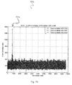
- FIG. 7 a is an example ghost cell simulation diagram 700 a illustrating the case of false detection of PSS 1 for an AWGN channel resulting in a “ghost” PSS 1 peak 701 a .
- the figure shows a PSS correlation snapshot for each of the 3 possible physical layer identities and for the AWGN channel scenario. The snapshot was stored in case of false detection of PSS 1 .
- a ghost PSS 1 peak 701 a can be seen for which no corresponding cell signal was configured in the simulation.
- CRS-IFFT processing according to the methods 300 , 500 as described above with respect to FIGS. 3 and 5 do not provide any significant peak results.
- FIG. 7 b is an example ghost cell simulation diagram 700 b illustrating the case of false detection of PSS 1 for an EPA 5 Hz channel resulting in a “ghost” PSS 1 peak 701 b .
- the figure shows a PSS correlation snapshot for each of the 3 possible physical layer identities and for the EPA 5 Hz channel scenario. The snapshot was stored in case of false detection of PSS 1 .
- a ghost PSS 1 peak 701 b can be seen for which no corresponding cell signal was configured in the simulation.
- CRS-IFFT processing according to the methods 300 , 500 as described above with respect to FIGS. 3 and 5 do not provide any significant peak results.
- FIG. 7 c is an example ghost cell simulation diagram 700 c illustrating the case of false detection of PSS 1 for an ETU 70 Hz channel resulting in a “ghost” PSS 1 peak 701 c .
- the figure shows a PSS correlation snapshot for each of the 3 possible physical layer identities and for the ETU 70 Hz channel scenario. The snapshot was stored in case of false detection of PSS 1 .
- a ghost PSS 1 peak 701 c can be seen for which no corresponding cell signal was configured in the simulation.
- CRS-IFFT processing according to the methods 300 , 500 as described above with respect to FIGS. 3 and 5 do not provide any significant peak results.
- FIG. 7 d is an example ghost cell simulation diagram 700 d illustrating the case of false detection of PSS 1 for an EVA 70 Hz channel resulting in a “ghost” PSS 1 peak 701 d .
- the figure shows a PSS correlation snapshot for each of the 3 possible physical layer identities and for the EVA 70 Hz channel scenario. The snapshot was stored in case of false detection of PSS 1 .
- a ghost PSS 1 peak 701 d can be seen for which no corresponding cell signal was configured in the simulation.
- CRS-IFFT processing according to the methods 300 , 500 as described above with respect to FIGS. 3 and 5 do not provide any significant peak results.
- FIG. 7 e is an example ghost cell simulation diagram 700 e illustrating the case of false detection of PSS 1 for an ETU 300 Hz channel resulting in a “ghost” PSS 1 peak 701 e .
- the figure shows a PSS correlation snapshot for each of the 3 possible physical layer identities and for the ETU 300 Hz channel scenario. The snapshot was stored in case of false detection of PSS 1 .
- a ghost PSS 1 peak 701 e can be seen for which no corresponding cell signal was configured in the simulation.
- CRS-IFFT processing according to the methods 300 , 500 as described above with respect to FIGS. 3 and 5 do not provide any significant peak results.
Landscapes
- Engineering & Computer Science (AREA)
- Signal Processing (AREA)
- Computer Networks & Wireless Communication (AREA)
- Computer Security & Cryptography (AREA)
- Mobile Radio Communication Systems (AREA)
Abstract
Description
AWGN Additive White Gaussian Noise,
EPA5: “Extended Pedestrian A” multi-path fading propagation conditions according to 3GPP technical specification 36.101 V11.3.0, using a Doppler frequency of 5 Hz,
EVA70: “Extended Vehicular A model” multi-path fading propagation conditions according to 3GPP technical Specification 36.101 V11.3.0, using a Doppler frequency of 70 Hz,
ETU70: “Extended Typical Urban model” multi-path fading propagation conditions according to 3GPP technical specification 36.101 V11.3.0, using a Doppler frequency of 70 Hz,
ETU300: “Extended Typical Urban model” multi-path fading propagation conditions according to 3GPP technical specification 36.101 V11.3.0, using a Doppler frequency of 300 Hz.
Adopted to LTE reference signals with DCRS=6 times ΔSC=15 kHz frequency spacing, the range of +/−Ω lies within the limit of:
MAX(SUM(ABS(IFFT(CRS_RX1))·^2+ABS(IFFT(CRSofdm_RX2))·^2) (3)
of all IFFT CRS symbol outputs, which means averaging after the absolute value operation ABS( ). MAX( ) describes a maximum value operation, SUM( ) describes a summation operation, ABS( ) describes an absolute value operation of each element of the vector IFFT(CRS_RX1), ·^2 denotes a square operation of each element of that squared vector, IFFT( ) describes an Inverse Fast Fourier Transform, CRS_RX1 describes a vector representing a set of cell-specific reference signals of
T 0 PSS=max(corrtime-domain(PSS)), (4)
where max( ) denotes maximum operation, corrtime-domain( ) denotes correlation function in time-domain and PSS denotes the primary synchronization signal.
T 0 CRSmax(IFFT(CRSfreq-domain)), (5)
where max( ) denotes maximum operation, IFFT( ) denotes inverse fast Fourier transform and CRSfreq-domain denotes CRS signal in frequency-domain.
Claims (18)
Priority Applications (1)
| Application Number | Priority Date | Filing Date | Title |
|---|---|---|---|
| US13/851,163 US9706480B2 (en) | 2013-03-27 | 2013-03-27 | Method for determining cell identification information |
Applications Claiming Priority (1)
| Application Number | Priority Date | Filing Date | Title |
|---|---|---|---|
| US13/851,163 US9706480B2 (en) | 2013-03-27 | 2013-03-27 | Method for determining cell identification information |
Publications (2)
| Publication Number | Publication Date |
|---|---|
| US20140293954A1 US20140293954A1 (en) | 2014-10-02 |
| US9706480B2 true US9706480B2 (en) | 2017-07-11 |
Family
ID=51620800
Family Applications (1)
| Application Number | Title | Priority Date | Filing Date |
|---|---|---|---|
| US13/851,163 Expired - Fee Related US9706480B2 (en) | 2013-03-27 | 2013-03-27 | Method for determining cell identification information |
Country Status (1)
| Country | Link |
|---|---|
| US (1) | US9706480B2 (en) |
Families Citing this family (8)
| Publication number | Priority date | Publication date | Assignee | Title |
|---|---|---|---|---|
| KR101791806B1 (en) * | 2013-12-12 | 2017-10-30 | 인텔 코포레이션 | User equipment and method for cell association and beamforming training with a mmwave capable small cell |
| CN106034345B (en) | 2015-04-17 | 2021-02-09 | 索尼公司 | Terminal side, base station side device, terminal device, base station, and wireless communication method |
| KR102412286B1 (en) * | 2015-09-02 | 2022-06-23 | 삼성전자 주식회사 | Method and apparatus for determining cell id in a wireless communication system |
| US10136405B2 (en) | 2015-09-18 | 2018-11-20 | Samsung Electronics Co., Ltd | System and method for RSRP measurement in an LTE UE receiver |
| DE102019129167B4 (en) * | 2018-11-28 | 2025-03-20 | Samsung Electronics Co., Ltd. | Operating method of a terminal in a wireless communication system and terminal for carrying out the method |
| KR102408559B1 (en) * | 2021-05-24 | 2022-06-14 | 주식회사 케이앤어스 | Method and Apparatus for Detecting Radio Signals that Transmit Illegally Collected Information through Pattern Analysis |
| US11705979B2 (en) * | 2021-09-24 | 2023-07-18 | Apple Inc. | Joint detection for primary synchronization signal (PSS) and other synchronization signal symbols in target cell search |
| CN120185757A (en) * | 2025-05-21 | 2025-06-20 | 杰创智能科技股份有限公司 | LTE cell search method and device |
Citations (12)
| Publication number | Priority date | Publication date | Assignee | Title |
|---|---|---|---|---|
| US20080267303A1 (en) * | 2007-04-30 | 2008-10-30 | Telefonaktiebolaget L M Ericsson (Publ) | Synchronization for Chirp Sequences |
| US20100182903A1 (en) * | 2009-01-16 | 2010-07-22 | Qualcomm Incorporated | Method and apparatus for transmitting overload indicator over the air |
| US20100246376A1 (en) * | 2009-03-25 | 2010-09-30 | Samsung Electronics Co., Ltd. | Cell-specific shifting of reference signals in multi-stream transmissions |
| US20110103350A1 (en) * | 2009-11-05 | 2011-05-05 | Bengt Lindoff | Handover Measurements in a Mobile Communication System |
| US20110143773A1 (en) * | 2009-12-14 | 2011-06-16 | Telefonaktiebolaget Lm Ericsson (Publ) | Defining adaptive detection thresholds |
| US20120163223A1 (en) * | 2010-10-29 | 2012-06-28 | Neocific, Inc. | Transmission of synchronization and control signals in a broadband wireless system |
| US20120163503A1 (en) * | 2009-06-19 | 2012-06-28 | St-Ericsson Sa | Process for Estimating the Channel from the PSS Signal in a LTE Communication Network, and Receiver for the Same |
| US20130070869A1 (en) * | 2011-09-20 | 2013-03-21 | Qualcomm Incorporated | Channel impulse response estimation for wireless receiver |
| US20140029483A1 (en) * | 2012-07-30 | 2014-01-30 | Qualcomm Incorporated | Method and apparatus for tdd virtual cell selection |
| US20140056165A1 (en) * | 2012-03-15 | 2014-02-27 | Telefonaktiebolaget L M Ericsson (Publ) | Verification in a Wireless Communication System |
| US20140112250A1 (en) * | 2011-04-05 | 2014-04-24 | Black Berry Limited | Method of interference cancellation and method of detection of erroneous neighbour cell measurements |
| US20150208328A1 (en) * | 2012-03-15 | 2015-07-23 | St-Ericsson Sa | Receiver and a Method Therein |
-
2013
- 2013-03-27 US US13/851,163 patent/US9706480B2/en not_active Expired - Fee Related
Patent Citations (12)
| Publication number | Priority date | Publication date | Assignee | Title |
|---|---|---|---|---|
| US20080267303A1 (en) * | 2007-04-30 | 2008-10-30 | Telefonaktiebolaget L M Ericsson (Publ) | Synchronization for Chirp Sequences |
| US20100182903A1 (en) * | 2009-01-16 | 2010-07-22 | Qualcomm Incorporated | Method and apparatus for transmitting overload indicator over the air |
| US20100246376A1 (en) * | 2009-03-25 | 2010-09-30 | Samsung Electronics Co., Ltd. | Cell-specific shifting of reference signals in multi-stream transmissions |
| US20120163503A1 (en) * | 2009-06-19 | 2012-06-28 | St-Ericsson Sa | Process for Estimating the Channel from the PSS Signal in a LTE Communication Network, and Receiver for the Same |
| US20110103350A1 (en) * | 2009-11-05 | 2011-05-05 | Bengt Lindoff | Handover Measurements in a Mobile Communication System |
| US20110143773A1 (en) * | 2009-12-14 | 2011-06-16 | Telefonaktiebolaget Lm Ericsson (Publ) | Defining adaptive detection thresholds |
| US20120163223A1 (en) * | 2010-10-29 | 2012-06-28 | Neocific, Inc. | Transmission of synchronization and control signals in a broadband wireless system |
| US20140112250A1 (en) * | 2011-04-05 | 2014-04-24 | Black Berry Limited | Method of interference cancellation and method of detection of erroneous neighbour cell measurements |
| US20130070869A1 (en) * | 2011-09-20 | 2013-03-21 | Qualcomm Incorporated | Channel impulse response estimation for wireless receiver |
| US20140056165A1 (en) * | 2012-03-15 | 2014-02-27 | Telefonaktiebolaget L M Ericsson (Publ) | Verification in a Wireless Communication System |
| US20150208328A1 (en) * | 2012-03-15 | 2015-07-23 | St-Ericsson Sa | Receiver and a Method Therein |
| US20140029483A1 (en) * | 2012-07-30 | 2014-01-30 | Qualcomm Incorporated | Method and apparatus for tdd virtual cell selection |
Non-Patent Citations (3)
| Title |
|---|
| "3rd Generation Partnership Project; Technical Specification Group Radio Access Network; Evolved Universal Terrestrial radio Access (E-UTRA); Physical Channels and Modulation (Release 11)"; 3GPP TS 36.211 v11.2.0 (Feb. 2013); p. 1-43. |
| Kaifeng Guo, et al.; "Differential Carrier Frequency Offset and Sampling Frequency Offset Estimation for 3GPP LTE"; 2011 IEEE, p. 1-5. |
| Wen Xu, et al.; "Robust Synchronization for 3GPP LTE System"; 2010 IEEE Globecom Proceedings, p. 1-5. |
Also Published As
| Publication number | Publication date |
|---|---|
| US20140293954A1 (en) | 2014-10-02 |
Similar Documents
| Publication | Publication Date | Title |
|---|---|---|
| US9706480B2 (en) | Method for determining cell identification information | |
| KR100827064B1 (en) | Synchronous signal transmission method and apparatus in an OFDM-based cellular wireless communication system | |
| CN101292461B (en) | Apparatus, method and computer program product providing initial cell acquisition and pilot sequence detection | |
| JP5788565B2 (en) | Base station and user equipment | |
| US8447005B2 (en) | Frequency synchronization methods and apparatus | |
| CN103782632B (en) | Small region search method in wireless communication system | |
| US10299147B2 (en) | Techniques for filtering candidate cells | |
| CN104113503A (en) | Methods and apparatus for LTE cell search with large frequency offset | |
| US9893925B1 (en) | Method and apparatus for joint time and frequency synchronization in wireless communication systems | |
| US10212679B1 (en) | Method and apparatus for delay spread estimation | |
| WO2008083910A1 (en) | Adaptive cell id detection in a cellular communications system | |
| US20130279448A1 (en) | Synchronization Transmissions in a Wireless Communication System | |
| Yoon et al. | Recovery of carrier frequency offset and set information for LTE device-to-device communications | |
| WO2008067721A1 (en) | Synchronization process method, base-station, user device and communication system | |
| EP2014116A2 (en) | Downlink synchronization channel and methods for cellular systems | |
| Andreescu et al. | Long term evolution primary synchronization algorithms | |
| Suyoto et al. | Improved timing estimation using iterative normalization technique for OFDM systems | |
| Lin et al. | Improved joint correlated detection in cell search and synchronization procedure in 3GPP LTE downlink system | |
| Milyutin et al. | Methods for improving the accuracy of frequency shift estimation in 5G NR | |
| Li et al. | Synchronization for b3g mimo ofdm in dl initial acquisition by cazac sequence | |
| Ali et al. | Cell search evaluation: A step towards the next generation LTE-MTC systems | |
| Ohiwa et al. | Effect of Power Boosting Primary Synchronization Signal on Physical Layer Cell ID Detection in NR Downlink | |
| Yang et al. | An efficient ToA estimation technique based on phase correction for 5G mMTC system | |
| Zhou et al. | Timing synchronization for interleaved OFDMA uplink system | |
| Lee et al. | Robust Timing Synchronization Algorithm for 5G New Radio |
Legal Events
| Date | Code | Title | Description |
|---|---|---|---|
| AS | Assignment |
Owner name: INTEL MOBILE COMMUNICATIONS GMBH, GERMANY Free format text: ASSIGNMENT OF ASSIGNORS INTEREST;ASSIGNORS:HORVAT, MICHAEL;PU, TIAN YAN;SIGNING DATES FROM 20130313 TO 20130326;REEL/FRAME:030391/0269 |
|
| AS | Assignment |
Owner name: INTEL DEUTSCHLAND GMBH, GERMANY Free format text: CHANGE OF NAME;ASSIGNOR:INTEL MOBILE COMMUNICATIONS GMBH;REEL/FRAME:037057/0061 Effective date: 20150507 |
|
| FEPP | Fee payment procedure |
Free format text: PAYOR NUMBER ASSIGNED (ORIGINAL EVENT CODE: ASPN); ENTITY STATUS OF PATENT OWNER: LARGE ENTITY |
|
| STCF | Information on status: patent grant |
Free format text: PATENTED CASE |
|
| FEPP | Fee payment procedure |
Free format text: MAINTENANCE FEE REMINDER MAILED (ORIGINAL EVENT CODE: REM.); ENTITY STATUS OF PATENT OWNER: LARGE ENTITY |
|
| LAPS | Lapse for failure to pay maintenance fees |
Free format text: PATENT EXPIRED FOR FAILURE TO PAY MAINTENANCE FEES (ORIGINAL EVENT CODE: EXP.); ENTITY STATUS OF PATENT OWNER: LARGE ENTITY |
|
| STCH | Information on status: patent discontinuation |
Free format text: PATENT EXPIRED DUE TO NONPAYMENT OF MAINTENANCE FEES UNDER 37 CFR 1.362 |
|
| FP | Lapsed due to failure to pay maintenance fee |
Effective date: 20210711 |
|
| AS | Assignment |
Owner name: INTEL CORPORATION, CALIFORNIA Free format text: ASSIGNMENT OF ASSIGNORS INTEREST;ASSIGNOR:INTEL DEUTSCHLAND GMBH;REEL/FRAME:061356/0001 Effective date: 20220708 |