US9703494B1 - Method and apparatus for protecting lower page data during programming in NAND flash - Google Patents
Method and apparatus for protecting lower page data during programming in NAND flash Download PDFInfo
- Publication number
- US9703494B1 US9703494B1 US15/276,080 US201615276080A US9703494B1 US 9703494 B1 US9703494 B1 US 9703494B1 US 201615276080 A US201615276080 A US 201615276080A US 9703494 B1 US9703494 B1 US 9703494B1
- Authority
- US
- United States
- Prior art keywords
- cells
- voltage
- program
- group
- storage device
- Prior art date
- Legal status (The legal status is an assumption and is not a legal conclusion. Google has not performed a legal analysis and makes no representation as to the accuracy of the status listed.)
- Active
Links
Images


Classifications
-
- G—PHYSICS
- G06—COMPUTING; CALCULATING OR COUNTING
- G06F—ELECTRIC DIGITAL DATA PROCESSING
- G06F3/00—Input arrangements for transferring data to be processed into a form capable of being handled by the computer; Output arrangements for transferring data from processing unit to output unit, e.g. interface arrangements
- G06F3/06—Digital input from, or digital output to, record carriers, e.g. RAID, emulated record carriers or networked record carriers
- G06F3/0601—Interfaces specially adapted for storage systems
- G06F3/0602—Interfaces specially adapted for storage systems specifically adapted to achieve a particular effect
- G06F3/061—Improving I/O performance
- G06F3/0611—Improving I/O performance in relation to response time
-
- G—PHYSICS
- G06—COMPUTING; CALCULATING OR COUNTING
- G06F—ELECTRIC DIGITAL DATA PROCESSING
- G06F11/00—Error detection; Error correction; Monitoring
- G06F11/07—Responding to the occurrence of a fault, e.g. fault tolerance
- G06F11/08—Error detection or correction by redundancy in data representation, e.g. by using checking codes
- G06F11/10—Adding special bits or symbols to the coded information, e.g. parity check, casting out 9's or 11's
- G06F11/1008—Adding special bits or symbols to the coded information, e.g. parity check, casting out 9's or 11's in individual solid state devices
- G06F11/1068—Adding special bits or symbols to the coded information, e.g. parity check, casting out 9's or 11's in individual solid state devices in sector programmable memories, e.g. flash disk
-
- G—PHYSICS
- G06—COMPUTING; CALCULATING OR COUNTING
- G06F—ELECTRIC DIGITAL DATA PROCESSING
- G06F3/00—Input arrangements for transferring data to be processed into a form capable of being handled by the computer; Output arrangements for transferring data from processing unit to output unit, e.g. interface arrangements
- G06F3/06—Digital input from, or digital output to, record carriers, e.g. RAID, emulated record carriers or networked record carriers
- G06F3/0601—Interfaces specially adapted for storage systems
- G06F3/0602—Interfaces specially adapted for storage systems specifically adapted to achieve a particular effect
- G06F3/0614—Improving the reliability of storage systems
- G06F3/0619—Improving the reliability of storage systems in relation to data integrity, e.g. data losses, bit errors
-
- G—PHYSICS
- G06—COMPUTING; CALCULATING OR COUNTING
- G06F—ELECTRIC DIGITAL DATA PROCESSING
- G06F3/00—Input arrangements for transferring data to be processed into a form capable of being handled by the computer; Output arrangements for transferring data from processing unit to output unit, e.g. interface arrangements
- G06F3/06—Digital input from, or digital output to, record carriers, e.g. RAID, emulated record carriers or networked record carriers
- G06F3/0601—Interfaces specially adapted for storage systems
- G06F3/0628—Interfaces specially adapted for storage systems making use of a particular technique
- G06F3/0638—Organizing or formatting or addressing of data
- G06F3/064—Management of blocks
-
- G—PHYSICS
- G06—COMPUTING; CALCULATING OR COUNTING
- G06F—ELECTRIC DIGITAL DATA PROCESSING
- G06F3/00—Input arrangements for transferring data to be processed into a form capable of being handled by the computer; Output arrangements for transferring data from processing unit to output unit, e.g. interface arrangements
- G06F3/06—Digital input from, or digital output to, record carriers, e.g. RAID, emulated record carriers or networked record carriers
- G06F3/0601—Interfaces specially adapted for storage systems
- G06F3/0668—Interfaces specially adapted for storage systems adopting a particular infrastructure
- G06F3/0671—In-line storage system
- G06F3/0673—Single storage device
- G06F3/0679—Non-volatile semiconductor memory device, e.g. flash memory, one time programmable memory [OTP]
-
- G—PHYSICS
- G11—INFORMATION STORAGE
- G11C—STATIC STORES
- G11C11/00—Digital stores characterised by the use of particular electric or magnetic storage elements; Storage elements therefor
- G11C11/56—Digital stores characterised by the use of particular electric or magnetic storage elements; Storage elements therefor using storage elements with more than two stable states represented by steps, e.g. of voltage, current, phase, frequency
- G11C11/5621—Digital stores characterised by the use of particular electric or magnetic storage elements; Storage elements therefor using storage elements with more than two stable states represented by steps, e.g. of voltage, current, phase, frequency using charge storage in a floating gate
- G11C11/5628—Programming or writing circuits; Data input circuits
-
- G—PHYSICS
- G11—INFORMATION STORAGE
- G11C—STATIC STORES
- G11C11/00—Digital stores characterised by the use of particular electric or magnetic storage elements; Storage elements therefor
- G11C11/56—Digital stores characterised by the use of particular electric or magnetic storage elements; Storage elements therefor using storage elements with more than two stable states represented by steps, e.g. of voltage, current, phase, frequency
- G11C11/5621—Digital stores characterised by the use of particular electric or magnetic storage elements; Storage elements therefor using storage elements with more than two stable states represented by steps, e.g. of voltage, current, phase, frequency using charge storage in a floating gate
- G11C11/5642—Sensing or reading circuits; Data output circuits
-
- G—PHYSICS
- G11—INFORMATION STORAGE
- G11C—STATIC STORES
- G11C16/00—Erasable programmable read-only memories
- G11C16/02—Erasable programmable read-only memories electrically programmable
- G11C16/04—Erasable programmable read-only memories electrically programmable using variable threshold transistors, e.g. FAMOS
- G11C16/0483—Erasable programmable read-only memories electrically programmable using variable threshold transistors, e.g. FAMOS comprising cells having several storage transistors connected in series
-
- G—PHYSICS
- G11—INFORMATION STORAGE
- G11C—STATIC STORES
- G11C16/00—Erasable programmable read-only memories
- G11C16/02—Erasable programmable read-only memories electrically programmable
- G11C16/06—Auxiliary circuits, e.g. for writing into memory
- G11C16/34—Determination of programming status, e.g. threshold voltage, overprogramming or underprogramming, retention
- G11C16/3436—Arrangements for verifying correct programming or erasure
- G11C16/3454—Arrangements for verifying correct programming or for detecting overprogrammed cells
- G11C16/3459—Circuits or methods to verify correct programming of nonvolatile memory cells
-
- G—PHYSICS
- G11—INFORMATION STORAGE
- G11C—STATIC STORES
- G11C29/00—Checking stores for correct operation ; Subsequent repair; Testing stores during standby or offline operation
- G11C29/52—Protection of memory contents; Detection of errors in memory contents
-
- G—PHYSICS
- G11—INFORMATION STORAGE
- G11C—STATIC STORES
- G11C2211/00—Indexing scheme relating to digital stores characterized by the use of particular electric or magnetic storage elements; Storage elements therefor
- G11C2211/56—Indexing scheme relating to G11C11/56 and sub-groups for features not covered by these groups
- G11C2211/562—Multilevel memory programming aspects
- G11C2211/5621—Multilevel programming verification
-
- G—PHYSICS
- G11—INFORMATION STORAGE
- G11C—STATIC STORES
- G11C2211/00—Indexing scheme relating to digital stores characterized by the use of particular electric or magnetic storage elements; Storage elements therefor
- G11C2211/56—Indexing scheme relating to G11C11/56 and sub-groups for features not covered by these groups
- G11C2211/564—Miscellaneous aspects
- G11C2211/5648—Multilevel memory programming, reading or erasing operations wherein the order or sequence of the operations is relevant
Definitions
- the present disclosure relates in general to the field of computer development, and more specifically, to NAND flash memory.
- a computer system may include one or more central processing units (CPUs) coupled to one or more storage devices.
- CPU may include a processor to execute an operating system and other software applications that utilize the storage devices coupled to the CPU.
- the software applications may write data to the storage devices.
- the data may be stored by the storage devices in a plurality of memory cells (e.g., NAND flash memory cells) of the storage devices.
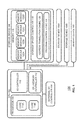
- FIG. 1 illustrates a block diagram of components of a computer system in accordance with certain embodiments.
- FIG. 2 illustrates an example diagram of a portion of a NAND flash memory array in accordance with certain embodiments.
- FIG. 3 illustrates example encoding schemes for NAND flash memory cells in accordance with certain embodiments.
- FIG. 4 illustrates an example programming sequence for tri-level cell (TLC) NAND flash memory cells in accordance with certain embodiments.
- FIG. 5 illustrates an example flow for programming NAND flash memory cells in accordance with certain embodiments.
- FIG. 1 depicts particular computer systems, the concepts of various embodiments are applicable to any suitable integrated circuits and other logic devices.
- devices in which teachings of the present disclosure may be used include desktop computer systems, server computer systems, storage systems, handheld devices, tablets, other thin notebooks, systems on a chip (SOC) devices, and embedded applications.
- Some examples of handheld devices include cellular phones, digital cameras, media players, personal digital assistants (PDAs), and handheld PCs.
- Embedded applications may include a microcontroller, a digital signal processor (DSP), a system on a chip, network computers (NetPC), set-top boxes, network hubs, wide area network (WAN) switches, or any other system that can perform the functions and operations taught below.
- DSP digital signal processor
- NetPC network computers
- Set-top boxes network hubs
- WAN wide area network
- Various embodiments of the present disclosure may be used in any suitable computing environment, such as a personal computing device, a server, a mainframe, a cloud computing service provider infrastructure, a datacenter, a communications service provider infrastructure (e.g., one or more portions of an Evolved Packet Core), or other environment comprising a group of computing devices.
- a personal computing device such as a server, a mainframe, a cloud computing service provider infrastructure, a datacenter, a communications service provider infrastructure (e.g., one or more portions of an Evolved Packet Core), or other environment comprising a group of computing devices.
- a communications service provider infrastructure e.g., one or more portions of an Evolved Packet Core
- FIG. 1 illustrates a block diagram of components of a computer system 100 in accordance with certain embodiments.
- System 100 includes a central processing unit (CPU) 102 coupled to an external input/output (I/O) controller 104 , a plurality of storage devices 106 , 106 A, and 106 B ( 106 A and 106 B may perform in similar manners to storage device 106 and/or may have any suitable characteristics of storage device 106 ), and memory device 107 .
- data may be transferred between storage devices 106 or memory device 107 and the CPU 102 .
- particular data operations involving a storage device 106 or memory device 107 may be managed by an operating system or other software application executed by processor 108 .
- a storage device 106 comprises NAND flash memory.
- storage device 106 may be a solid state drive; a memory card; a Universal Serial Bus (USB) flash drive; or memory integrated within a device such as a smartphone, camera, media player, or other computing device.
- USB Universal Serial Bus
- storage devices with NAND flash memory are classified by the number of bits stored by each cell of the memory.
- a single-level cell (SLC) memory has cells that each store one bit of data
- a multi-level cell (MLC) memory has cells that each store two bits of data
- a tri-level cell (TLC) memory has cells that each store three bits of data
- a quad-level cell (QLC) memory has cells that each store four bits of data, though some memories may utilize multiple encoding schemes (e.g., MLC and TLC) on the same array.
- MLC multi-level cell
- TLC tri-level cell
- QLC quad-level cell
- a program (i.e., write) sequence for a NAND flash memory generally includes numerous program loops to program cells of memory.
- a program loop generally includes application of one or more program voltages (e.g., pulses) followed by one or more program verify voltages (e.g., pulses).
- the program voltage(s) may be stepped higher in every subsequent program loop to allow or assist slower-to-program cells to reach their respective target threshold voltage levels. Cells reaching their respective target levels (as determined via the program verify voltages) are inhibited in all subsequent program pulses such that they may maintain their programmed threshold voltages.
- Program loops may continue to be performed until all (or most) cells being programmed reach their target threshold voltage. Cells that do not reach their target threshold voltage may be fixed via an error correction code (ECC) capability of the memory.
- ECC error correction code
- multi-level cell programming in which the cells of a NAND flash memory each store two or more bits
- the first pass programs one or more lower page(s)/bit(s) in the group of cells and one or more subsequent passes program the higher pages(s)/bit(s) in the same group of cells.
- a page is readable if there is sufficient margin between adjacent levels of threshold voltage distributions corresponding to bit values of the page (such margins are described in more detail in connection with FIGS. 3 and 4 ).
- a single page may be read from cells storing multiple pages after complete programming of the first pass (which stores the lower bit(s)/page(s)) as well as one or more subsequent passes (which store the higher bit(s)/page(s)).
- the program sequence is interrupted during the one or more subsequent passes (e.g., in the event of a power loss)
- the lower page(s) may become unreadable due to the programming of the higher pages causing particular cells (e.g., cells that transition to higher threshold voltages more quickly than others) to cross over a read voltage threshold used to distinguish between values of the lower page(s).
- there is a possibility of corruption of the lower page(s) data if the program operation of the higher pages(s) is started but not completed.
- Various embodiments of the present disclosure provide the ability to ensure the readability of the lower page(s) of data throughout the programming sequence, even if the sequence is aborted after the lower page(s) are programmed and before the programming of the upper page(s) is complete.
- Particular embodiments include application of multi-pulse programming (MPP) techniques that can ensure the maintenance of suitable margins between adjacent levels of threshold voltage distributions throughout the course of programming.
- MPP multi-pulse programming
- Particular embodiments may reduce the programming time relative to other solutions that try to achieve lower page(s) immunity to power loss during upper page(s) programming by placing the levels in the lower page(s) further away from each other (i.e., placing first pass threshold voltage distributions more tightly which generally results in increased programming time due to the finer program voltages that are used).
- Various embodiments of the present disclosure may provide technical advantages, such as providing readability of written data despite program interruption, reducing programming time, and other technical advantages.
- CPU 102 comprises a processor 108 , such as a microprocessor, an embedded processor, a digital signal processor (DSP), a network processor, a handheld processor, an application processor, a co-processor, a system on a chip (SOC), or other device to execute code (i.e., software instructions).
- processor 108 in the depicted embodiment, includes two processing elements (cores 114 A and 114 B in the depicted embodiment), which may include asymmetric processing elements or symmetric processing elements. However, a processor may include any number of processing elements that may be symmetric or asymmetric.
- a processing element refers to hardware or logic to support a software thread.
- hardware processing elements include: a thread unit, a thread slot, a thread, a process unit, a context, a context unit, a logical processor, a hardware thread, a core, and/or any other element, which is capable of holding a state for a processor, such as an execution state or architectural state.
- a processing element in one embodiment, refers to any hardware capable of being independently associated with code, such as a software thread, operating system, application, or other code.
- a physical processor or processor socket typically refers to an integrated circuit, which potentially includes any number of other processing elements, such as cores or hardware threads.
- a core 114 may refer to logic located on an integrated circuit capable of maintaining an independent architectural state, wherein each independently maintained architectural state is associated with at least some dedicated execution resources.
- a hardware thread may refer to any logic located on an integrated circuit capable of maintaining an independent architectural state, wherein the independently maintained architectural states share access to execution resources. As can be seen, when certain resources are shared and others are dedicated to an architectural state, the line between the nomenclature of a hardware thread and core overlaps. Yet often, a core and a hardware thread are viewed by an operating system as individual logical processors, where the operating system is able to individually schedule operations on each logical processor.
- the processing elements may also include one or more arithmetic logic units (ALUs), floating point units (FPUs), caches, instruction pipelines, interrupt handling hardware, registers, or other hardware to facilitate the operations of the processing elements.
- ALUs arithmetic logic units
- FPUs floating point units
- caches instruction pipelines
- interrupt handling hardware registers, or other hardware to facilitate the operations of the processing elements.
- I/O controller 110 is an integrated I/O controller that includes logic for communicating data between CPU 102 and I/O devices, which may refer to any suitable devices capable of transferring data to and/or receiving data from an electronic system, such as CPU 102 .
- an I/O device may comprise an audio/video (A/V) device controller such as a graphics accelerator or audio controller; a data storage device controller, such as a flash memory device, magnetic storage disk, or optical storage disk controller; a wireless transceiver; a network processor; a network interface controller; or a controller for another input devices such as a monitor, printer, mouse, keyboard, or scanner; or other suitable device.
- A/V audio/video
- an I/O device may comprise a storage device 106 coupled to the CPU 102 through I/O controller 110 .
- An I/O device may communicate with the I/O controller 110 of the CPU 102 using any suitable signaling protocol, such as peripheral component interconnect (PCI), PCI Express (PCIe), Universal Serial Bus (USB), Serial Attached SCSI (SAS), Serial ATA (SATA), Fibre Channel (FC), IEEE 802.3, IEEE 802.11, or other current or future signaling protocol.
- PCI peripheral component interconnect
- PCIe PCI Express
- USB Universal Serial Bus
- SAS Serial Attached SCSI
- SAS Serial ATA
- FC Fibre Channel
- IEEE 802.3 IEEE 802.11, or other current or future signaling protocol.
- I/O controller 110 and the underlying I/O device may communicate data and commands in accordance with a logical device interface specification such as Non-Volatile Memory Express (NVMe) (e.g., as described by one or more of the specifications available at www.nvmexpress.org/specifications/) or Advanced Host Controller Interface (AHCI) (e.g., as described by one or more AHCI specifications such as Serial ATA AHCI: Specification, Rev. 1.3.1 available at http://www.intel.com/content/www/us/en/io/serial-ata/serial-ata-ahci-spec-rev1-3-1.html).
- I/O devices coupled to the I/O controller may be located off-chip (i.e., not on the same chip as CPU 102 ) or may be integrated on the same chip as the CPU 102 .
- CPU memory controller 112 is an integrated memory controller that includes logic to control the flow of data going to and from one or more memory devices 107 .
- CPU memory controller 112 may include logic operable to read from a memory device 107 , write to a memory device 107 , or to request other operations from a memory device 107 .
- CPU memory controller 112 may receive write requests from cores 114 and/or I/O controller 110 and may provide data specified in these requests to a memory device 107 for storage therein.
- CPU memory controller 112 may also read data from a memory device 107 and provide the read data to I/O controller 110 or a core 114 .
- CPU memory controller 112 may issue commands including one or more addresses of the memory device 107 in order to read data from or write data to memory (or to perform other operations).
- CPU memory controller 112 may be implemented on the same chip as CPU 102 , whereas in other embodiments, CPU memory controller 112 may be implemented on a different chip than that of CPU 102 .
- I/O controller 110 may perform similar operations with respect to one or more storage devices 106 .
- the CPU 102 may also be coupled to one or more other I/O devices through external I/O controller 104 .
- external I/O controller 104 may couple a storage device 106 to the CPU 102 .
- External I/O controller 104 may include logic to manage the flow of data between one or more CPUs 102 and I/O devices.
- external I/O controller 104 is located on a motherboard along with the CPU 102 .
- the external I/O controller 104 may exchange information with components of CPU 102 using point-to-point or other interfaces.
- a memory device 107 may store any suitable data, such as data used by processor 108 to provide the functionality of computer system 100 .
- data associated with programs that are executed or files accessed by cores 110 may be stored in memory device 107 .
- a memory device 107 may include a system memory that stores data and/or sequences of instructions that are used or executed by the cores 114 .
- a memory device 107 may store persistent data (e.g., a user's files or instruction sequences) that remains stored even after power to the memory device 107 is removed.
- a memory device 107 may be dedicated to a particular CPU 102 or shared with other devices (e.g., one or more other processors or other device) of computer system 100 .
- a memory device 107 may include a memory comprising any number of memory modules, a memory device controller, and other supporting logic (not shown).
- a memory module may include non-volatile memory and/or volatile memory.
- Non-volatile memory is a storage medium that does not require power to maintain the state of data stored by the medium.
- Nonlimiting examples of nonvolatile memory may include any or a combination of: solid state memory (such as planar or 3D NAND flash memory or NOR flash memory), 3D crosspoint memory, memory devices that use chalcogenide phase change material (e.g., chalcogenide glass), byte addressable nonvolatile memory devices, ferroelectric memory, silicon-oxide-nitride-oxide-silicon (SONOS) memory, polymer memory (e.g., ferroelectric polymer memory), ferroelectric transistor random access memory (Fe-TRAM) ovonic memory, nanowire memory, electrically erasable programmable read-only memory (EEPROM), other various types of non-volatile random access memories (RAMs), and magnetic storage memory.
- solid state memory such as planar or 3D NAND flash memory or NOR flash memory
- 3D crosspoint memory such as planar or 3D NAND flash memory or NOR flash memory
- memory devices that use chalcogenide phase change material e.g., chalcogenide
- 3D crosspoint memory may comprise a transistor-less stackable cross point architecture in which memory cells sit at the intersection of words lines and bit lines and are individually addressable and in which bit storage is based on a change in bulk resistance.
- Volatile memory is a storage medium that requires power to maintain the state of data stored by the medium. Examples of volatile memory may include various types of random access memory (RAM), such as dynamic random access memory (DRAM) or static random access memory (SRAM).
- DRAM dynamic random access memory
- SRAM static random access memory
- DRAM dynamic random access memory
- SDRAM synchronous dynamic random access memory
- any portion of memory 107 that is volatile memory can comply with JEDEC standards including but not limited to Double Data Rate (DDR) standards, e.g., DDR3, 4, and 5, or Low Power DDR4 (LPDDR4) as well as emerging standards.
- DDR Double Data Rate
- LPDDR4 Low Power DDR4
- a storage device 106 may store any suitable data, such as data used by processor 108 to provide functionality of computer system 100 .
- data associated with programs that are executed or files accessed by cores 114 may be stored in storage device 106 .
- a storage device 106 may include a system memory that stores data and/or sequences of instructions that are used or executed by the cores 114 .
- a storage device 106 may store persistent data (e.g., a user's files or software application code) that remains stored even after power to the storage device 106 is removed.
- a storage device 106 may be dedicated to CPU 102 or shared with other devices (e.g., another CPU or other device) of computer system 100 .
- storage device 106 includes a storage device controller 118 and a memory 116 comprising a plurality of memory modules 122 A-D, however, a storage device may include any suitable number of memory modules 122 .
- a memory module 122 includes a plurality of memory cells that are each operable to store one or more bits.
- the cells of a memory module 122 may be arranged in any suitable fashion, such as in rows (e.g., wordlines) and columns (e.g., bitlines), three dimensional structures, or other manner.
- the cells may be logically grouped into banks, blocks, subblocks, wordlines, pages, frames, bytes, or other suitable groups.
- a memory module 122 comprises one or more NAND flash memory arrays. NAND flash memory arrays are described in more detail in connection with FIG. 2 .
- a memory module 122 may include non-volatile memory, such as planar or 3D NAND flash memory.
- Non-volatile memory is a storage medium that does not require power to maintain the state of data stored by the medium.
- a memory module 122 with non-volatile memory may comply with one or more standards for non-volatile memory promulgated by the Joint Electron Device Engineering Council (JEDEC), such as JESD218, JESD219, JESD220-1, JESD220C, JESD223C, JESD223-1, or other suitable standard (the JEDEC standards cited herein are available at www.jedec.org).
- JEDEC Joint Electron Device Engineering Council
- the storage device comprises NAND flash memory that complies with one or more portions of a standard promulgated by JEDEC for SDRAM memory, such as JESD79F for Double Data Rate (DDR) SDRAM, JESD79-2F for DDR2 SDRAM, JESD79-3F for DDR3 SDRAM, or JESD79-4A for DDR4 SDRAM (these standards are available at www.jedec.org).
- JESD79F Double Data Rate
- JESD79-2F for DDR2 SDRAM
- JESD79-3F for DDR3 SDRAM
- JESD79-4A for DDR4 SDRAM
- a storage device 106 comprising NAND flash memory may receive a command that has a format compliant with a DDR-based standard and may translate the command into one or more commands that are compatible with NAND flash memory of the storage device 106 .
- the storage device 106 may format results from operations performed on the NAND flash memory into a format that is compliant with a DDR-based standard before transmitting the results to the CPU 102 .
- Storage devices 106 may comprise any suitable type of memory and are not limited to a particular speed, technology, or form factor of memory in various embodiments.
- a storage device 106 could be a disk drive (such as a solid state drive), a flash drive, memory integrated with a computing device (e.g., memory integrated on a circuit board of the computing device), a memory module (e.g., a dual in-line memory module) that may be inserted in a memory socket, or other type of storage device.
- computer system 100 may include multiple different types of storage devices 106 .
- Storage devices 106 may include any suitable interface to communicate with CPU memory controller 112 or I/O controller 110 using any suitable communication protocol such as a DDR-based protocol, PCI, PCIe, USB, SAS, SATA, FC, System Management Bus (SMBus), or other suitable protocol.
- Storage devices 106 may also include a communication interface to communicate with CPU memory controller 112 or I/O controller 110 in accordance with any suitable logical device interface specification such as NVMe, AHCI, or other suitable specification.
- storage device 106 may comprise multiple communication interfaces that each communicate using a separate protocol with CPU memory controller 112 and/or I/O controller 110 .
- Storage device controller 118 may include logic to receive requests from CPU 102 (e.g., via CPU memory controller 112 or I/O controller 110 ), cause the requests to be carried out with respect to memory 116 , and provide data associated with the requests to CPU 102 (e.g., via CPU memory controller 112 or I/O controller 110 ). Controller 118 may also be operable to detect and/or correct errors encountered during memory operation. In an embodiment, controller 118 also tracks the number of times particular cells (or logical groupings of cells) have been written to in order to perform wear leveling and/or to detect when cells are nearing an estimated number of times they may be reliably written to.
- the storage device controller 118 may evenly spread out write operations among blocks of the memory 116 such that particular blocks are not written to more than other blocks. In various embodiments, controller 118 may also monitor various characteristics of the storage device 106 such as the temperature or voltage and report associated statistics to the CPU 102 .
- Storage device controller 118 can be implemented on the same chip, board, or device as memory 116 or on a different chip, board, or device. For example, in some environments, storage device controller 118 may be a centralized storage controller that manages memory operations for multiple different memories 116 (which could each be of the same type or could be of different types) of computer system 100 (and thus could provide storage device controller functionality described herein to any of the memories to which it is coupled).
- the storage device 106 also includes an address translation engine 120 .
- the address translation engine 120 is shown as part of the storage device controller 118 , although in various embodiments, the address translation engine 120 may be separate from the storage device controller 118 and communicably coupled to the storage device controller 118 . In various embodiments, the address translation engine 120 may be integrated on the same chip as the storage device controller 118 or on a different chip.
- address translation engine 120 may include logic to store and update a mapping between a logical address space (e.g., an address space visible to a computing host coupled to the storage device 106 ) and the physical address space of the memory 116 (which may or may not be exposed to the computing host).
- the logical address space may expose a plurality of logical groups of data which are physically stored on corresponding physical groups of memory addressable through the physical address space of the storage device 106 .
- a physical address of the physical address space may comprise any suitable information identifying a physical memory location (e.g., a location within memory 116 ) of the storage device 106 , such as an identifier of the memory module 122 on which the physical memory location is located, one or more pages of the physical memory location, one or more subblocks of the physical memory location, one or more wordlines of the physical memory location, one or more bitlines of the physical memory location, or other suitable identifiers or encodings thereof.
- a physical memory location e.g., a location within memory 116
- the storage device 106 such as an identifier of the memory module 122 on which the physical memory location is located, one or more pages of the physical memory location, one or more subblocks of the physical memory location, one or more wordlines of the physical memory location, one or more bitlines of the physical memory location, or other suitable identifiers or encodings thereof.
- the address translation engine 120 or other portion of storage device 106 may include any suitable memory type for storing logical to physical mapping structures and other information and any suitable logic for changing values stored in the logical to physical mapping structures and other information (e.g., in response to a request from the storage device controller 118 ) and reading values from the logical to physical mapping structures and other information (e.g., to provide the values to the storage device controller 118 for use in memory operations).
- Storage media for the logical to physical mapping structures and other information may be included within the address translation engine 120 and/or storage device controller 118 or may be communicably coupled to the address translation engine and/or storage device controller. In various embodiments, storage media for the logical to physical mapping structures and other information may be integrated on the same chip as the storage device controller 118 and/or address translation engine 120 or may be implemented on a separate chip.
- the address translation engine 120 and/or storage device controller 118 may provide wear leveling through management of the address mappings of the logical to physical mapping structures and other information. In particular embodiments, the address translation engine 120 and/or storage device controller 118 may also prevent the use of bad memory cells (or logical grouping of cells) by not allowing physical addresses for the bad cells (or logical grouping of cells) to be mapped to the logical address space.
- the storage device 106 also includes program control logic 124 which is operable to control the programming sequence performed when data is written to memory 116 .
- program control logic 124 may provide the various voltages that applied to the memory cells during the programming and/or reading of one or more pages of data, perform error correction, and perform other suitable functions.
- the program control logic 124 may be integrated on the same chip as the storage device controller 118 or on a different chip. In the depicted embodiment, the program control logic 124 is shown as part of the storage device controller 118 , although in various embodiments, all or a portion of the program control logic 124 may be separate from the storage device controller 118 and communicably coupled to the storage device controller 118 . For example, all or a portion of the program control logic 124 may be located on the same chip as memory 116 and/or memory modules 122 .
- all or some of the elements of system 100 are resident on (or coupled to) the same circuit board (e.g., a motherboard).
- any suitable partitioning between the elements may exist.
- the elements depicted in CPU 102 may be located on a single die or package (i.e., on-chip) or any of the elements of CPU 102 may be located off-chip.
- the elements depicted in storage device 106 may be located on a single chip or on multiple chips.
- a storage device 106 and a computing host e.g., CPU 102
- the storage device 106 and the computing host may be located on different circuit boards or devices.
- a bus may couple any of the components together.
- a bus may include any known interconnect, such as a multi-drop bus, a mesh interconnect, a ring interconnect, a point-to-point interconnect, a serial interconnect, a parallel bus, a coherent (e.g. cache coherent) bus, a layered protocol architecture, a differential bus, and a Gunning transceiver logic (GTL) bus.
- GTL Gunning transceiver logic
- an integrated I/O subsystem includes point-to-point multiplexing logic between various components of system 100 , such as cores 114 , one or more CPU memory controllers 112 , I/O controller 110 , integrated I/O devices, direct memory access (DMA) logic (not shown), etc.
- components of computer system 100 may be coupled together through one or more networks comprising any number of intervening network nodes, such as routers, switches, or other computing devices.
- a computing host e.g., CPU 102
- the storage device 106 may be communicably coupled through a network.
- system 100 may use a battery and/or power supply outlet connector and associated system to receive power, a display to output data provided by CPU 102 , or a network interface allowing the CPU 102 to communicate over a network.
- the battery, power supply outlet connector, display, and/or network interface may be communicatively coupled to CPU 102 .
- Other sources of power can be used such as renewable energy (e.g., solar power or motion based power).
- FIG. 2 illustrates an example diagram of a portion of a NAND flash memory array 200 in accordance with certain embodiments.
- NAND flash memory array 200 may comprise a plurality of non-volatile memory cells 202 arranged in columns such as series strings 204 .
- a memory cell 202 may comprise a transistor with a floating gate that stores charge indicative of one or more bit values stored by the memory cell 202 .
- the drains of the cells 202 are each (with the exception of the top cell) coupled to a source of another cell 202 .
- the array 200 also includes wordlines 206 .
- a wordline 206 may span across multiple series strings 204 (e.g., a wordline may be coupled to one memory cell of each series string 204 ) and are connected to the control gates of each memory cell 202 of a row of the array 200 and used to bias the control gates of the memory cells 202 in the row.
- the bitlines 208 are each coupled to a series string 204 by a drain select gate 214 and sensing circuitry 220 that detects the state of each cell by sensing voltage or current on a particular bitline 208 .
- Each series string 204 of memory cells is coupled to a source line 210 by a source select gate 212 and to an individual bitline 208 by a drain select gate 214 .
- the source select gates 212 are controlled by a source select gate control line 216 and the drain select gates 214 are controlled by a drain select gate control line 218 .
- each memory cell 202 can be programmed according to an SLC, MLC, TLC, a QLC, or other encoding scheme.
- Each cell's threshold voltage (Vt) is indicative of the data that is stored in the cell.
- FIG. 3 illustrates example encodings of bits within NAND flash memory cells 202 in accordance with certain embodiments.
- each elliptical region represents a range of threshold voltages that correspond to the value encoded within the cell. For example, in the SLC encoding scheme, lower threshold voltages correspond to the bit value 1 and higher threshold voltages correspond to the bit value 0.
- the lowest range of threshold voltages corresponds to “11”, the next highest range of threshold voltages corresponds to “01”, the next highest range of threshold voltages corresponds to “00”, and the highest range of threshold voltages correspond to “10.”
- various ranges of threshold voltages correspond to various values of the bits encoded within each cell.
- a program level may refer to one of the depicted regions.
- a program level may correspond to one of the bit encodings used in the encoding scheme.
- the next lowest region e.g., “01” of the MLC scheme or “011” of the TLC scheme
- the next region e.g., “00” of the MLC scheme or “001” of the TLC scheme
- the second program level e.g., “00” of the MLC scheme or “001” of the TLC scheme
- the MLC scheme has three program levels
- the TLC scheme has seven program levels
- the QLC scheme has fifteen program levels.
- data e.g., one or more pages
- a plurality of the cells may be programmed to a first program level
- a plurality of the cells may be programmed to a second program level, and so on.
- the various R voltage values depicted in FIG. 3 represent read voltages that may be applied to a wordline when the values of the cells are being read.
- sense circuitry 220 may determine whether the threshold value of a cell is greater than or less than the read voltage based on a voltage or current sensed by the sense circuitry 220 via the bitline of the cell.
- a QLC encoding scheme may utilize a similar scheme where fifteen read voltages may be used to resolve the values of four bits within each cell, where R1 ⁇ R2 ⁇ R3 ⁇ . . . ⁇ R15.
- the various program verify voltages (PV1-PV3 in the MLC encoding scheme and PV1-PV7 in the TLC encoding scheme) depicted represent program verify voltages that may be applied to a cell during programming of the cell to determine whether the threshold voltage of the cell has reached its desired level. For example, in the MLC encoding scheme, if the cell is to be programmed to “01” (i.e., program level 1), then PV1 may be applied to the cell during a verify procedure and if sensing circuitry 220 determines that the threshold voltage of the cell is greater than PV1, then the cell is considered to have passed programming.
- the cell is considered to not have passed programming and the storage device 106 may attempt to raise the threshold voltage of the cell or may allow the cell to fail and may later attempt error correction on the cell.
- the cell is to be programmed to “00” (i.e., program level 2)
- PV2 may be applied to the cell during a verify procedure and if sensing circuitry 220 determines that the threshold voltage of the cell is greater than PV2, then the cell is considered to have passed programming.
- the cell is to be programmed to “10” (i.e., program level 3)
- PV3 may be applied to the cell during a verify procedure. Any suitable program verify voltages may be used for any of the encoding schemes.
- the program verify voltage may be set to a value that is at or near the beginning of the corresponding threshold voltage range.
- the figure depicts a margin in between R1 and PV1, between R2 and PV2, and so on.
- cells may be programmed a page at a time, where a page is stored in a group of cells that are coupled to the same wordline.
- the group of cells may be identified by a particular wordline and a particular subblock.
- the group of cells may represent all of the cells of the wordline.
- the group of cells may store one page of data (if the cells are encoded according to an SLC scheme) or multiple pages of data (if the cells are encoded according to an MLC, TLC, QLC, or other multi-level encoding scheme).
- a cell that is encoded to store multiple bits may form a part of multiple different pages, with each bit of the cell corresponding to a distinct page.
- each bit of the cell may correspond to a distinct page.
- one bit may correspond to an Upper Page (UP) and the other bit may correspond to a Lower Page (LP).
- UP Upper Page
- LP Lower Page
- XP Extra Page
- each page (e.g., LP, UP, XP, or TP) may comprise an aggregation of corresponding bits stored by a plurality of different cells of a wordline. For example, referring to the encoding shown in FIG.
- all of the rightmost bits of a plurality of cells encoded using a TLC scheme may form an LP
- all of the middle bits of the plurality of cells may form a UP
- all of the leftmost bits of the plurality of cells may form an XP.
- a programming sequence for a group of cells may comprise programming of all of the intended pages into the group of cells.
- a programming sequence may include one or more programming passes.
- a programming pass (which may comprise one or more programming loops) may encode one or more pages.
- a programming pass may comprise the application of one or more effective program voltages to cells to be programmed followed by the application of one or more verify voltages to these cells in order to determine which cells have finished programming (subsequent programming passes generally will not apply an effective program voltage and/or a verify voltage to the cells that have finished programming).
- one or more loops of a programming pass may comprise the application of one or more effective program voltages without the application of one or more verify voltages.
- the application of an effective program voltage to a cell may include changing the voltage difference between a control gate and a channel of the cell in order to change the threshold voltage of the cell.
- the voltage of a wordline (coupled to the control gate of the target cell) and/or a channel of the cell may be set in order to effectuate application of an effective program voltage.
- program voltage is commonly used to refer to a voltage applied to a wordline
- effective program voltage will be used herein to refer to the voltage difference between a control gate and channel of a cell (which in instances where the channel is held at 0 V will be synonymous with program voltage).
- a programming pass may program one or more pages.
- both pages (the LP and the UP) may be programmed during a single programming pass by setting the voltage levels of the cells to the desired program level (e.g., within one of the four voltage ranges depicted for the MLC scheme in FIG. 3 ).
- an LP could be programmed in a first pass and a UP could be programmed in a second pass.
- first bits of the cells (where the first bits of the cells collectively form the LP) may be programmed to a binary state based on the desired value of each bit. For example, referring to the MLC scheme depicted in FIG.
- the Vt of the cell may be programmed to a value that is slightly greater than PV2 in the first programming pass (or at least a portion of the way to PV2 so as to be distinguished from cells that are left in a low voltage erased state). If a particular rightmost bit is to be stored as a ‘1’ value, it may be left at a low voltage level.
- second bits of the same cells are programmed, resulting in the Vt of the cells being changed to their desired Vt (e.g., within one of the four voltage ranges depicted for the MLC scheme in FIG. 3 ), thus storing values for the UP and the LP.
- all pages may be programmed during a single programming pass by setting the voltage levels of the cells to the desired program level, or one or more of the pages may be programmed during a first pass and the remaining pages programmed during a second pass (or the remaining pages may be programmed using multiple additional passes).
- a first pass may encode an LP and a second pass may encode the UP and the XP.
- a first pass may encode an LP and a UP and a second pass may encode the XP and the TP or a first pass may encode the LP and a second pass may encode the UP, XP, and TP.
- lower page(s) may be used to refer to one or more pages that are programmed in a first programming pass and upper page(s) may be used to refer to one or more pages that are programmed in one or more subsequent programming passes. These designations may be distinguished from the Lower Page and Upper Page previously described (in general a Lower Page will be a lower page as used herein when multiple programming passes are used while an Upper Page may be a lower page or an upper page depending on whether it is programmed in the first programming pass or in a subsequent programming pass).
- a lower page e.g., the LP
- an upper page e.g., the UP
- a lower page e.g., the LP
- upper pages e.g., the UP and the XP
- second programming pass e.g., the UP and the XP
- a lower page e.g., the LP
- upper pages e.g., the UP, XP, and TP
- lower pages e.g., the LP and the UP
- upper pages e.g., the XP and the TP
- Any other suitable permutations of pages programmed in programming passes is contemplated in this disclosure including multiple passes being used to program the upper pages.
- one or more lower pages may be programmed coarsely in a first programming pass to reduce the amount of program loops performed and corresponding program time. In various embodiments, this may involve one or more program loops designed to move the fastest to program cells being programmed close to one or more particular program verify voltage levels (in various embodiments the cells are moved close to but not above the target program verify voltage level in order to avoid overshooting the target program level when the programming of the upper page(s) is performed). For example, in the MLC scheme, an LP may be programmed in a first pass and a UP in a second pass.
- the threshold voltages of the cells that are being programmed to a 0 value for the LP may have threshold voltages ranging from near PV2 back to the left (some cells may even be in the first program level depending on how wide the distribution of the Vts of the programmed cells).
- the threshold voltages of the cells that are being programmed to a 0 value for the LP may be distributed from near PV4 back to the left (some cells may be in the third or even the second program level depending on how wide the distribution is).
- multiple pages are programmed during the first programming pass, then multiple groups of cells may be coarsely programmed such that the fastest to program cells of each group are placed near the appropriate target threshold voltage level.
- the fastest to program cells of one group may be placed a little lower than PV2
- the fastest to program cells of a second group may be placed a little lower than PV4
- the fastest to program cells of a third group may be placed a little lower than PV6 (while the remaining cells are not programmed and remain in an erased state).
- Similar coarse programming may be used in other schemes such as QLC encoding.
- one or more programming passes may be performed on one or more adjacent wordlines after an initial programming pass is performed on the first wordline and before an additional programming pass is performed on the first wordline. Such embodiments may mitigate the effects of interference caused to cells by the programming of neighboring wordlines. In other embodiments, multiple passes may be performed on the cells of a wordline before the next wordline is programmed.
- a logical page of data (i.e., a page of data referred to by a computing host such as CPU 102 ) may correspond to an LP, UP, XP, TP, or other page of memory stored in cells that are encoded with multiple bits.
- two logical pages of data may correspond to an LP and a UP stored in a group of cells encoded using an MLC scheme
- three logical pages of data may correspond to an LP, UP, and XP stored in a group of cells encoded using a TLC scheme
- four logical pages of data may correspond to an LP, UP, XP, and TP stored in a group of cells encoded using a QLC scheme, and so on.
- multiple logical pages from the computing host may be aggregated and programmed in the pass.
- multiple logical pages from the computing host may be aggregated and programmed in the pass.
- two logical pages of data may be aggregated (where one logical page is stored in the LP and one logical page is stored in the UP).
- a single-pulse programming (SPP) scheme may utilize a waveform with a single program pulse which is applied to cells (e.g., via a wordline of the cells) to move the Vts of all the cells that are below their destined program verify voltage (i.e., the cells that have not yet reached their targeted program level).
- a multi-pulse programming (MPP) scheme may apply two (or more) effective program voltages to cells during a single program loop, where each effective program voltage is applied to a group of cells targeted towards different program levels.
- a typical program loop in an MPP scheme may involve application of a first effective program voltage to a first group of cells, then application of a second effective program voltage to a second group of cells, then activation of additional effective program voltages to additional groups of cells (if applicable), and then application of one or more program verify voltages to determine which cells have reached their targeted voltage levels.
- one or more of the MPP program loops may omit the application of the program verify voltages.
- a single waveform comprising multiple program voltages is applied to a wordline during a program loop.
- the multiple program voltages may each be applied to a distinct group of cells.
- the waveform may ramp up (or down) to a first program voltage which is applied to a first group of cells of the wordline (while a second group of cells is inhibited) and then ramp up (or down) to a second program voltage which is applied to a second group of cells of the wordline (while the first group of cells is inhibited).
- a waveform may comprise any number of different program voltages and may ramp up or down at any point in the waveform to reach these voltages.
- an MPP wordline waveform may comprise three different program voltages, with the lower program voltage being applied to cells destined for the first program level, the next highest program voltage being applied to cells destined for the second program level, and the highest program voltage being applied to cells destined for the third program level.
- the program voltages in the waveform may be stepped up (e.g., by the same amount or by different amounts).
- a first program loop comprised a first program voltage of 20 V, a second program voltage of 21 V, and a third program voltage of 22V
- a second program loop may use a waveform that comprises a first program voltage of 21V, a second program voltage of 22V, and a third program voltage of 23 V
- a third program loop may use a waveform that comprises a first program voltage of 22V, a second program voltage of 23V, and a third program voltage of 24 V and so on.
- the program voltages may be stepped up in successive loops until programming is completed.
- the channel voltages of cells destined to various levels are boosted appropriately and then a single program voltage is applied to the wordline of the cells.
- the channel-to-control gate voltage difference determines the programmed Vt of the cell. Therefore, a cell having a channel boosted to a higher voltage (e.g., 2 V) compared to an unboosted cell (e.g., having a channel voltage of 0 V) will be programmed to a lower Vt (e.g., ⁇ 2 V lower Vt in this example).
- Channel boosting can be achieved by appropriate sequencing of the voltages on the bitlines of these cells and the unselected wordlines.
- the boost voltage in the channel is to be set to 2 V
- the bitline voltage for that cell is maintained at 0 V until the voltage on the unselected wordlines reaches 2V lower than their final target voltage.
- the bitline voltage is raised, so that the selector device can no longer conduct the bitline voltage to the channel.
- the channel is left isolated from the bitline (i.e., not electrically connected).
- the unselected wordlines are risen through their final 2 V step and the isolated channel capacitively couples to the change in voltage, thereby boosting to 2 V.
- the programming pulse is applied to the wordline, this cell will be programmed to a Vt that is 2 V lower than what it would have been had the channel remained unboosted.
- the channel boost scheme may achieve the same effect as applying a plurality of different program voltages to a wordline.
- multiple effective program voltages may be applied to different groups of cells during a single program loop by setting the channels of a first group of cells to a first voltage, the channels of a second group of cells to a second voltage, and so on.
- the channels of a first group of cells may be set to 1V and the channels of the second group of cells may be set to 0V and a program voltage may be applied to the wordline of all of the cells.
- the channels may be set to the same voltages and the program voltage applied to the wordline may be stepped up (e.g., by 1V or other suitable value).
- the voltages applied to the channels could be changed to effectuate differences in the channel-to-control gate voltages relative to the channel-to-control gate voltages applied in the first program loop.
- an effective program voltage may be used herein to refer to the channel-to-control gate voltage difference applied to one or more cells.
- the effective program voltage is equal to the program voltage applied to the wordline and if a channel is boosted, the effective program voltage is equal to the difference between the program voltage applied to the wordline and the voltage of the channel.
- a single pulse programming scheme only a single effective program voltage is applied during a program loop to cells being programmed during that loop.
- an SPP scheme may be used to program the page, and when one or more additional pages are programmed in a subsequent pass an MPP scheme may be used to program the one or more additional pages.
- FIG. 4 illustrates an example programming sequence for TLC NAND flash memory cells in accordance with certain embodiments.
- the various information depicted by FIG. 4 is not necessarily drawn to scale and may be adapted in any suitable manner depending on the particular implementation.
- the figure depicts several cumulative distribution functions (CDFs) of threshold voltages of a group of cells (e.g., a page, a wordline, a subblock, an entire array, or other group) under various conditions: LP1_dist, Vpgm1_dist, LP0_dist, Vpgm2_dist.
- CDFs cumulative distribution functions
- the CDF of a real-valued random variable X evaluated at x is the probability that X will take a value less than or equal to x.
- the x axis is threshold voltage (Vt) and the Y axis is the value of the cumulative distribution function of Vt, expressed as F(Vt), where a value of 0 for F(Vt) at a point means no cells are at or below the corresponding Vt and a value of 1 for F(Vt) at a point means all cells are at or below the corresponding Vt.
- LP1_dist represents the CDF of threshold voltages of the cells in an erased state while each of CDFs Vpgm1_dist, LP0_dist, and Vpgm2_dist represent the CDF of threshold voltages of the cells after a program voltage (or potentially multiple program voltages in the case of LP0) were to be applied.
- Vpgm1_dist represents a CDF of the Vts of the cells if a first program voltage were to be applied (without accounting for verification of the cells)
- Vpgm2_dist represents a CDF of the Vts of the cells if a second program voltage (higher than the first program voltage and again not accounting for verification of cells) were to be applied
- LP0_dist represents a CDF of the Vts of the cells when one or more program voltages are applied to program an LP (e.g., LP0 represents the distribution of the threshold voltages of the cells that are programmed to a value of 0, while the cells that are to be set to value 1 remain in an erased state).
- Vts of all the cells in the page may be termed a single pulse program (SPP) distribution.
- SPP single pulse program
- the CDF LP0_dist is shown as narrower than the other CDFs (e.g., this may result when a verification process does not allow the faster-to-program cells to exceed PV4 and the slower-to-program cells to be lower than a program verify voltage PV_LP for the lower page), but in other embodiments, the CDF LP0_dist could be the same width as the other CDFs if the verification process were omitted.
- Threshold voltages of the cells are determined by numerous factors such as cell geometry, doping concentration in the channel, or other process parameters, which generally tend to be normal Gaussian distributions with associated medians and standard deviations. Accordingly, the CDFs LP1_dist, Vpgm1_dist, and Vpgm2_dist depicted in FIG. 4 increase linearly as a function of Vt. In the particular example where the threshold voltages follow a Gaussian distribution, with each subsequent program pulse, the distribution moves to higher threshold voltages while maintaining the same standard deviation.
- Various embodiments of the present disclosure are based on the representative Gaussian distribution of the Vts, although the teachings of this disclosure are applicable to any suitable CDF describing the distribution of cell Vts.
- the CDFs Vpgm1_dist and Vpgm2_dist represent CDFs that may result when none of the cells are inhibited as the program voltage is successively stepped up (during actual programming, cells are inhibited once they reach their appropriate threshold voltage value).
- the CDFs may be viewed as the CDFs of groups of remaining uninhibited cells during an actual programming sequence. The result of the inhibiting is partially shown by the L1, L2, L4, and L5 final CDFs which show the partial CDFs for cells programmed to program level 1, program level 2, program level 4, and program level 5 respectively after the programming sequence is complete.
- a first pass programs an LP and one or more subsequent pass(es) program the UP and XP.
- the LP placement (as depicted by LP0_dist) may be coarse, with a relatively wide placement of Vt distribution to save program time.
- the placement of the UP and XP will be finer than the LP because the number of distinct levels to be placed increases by a factor of four (and ample margins must be maintained between each of these levels in order to correctly read the bit values stored in the cells).
- the first pass program of the LP separates the cells in the page into two levels (erased cells that aren't programmed and programmed cells that are above a particular threshold voltage shown here as PV_LP).
- the second pass programming splits the erased distribution (i.e., LP1_dist) and the placed distribution (i.e., LP0_dist) of the LP into four levels each such that each cell is placed in one of the eight levels after programming is complete.
- Levels 0 through 3 emerge from the distribution of the erased cells of the LP and levels 4 through 7 emerge from the distribution of the placed cells of the LP (i.e., those cells that were programmed during the first pass and shown as LP0).
- the initial LP placement during the first program pass can be coarse while preserving the readability of the LP due to the large margin (this margin may be roughly 1 V in particular embodiments) between the two levels.
- the threshold voltages of the cells that are placed (i.e., programmed) in the first pass do not exceed the program verify voltage (PV) of the lowest level emerging from the LP placement during second pass programming, which in this case is the PV for level 4 (PV4).
- PV program verify voltage
- PV_LP the PV voltage for the LP
- PV3 the PV for level 3
- an MPP scheme (such as any of the schemes described above or other suitable method for applying multiple effective program voltages during a single program loop) is used to preserve the readability of one or more lower pages programmed in a first programming pass in the event that the second programming pass (or other subsequent programming pass) is interrupted before completion.
- the readability of the lower page(s) of data in the plurality of cells is preserved during one or more subsequent programming passes that each comprise a plurality of program loops.
- At least some of the program loops of a second pass may include application of a first effective program voltage to a first group (i.e., distribution) of cells of the plurality of cells (to further program the first group into two or more program levels) and application of a second effective program voltage to a second group of cells of the plurality of cells (to further program the first group into two or more program levels).
- At least some of the program loops of the second pass may additionally include application of a third effective program voltage to a third group of cells and application of a fourth effective program voltage to a fourth group of cells (since in order to program two pages of data there would be four different groups (i.e., distributions) of cells where each group represents “00”, “01”, “10”, or “11”).
- program loops of the second pass may include application of a first effective program voltage to a group of cells that were not programmed in the first programming pass (e.g., the erased cells that represent values of “1”) and application of a second effective program voltage to a group of cells that were programmed in the first programming pass (e.g., the placed cells that represent values of “0”).
- program loops of the second pass may include application of a first effective program voltage to a group of cells that were not programmed in the first programming pass (e.g., the erased cells that represent values of “11”), a second effective program voltage to a group of cells that were programmed to represent values of “01”, a third effective program voltage to a group of cells that were programmed to represent values of “10”, and a fourth effective program voltage to a group of cells that were programmed to represent values of “00”.
- a first effective program voltage to a group of cells that were not programmed in the first programming pass e.g., the erased cells that represent values of “11”
- a second effective program voltage to a group of cells that were programmed to represent values of “01”
- a third effective program voltage to a group of cells that were programmed to represent values of “10”
- a fourth effective program voltage to a group of cells that were programmed to represent values of “00”.
- the various effective program voltages may be applied in any suitable manner, such as those described above with respect to the MPP schemes (e.g., different voltages may be applied to the control gates of the cells of the groups while the channel voltages of the cells of all groups are held constant or different voltages can be applied to the channels of the cells of the groups while the control gate voltages of the cells of all groups are held constant) or other suitable schemes.
- the various effective program voltages may be stepped up from one program loop to the next. For example, if the first effective voltage applied in a first program loop of the second pass is 20V and the second effective voltage applied in the first program loop is 23V, the first effective voltage applied in a second program loop may be 21V and the second effective voltage applied in the second program loop may be 24V (all values listed herein are for example purposes only).
- the effective program voltages are each stepped up by the same amount from one programming pass to the next (such that the difference between any two effective program voltages remains constant throughout the programming pass). In other embodiments, the amounts at which the different effective voltages are stepped up may vary from one effective program voltage to another.
- the embodiment depicted in FIG. 4 demonstrates how an LP read margin may be maintained during every loop of the second pass programming.
- Vts of all the cells in the page i.e., as demonstrated by Vpgm1_dist or Vpgm2_dist
- SPP single pulse program
- the fastest cell emerging from the erased distribution of the LP and targeted to level 3 is guaranteed to have a lower Vt than the slowest cell emerging from the LP placed distribution targeted to any level (from the second effective program voltage).
- the effective program voltages to be applied during a program loop to different groups of cells may be applied in order of magnitude, such that the highest effective program voltage is applied first, the next highest effective program voltage is applied second, and so on (if more than two effective program voltages are to be applied in the same loop).
- Such a method may provide additional margin between the different cell distributions of the lower page(s) (e.g., in the event that the programming is interrupted during or after application of the first effective program voltage).
- additional read margin may be obtained by performing at least one program loop wherein an effective program voltage is applied to one group of cells (e.g., the placed distribution of the LP when a single page is programmed during the first pass or the group of cells with the highest Vts when two pages are programmed during the first pass) but all of the cells in the other groups are inhibited.
- an effective program voltage is applied to one group of cells (e.g., the placed distribution of the LP when a single page is programmed during the first pass or the group of cells with the highest Vts when two pages are programmed during the first pass) but all of the cells in the other groups are inhibited.
- one or more of the groups of cells may be shifted higher (in terms of Vt) before the lower group moves higher in order to guarantee that faster-to-program cells of the lower group do not overtake the slower-to-program cells of the higher group.
- Vpgm1_dist or Vpgm2_dist the expanse of the SPP distribution
- Vpgm1_dist or Vpgm2_dist the expanse of the SPP distribution
- Vpgm2_dist the expanse of the SPP distribution
- the MPP approach described herein may still be used, but the performance upside may be slightly reduced.
- the first few program loops only levels 4 through 7 are programmed, thereby increasing their cell Vts (and the magnitude of the second effective voltage).
- level 1 through 3 may begin programming to maintain the LP read valley at any intermediate loop.
- a single page has been programmed during the first pass (the distribution of the cells after the first pass are shown as LP1 and LP0).
- the UP and the XP are programmed.
- at least some of the program loops of the second programming pass involve applying a first effective program voltage to cells targeted to program levels 1 through 3 and applying a second (higher) effective program voltage to cells targeted to levels 4 through 7 (though not necessarily in that order). Both effective program voltages may be stepped by the same amount in each subsequent loop.
- the difference between the voltages of the two effective program voltages in any given loop is PV4-PV1 (which in some embodiments may be ⁇ 2 V). With such a relationship, cells targeted to level 4 may be placed simultaneously (i.e., during the same program loop) with cells targeted to level 1, cells targeted to level 5 may be placed simultaneously with cells targeted to level 2, and so on.
- a first pass may coarsely program the LP
- an MPP scheme may be used during the second pass to apply a first effective voltage to a first group (comprising the erased cells of the LP) and a second effective voltage to a second group (comprising the placed cells of the LP) to further program each group into two groups.
- a first pass may coarsely program the LP, and an MPP scheme may be used during the second pass to apply a first effective voltage to a first group (comprising the erased cells of the LP) and a second effective voltage to a second group (comprising the programmed cells of the LP) to further program each group into eight different groups.
- the techniques may further be adapted for embodiments where two lower pages are coarsely programmed during a first programming pass (in which case four different effective program voltages may be applied in a single loop) or for other suitable embodiments.
- the lower page(s) may be read in any suitable manner. Because the voltage margin that separates the fastest-to-program cells from one group (e.g., the erased distribution of the LP) from the slowest-to-program cells of the next group (e.g., the placed distribution of the LP) shifts as the Vts move upward during programming, various embodiments may perform a sweep through various read voltages in order to determine a suitable read voltage that may be used to read the values of the lower page (or three read voltages when two lower pages are being read).
- the voltage margin that separates the fastest-to-program cells from one group e.g., the erased distribution of the LP
- the slowest-to-program cells of the next group e.g., the placed distribution of the LP
- various embodiments may perform a sweep through various read voltages in order to determine a suitable read voltage that may be used to read the values of the lower page (or three read voltages when two lower pages are being read).
- the read voltages may be swept from low to high and when a voltage margin is found that does not contain any cells with Vts in the read margin, the read voltage may be set to a level within the read margin. Any other suitable means may be used to determine one or more read voltages to be used to read the lower page(s) when programming is interrupted.
- FIG. 5 illustrates an example flow for programming NAND flash memory cells in accordance with certain embodiments.
- the flow 500 depicts example operations that may be performed by any suitable logic, such as one or more components (e.g., program control logic 124 and/or storage device controller 118 ) of a storage device 106 or other suitable logic.
- program control logic 124 and/or storage device controller 118 e.g., program control logic 124 and/or storage device controller 118
- FIG. 5 illustrates an example flow for programming NAND flash memory cells in accordance with certain embodiments.
- the flow 500 depicts example operations that may be performed by any suitable logic, such as one or more components (e.g., program control logic 124 and/or storage device controller 118 ) of a storage device 106 or other suitable logic.
- flow 500 is directed towards a scheme in which a single lower page was programmed during a first programming pass, the flow may be adapted for other schemes in which multiple lower pages are programmed during a first programming pass.
- a determination of whether sufficient margin exists may be based on an expanse of an SPP distribution of the cells (e.g., a voltage difference between the slowest-to-program cells and the fastest-to-program cells of a group of cells) and a difference between a first effective program voltage (Veff_1) and a second effective program voltage (Veff_2) to be used during the second pass.
- Veff_1 a first effective program voltage
- Veff_2 second effective program voltage
- the first program loop begins as a value for the second effective voltage is determined.
- the cells of the first group are inhibited at 506 and the determined second effective voltage is applied to any unverified cells of the second group (generally in the first loop, all or most of the cells of the second group are unverified). This operation has the effect of increasing the margin between the first group and the second group.
- one or more program verify voltages are applied to determine whether any cells of the second group have been programmed to their target levels. The flow then returns to 502 . If sufficient margin still does not exist, another loop is performed where only the second group of cells is programmed via operations 504 , 506 , 508 , and 510 .
- Veff_1 and Veff_2 are determined.
- the cells of the second group are inhibited.
- Veff_1 is applied to unverified cells of the first group.
- the cells of the first group are inhibited.
- Veff_2 is applied to unverified cells of the second group.
- the order of the operations may be reversed (e.g., Veff_2 could be applied to the second group of cells prior to the application of Veff_1 to the first group of cells).
- one or more program verify voltages are applied to determine which cells have reached their target levels.
- FIG. 5 is merely representative of operations that may occur in particular embodiments. In other embodiments, additional operations may be performed by the components of system 100 . Various embodiments of the present disclosure contemplate any suitable signaling mechanisms for accomplishing the functions described herein. Some of the operations illustrated in FIG. 5 may be repeated, combined, modified or deleted where appropriate. Additionally, operations may be performed in any suitable order without departing from the scope of particular embodiments.
- teachings of the disclosure may be used with any type of non-volatile or volatile memory (such as those types described herein or other types) that have programming characteristics in common with NAND flash (such as programming in multiple passes).
- a design may go through various stages, from creation to simulation to fabrication.
- Data representing a design may represent the design in a number of manners.
- the hardware may be represented using a hardware description language (HDL) or another functional description language.
- HDL hardware description language
- a circuit level model with logic and/or transistor gates may be produced at some stages of the design process.
- most designs, at some stage reach a level of data representing the physical placement of various devices in the hardware model.
- the data representing the hardware model may be the data specifying the presence or absence of various features on different mask layers for masks used to produce the integrated circuit.
- such data may be stored in a database file format such as Graphic Data System II (GDS II), Open Artwork System Interchange Standard (OASIS), or similar format.
- GDS II Graphic Data System II
- OASIS Open Artwork System Interchange Standard
- software based hardware models, and HDL and other functional description language objects can include register transfer language (RTL) files, among other examples.
- RTL register transfer language
- Such objects can be machine-parsable such that a design tool can accept the HDL object (or model), parse the HDL object for attributes of the described hardware, and determine a physical circuit and/or on-chip layout from the object. The output of the design tool can be used to manufacture the physical device. For instance, a design tool can determine configurations of various hardware and/or firmware elements from the HDL object, such as bus widths, registers (including sizes and types), memory blocks, physical link paths, fabric topologies, among other attributes that would be implemented in order to realize the system modeled in the HDL object.
- Design tools can include tools for determining the topology and fabric configurations of system on chip (SoC) and other hardware device.
- SoC system on chip
- the HDL object can be used as the basis for developing models and design files that can be used by manufacturing equipment to manufacture the described hardware.
- an HDL object itself can be provided as an input to manufacturing system software to cause the described hardware.
- the data may be stored in any form of a machine readable medium.
- a memory or a magnetic or optical storage such as a disc may be the machine readable medium to store information transmitted via optical or electrical wave modulated or otherwise generated to transmit such information.
- an electrical carrier wave indicating or carrying the code or design is transmitted, to the extent that copying, buffering, or re-transmission of the electrical signal is performed, a new copy is made.
- a communication provider or a network provider may store on a tangible, machine-readable medium, at least temporarily, an article, such as information encoded into a carrier wave, embodying techniques of embodiments of the present disclosure.
- a module as used herein refers to any combination of hardware, software, and/or firmware.
- a module includes hardware, such as a micro-controller, associated with a non-transitory medium to store code adapted to be executed by the micro-controller. Therefore, reference to a module, in one embodiment, refers to the hardware, which is specifically configured to recognize and/or execute the code to be held on a non-transitory medium.
- use of a module refers to the non-transitory medium including the code, which is specifically adapted to be executed by the microcontroller to perform predetermined operations.
- the term module in this example may refer to the combination of the microcontroller and the non-transitory medium.
- a first and a second module may share hardware, software, firmware, or a combination thereof, while potentially retaining some independent hardware, software, or firmware.
- use of the term logic includes hardware, such as transistors, registers, or other hardware, such as programmable logic devices.
- Logic may be used to implement any of the functionality of the various components such as CPU 102 , external I/O controller 104 , processor 108 , core 114 , I/O controller 110 , CPU memory controller 112 , storage device 106 , memory device 107 , memory 116 , memory module 122 , storage device controller 118 , address translation engine 120 , program control logic 124 , sense circuitry 220 , or other entity or component described herein. “Logic” may refer to hardware, firmware, software and/or combinations of each to perform one or more functions.
- logic may include a microprocessor or other processing element operable to execute software instructions, discrete logic such as an application specific integrated circuit (ASIC), a programmed logic device such as a field programmable gate array (FPGA), a storage device containing instructions, combinations of logic devices (e.g., as would be found on a printed circuit board), or other suitable hardware and/or software.
- Logic may include one or m/.ore gates or other circuit components.
- logic may also be fully embodied as software.
- Software may be embodied as a software package, code, instructions, instruction sets and/or data recorded on non-transitory computer readable storage medium.
- Firmware may be embodied as code, instructions or instruction sets and/or data that are hard-coded (e.g., nonvolatile) in storage devices.
- phrase ‘to’ or ‘configured to,’ refers to arranging, putting together, manufacturing, offering to sell, importing and/or designing an apparatus, hardware, logic, or element to perform a designated or determined task.
- an apparatus or element thereof that is not operating is still ‘configured to’ perform a designated task if it is designed, coupled, and/or interconnected to perform said designated task.
- a logic gate may provide a 0 or a 1 during operation.
- a logic gate ‘configured to’ provide an enable signal to a clock does not include every potential logic gate that may provide a 1 or 0. Instead, the logic gate is one coupled in some manner that during operation the 1 or 0 output is to enable the clock.
- use of the phrases ‘capable of/to,’ and or ‘operable to,’ in one embodiment refers to some apparatus, logic, hardware, and/or element designed in such a way to enable use of the apparatus, logic, hardware, and/or element in a specified manner.
- use of to, capable to, or operable to, in one embodiment refers to the latent state of an apparatus, logic, hardware, and/or element, where the apparatus, logic, hardware, and/or element is not operating but is designed in such a manner to enable use of an apparatus in a specified manner.
- a value includes any known representation of a number, a state, a logical state, or a binary logical state. Often, the use of logic levels, logic values, or logical values is also referred to as 1's and 0's, which simply represents binary logic states. For example, a 1 refers to a high logic level and 0 refers to a low logic level.
- a storage cell such as a transistor or flash cell, may be capable of holding a single logical value or multiple logical values.
- the decimal number ten may also be represented as a binary value of 1010 and a hexadecimal letter A. Therefore, a value includes any representation of information capable of being held in a computer system.
- states may be represented by values or portions of values.
- a first value such as a logical one
- a second value such as a logical zero
- reset and set in one embodiment, refer to a default and an updated value or state, respectively.
- a default value potentially includes a high logical value, i.e. reset
- an updated value potentially includes a low logical value, i.e. set.
- any combination of values may be utilized to represent any number of states.
- a non-transitory machine-accessible/readable medium includes any mechanism that provides (i.e., stores and/or transmits) information in a form readable by a machine, such as a computer or electronic system.
- a non-transitory machine-accessible medium includes random-access memory (RAM), such as static RAM (SRAM) or dynamic RAM (DRAM); ROM; magnetic or optical storage medium; flash storage devices; electrical storage devices; optical storage devices; acoustical storage devices; other form of storage devices for holding information received from transitory (propagated) signals (e.g., carrier waves, infrared signals, digital signals); etc., which are to be distinguished from the non-transitory mediums that may receive information there from.
- RAM random-access memory
- SRAM static RAM
- DRAM dynamic RAM
- a machine-readable medium may include any mechanism for storing or transmitting information in a form readable by a machine (e.g., a computer), but is not limited to, floppy diskettes, optical disks, Compact Disc, Read-Only Memory (CD-ROMs), and magneto-optical disks, Read-Only Memory (ROMs), Random Access Memory (RAM), Erasable Programmable Read-Only Memory (EPROM), Electrically Erasable Programmable Read-Only Memory (EEPROM), magnetic or optical cards, flash memory, or a tangible, machine-readable storage used in the transmission of information over the Internet via electrical, optical, acoustical or other forms of propagated signals (e.g., carrier waves, infrared signals, digital signals, etc.). Accordingly, the computer-
- an apparatus comprises a storage device comprising a NAND flash memory, the storage device to store a first page of data in a plurality of cells of the NAND flash memory in a first programming pass; and preserve the readability of the first page of data in the plurality of cells during a subsequent programming pass comprising a plurality of program loops, at least one of the plurality of program loops to comprise application of a first voltage to a first group of cells of the plurality of cells and application of a second voltage to a second group of cells of the plurality of cells, wherein the first group comprises cells that were not programmed in the first programming pass and the second group comprises cells that were programmed in the first programming pass.
- the storage device is further to apply the first voltage to control gates of the first group of cells and apply the second voltage to control gates of the second group of cells. In an embodiment, the storage device is further to step up the first voltage and the second voltage by an equal amount between program loops of the plurality of program loops. In an embodiment, the storage device is further to apply the first voltage to the channels of the first group of cells and the second voltage to the channels of the second group of cells. In an embodiment, the second group of cells comprises at least one cell that, after the first programming pass is completed and before the subsequent programming pass has started, has a threshold voltage that is lower than the threshold voltage of at least one cell of the first group of cells after the subsequent programming pass is completed.
- the storage device is further to preserve the readability of the first page of data in the plurality of cells during the subsequent programming pass by performing at least one program loop in which an effective program voltage is applied to cells of the second group, but an effective program voltage is not applied to cells of the first group.
- the storage device is further to apply the second voltage to the second group of cells prior to application of the first voltage to the first group of cells during a program loop of the subsequent programming pass.
- the storage device is further to apply the first voltage and the second voltage to a wordline coupled to the plurality of cells.
- the storage device is further to store a second page of data in the plurality of cells of the NAND flash memory in the first programming pass; and preserve the readability of the second page of data in the plurality of cells during the subsequent programming pass.
- the storage device is further to program two additional pages of data in the plurality of cells during the subsequent programming pass.
- the storage device is further to read the first page of data after a power loss has interrupted the subsequent programming pass.
- the storage device is further to read the first page using a read voltage that is different from a read voltage that would have been used if the subsequent programming pass had completed.
- a method comprises storing a first page of data in a plurality of cells of a NAND flash memory in a first programming pass; and preserving the readability of the first page of data in the plurality of cells during a subsequent programming pass comprising a plurality of program loops, at least one of the plurality of program loops to comprise application of a first voltage to a first group of cells of the plurality of cells and application of a second voltage to a second group of cells of the plurality of cells, wherein the first group comprises cells that were not programmed in the first programming pass and the second group comprises cells that were programmed in the first programming pass.
- the method further comprises applying the first voltage to control gates of the first group of cells and applying the second voltage to control gates of the second group of cells. In an embodiment, the method further comprises stepping up the first voltage and the second voltage by an equal amount between program loops of the plurality of program loops. In an embodiment, the method further comprises applying the first voltage to the channels of the first group of cells and the second voltage to the channels of the second group of cells. In an embodiment, the second group of cells comprises at least one cell that, after the first programming pass is completed and before the subsequent programming pass has started, has a threshold voltage that is lower than the threshold voltage of at least one cell of the first group of cells after the subsequent programming pass is completed.
- the method further comprises preserving the readability of the first page of data in the plurality of cells during the subsequent programming pass by performing at least one program loop in which an effective program voltage is applied to cells of the second group, but an effective program voltage is not applied to cells of the first group.
- the method further comprises applying the second voltage to the second group of cells prior to application of the first voltage to the first group of cells during a program loop of the subsequent programming pass.
- the method further comprises applying the first voltage and the second voltage to a wordline coupled to the plurality of cells.
- the method further comprises storing a second page of data in the plurality of cells of the NAND flash memory in the first programming pass; and preserving the readability of the second page of data in the plurality of cells during the subsequent programming pass.
- the method further comprises programming two additional pages of data in the plurality of cells during the subsequent programming pass.
- the method further comprises reading the first page of data after a power loss has interrupted the subsequent programming pass.
- the method further comprises reading the first page using a read voltage that is different from a read voltage that would have been used if the subsequent programming pass had completed.
- a system comprises a processor to send a write request to a storage device; and a storage device comprising a NAND flash memory and a storage device controller to store a first page of data identified by the write request in a plurality of cells of the NAND flash memory in a first programming pass; and preserve the readability of the first page of data in the plurality of cells during a subsequent programming pass comprising a plurality of program loops, at least one of the plurality of program loops to comprise application of a first voltage to a first group of cells of the plurality of cells and application of a second voltage to a second group of cells of the plurality of cells, wherein the first group comprises cells that were not programmed in the first programming pass and the second group comprises cells that were programmed in the first programming pass.
- the first voltage and the second voltage are stepped up by an equal amount between program loops of the plurality of program loops.
- the storage device controller is further to read the first page of data after a power loss has interrupted the subsequent programming pass.
- the system further comprises one or more of: a battery communicatively coupled to the processor, a display communicatively coupled to the processor, or a network interface communicatively coupled to the processor.
- a system comprises means for storing a first page of data in a plurality of cells of a NAND flash memory in a first programming pass; and means for preserving the readability of the first page of data in the plurality of cells during a subsequent programming pass comprising a plurality of program loops, at least one of the plurality of program loops to comprise application of a first voltage to a first group of cells of the plurality of cells and application of a second voltage to a second group of cells of the plurality of cells, wherein the first group comprises cells that were not programmed in the first programming pass and the second group comprises cells that were programmed in the first programming pass.
- the system further comprises means for stepping up the first voltage and the second voltage by an equal amount between program loops of the plurality of program loops.
- the first voltage and the second voltage are applied to a wordline coupled to the plurality of cells.
- the system further comprises means for reading the first page of data after a power loss has interrupted the subsequent programming pass.
- the second group of cells comprises at least one cell that, after the first programming pass is completed and before the subsequent programming pass has started, has a threshold voltage that is lower than the threshold voltage of at least one cell of the first group of cells after the subsequent programming pass is completed.
Landscapes
- Engineering & Computer Science (AREA)
- Theoretical Computer Science (AREA)
- Physics & Mathematics (AREA)
- General Engineering & Computer Science (AREA)
- General Physics & Mathematics (AREA)
- Computer Hardware Design (AREA)
- Human Computer Interaction (AREA)
- Microelectronics & Electronic Packaging (AREA)
- Quality & Reliability (AREA)
- Computer Security & Cryptography (AREA)
- Read Only Memory (AREA)
Abstract
Description
Claims (20)
Priority Applications (1)
| Application Number | Priority Date | Filing Date | Title |
|---|---|---|---|
| US15/276,080 US9703494B1 (en) | 2016-09-26 | 2016-09-26 | Method and apparatus for protecting lower page data during programming in NAND flash |
Applications Claiming Priority (1)
| Application Number | Priority Date | Filing Date | Title |
|---|---|---|---|
| US15/276,080 US9703494B1 (en) | 2016-09-26 | 2016-09-26 | Method and apparatus for protecting lower page data during programming in NAND flash |
Publications (1)
| Publication Number | Publication Date |
|---|---|
| US9703494B1 true US9703494B1 (en) | 2017-07-11 |
Family
ID=59257200
Family Applications (1)
| Application Number | Title | Priority Date | Filing Date |
|---|---|---|---|
| US15/276,080 Active US9703494B1 (en) | 2016-09-26 | 2016-09-26 | Method and apparatus for protecting lower page data during programming in NAND flash |
Country Status (1)
| Country | Link |
|---|---|
| US (1) | US9703494B1 (en) |
Cited By (12)
| Publication number | Priority date | Publication date | Assignee | Title |
|---|---|---|---|---|
| US20150347349A1 (en) * | 2014-05-27 | 2015-12-03 | Mellanox Technologies Ltd. | Direct access to local memory in a pci-e device |
| KR20190040884A (en) * | 2017-10-11 | 2019-04-19 | 삼성전자주식회사 | SYSTEM AND Method for PROVIDING IN-Storage Acceleration(ISA) in DATA STORAGE Devices |
| CN109690683A (en) * | 2018-12-10 | 2019-04-26 | 长江存储科技有限责任公司 | Read-ahead technology for multi-pass programming of flash memory |
| US20190304543A1 (en) * | 2017-09-29 | 2019-10-03 | Intel Corporation | Method and apparatus for dynamically determining start program voltages for a memory device |
| US20200075118A1 (en) * | 2018-09-04 | 2020-03-05 | Micron Technology, Inc. | Memory characterization and sub-system modification |
| US10922010B2 (en) | 2019-03-25 | 2021-02-16 | Micron Technology, Inc. | Secure data removal |
| WO2021031205A1 (en) * | 2019-08-22 | 2021-02-25 | Micron Technology, Inc. | Granular error reporting on multi-pass programming of non-volatile memory |
| US11061762B2 (en) * | 2019-02-04 | 2021-07-13 | Intel Corporation | Memory programming techniques |
| US11086567B2 (en) | 2018-07-19 | 2021-08-10 | Silicon Motion, Inc. | Flash memory controller, flash memory module and associated electronic device |
| US11348643B2 (en) | 2020-02-25 | 2022-05-31 | Apple Inc. | Identifying failure type in NVM programmed in SLC mode using a single programming pulse with no verification |
| US20230154539A1 (en) * | 2021-11-17 | 2023-05-18 | Intel Corporation | Method and apparatus for improving write uniformity in a memory device |
| US12056368B2 (en) * | 2022-03-08 | 2024-08-06 | Kioxia Corporation | Memory system |
Citations (10)
| Publication number | Priority date | Publication date | Assignee | Title |
|---|---|---|---|---|
| US20050141283A1 (en) * | 2003-12-30 | 2005-06-30 | Kyeong-Han Lee | Non-volatile semiconductor memory device using differential start programming voltage and programming method thereof |
| US20060092703A1 (en) * | 2004-10-28 | 2006-05-04 | Dong-Hyuk Chae | Flash memory device and method of programming the same |
| US20080183951A1 (en) * | 2007-01-25 | 2008-07-31 | Byeong Hoon Lee | Flash Memory Device and Program Method Thereof |
| US20090016107A1 (en) * | 2007-07-13 | 2009-01-15 | Samsung Electronics Co., Ltd. | Methods of operating nonvolatile memory devices |
| US20110096601A1 (en) * | 2009-10-28 | 2011-04-28 | Gavens Lee M | Non-Volatile Memory And Method With Accelerated Post-Write Read To Manage Errors |
| US20110194353A1 (en) * | 2010-02-08 | 2011-08-11 | Samsung Electronics Co., Ltd | Method of programming memory cells for a non-volatile memory device |
| US20130028021A1 (en) * | 2011-07-28 | 2013-01-31 | Eran Sharon | Simultaneous Sensing of Multiple Wordlines and Detection of NAND Failures |
| US20140254264A1 (en) * | 2013-03-08 | 2014-09-11 | Sandisk Technologies Inc. | Defect Or Program Disturb Detection With Full Data Recovery Capability |
| US20150043275A1 (en) | 2013-08-09 | 2015-02-12 | Charan Srinivasan | Multi-pulse programming for memory |
| US20150085575A1 (en) * | 2013-09-23 | 2015-03-26 | Sandisk Technologies Inc. | Multi-Word Line Erratic Programming Detection |
-
2016
- 2016-09-26 US US15/276,080 patent/US9703494B1/en active Active
Patent Citations (10)
| Publication number | Priority date | Publication date | Assignee | Title |
|---|---|---|---|---|
| US20050141283A1 (en) * | 2003-12-30 | 2005-06-30 | Kyeong-Han Lee | Non-volatile semiconductor memory device using differential start programming voltage and programming method thereof |
| US20060092703A1 (en) * | 2004-10-28 | 2006-05-04 | Dong-Hyuk Chae | Flash memory device and method of programming the same |
| US20080183951A1 (en) * | 2007-01-25 | 2008-07-31 | Byeong Hoon Lee | Flash Memory Device and Program Method Thereof |
| US20090016107A1 (en) * | 2007-07-13 | 2009-01-15 | Samsung Electronics Co., Ltd. | Methods of operating nonvolatile memory devices |
| US20110096601A1 (en) * | 2009-10-28 | 2011-04-28 | Gavens Lee M | Non-Volatile Memory And Method With Accelerated Post-Write Read To Manage Errors |
| US20110194353A1 (en) * | 2010-02-08 | 2011-08-11 | Samsung Electronics Co., Ltd | Method of programming memory cells for a non-volatile memory device |
| US20130028021A1 (en) * | 2011-07-28 | 2013-01-31 | Eran Sharon | Simultaneous Sensing of Multiple Wordlines and Detection of NAND Failures |
| US20140254264A1 (en) * | 2013-03-08 | 2014-09-11 | Sandisk Technologies Inc. | Defect Or Program Disturb Detection With Full Data Recovery Capability |
| US20150043275A1 (en) | 2013-08-09 | 2015-02-12 | Charan Srinivasan | Multi-pulse programming for memory |
| US20150085575A1 (en) * | 2013-09-23 | 2015-03-26 | Sandisk Technologies Inc. | Multi-Word Line Erratic Programming Detection |
Cited By (31)
| Publication number | Priority date | Publication date | Assignee | Title |
|---|---|---|---|---|
| US10120832B2 (en) * | 2014-05-27 | 2018-11-06 | Mellanox Technologies, Ltd. | Direct access to local memory in a PCI-E device |
| US20150347349A1 (en) * | 2014-05-27 | 2015-12-03 | Mellanox Technologies Ltd. | Direct access to local memory in a pci-e device |
| US20190304543A1 (en) * | 2017-09-29 | 2019-10-03 | Intel Corporation | Method and apparatus for dynamically determining start program voltages for a memory device |
| US10714186B2 (en) * | 2017-09-29 | 2020-07-14 | Intel Corporation | Method and apparatus for dynamically determining start program voltages for a memory device |
| US10719474B2 (en) | 2017-10-11 | 2020-07-21 | Samsung Electronics Co., Ltd. | System and method for providing in-storage acceleration (ISA) in data storage devices |
| US12001374B2 (en) | 2017-10-11 | 2024-06-04 | Samsung Electronics Co., Ltd. | System and method for providing in-storage acceleration (ISA) in data storage devices |
| KR20190040884A (en) * | 2017-10-11 | 2019-04-19 | 삼성전자주식회사 | SYSTEM AND Method for PROVIDING IN-Storage Acceleration(ISA) in DATA STORAGE Devices |
| US11487696B2 (en) | 2017-10-11 | 2022-11-01 | Samsung Electronics Co., Ltd. | System and method for providing in-storage acceleration (ISA) in data storage devices |
| US11494086B2 (en) | 2018-07-19 | 2022-11-08 | Silicon Motion, Inc. | Flash memory controller, flash memory module and associated electronic device |
| US11086567B2 (en) | 2018-07-19 | 2021-08-10 | Silicon Motion, Inc. | Flash memory controller, flash memory module and associated electronic device |
| US11494085B2 (en) | 2018-07-19 | 2022-11-08 | Silicon Motion, Inc. | Flash memory controller, flash memory module and associated electronic device |
| US11256425B2 (en) | 2018-07-19 | 2022-02-22 | Silicon Motion, Inc. | Flash memory controller, flash memory module and associated electronic device |
| US11099781B2 (en) * | 2018-07-19 | 2021-08-24 | Silicon Motion, Inc. | Flash memory controller, flash memory module and associated electronic device |
| US20200075118A1 (en) * | 2018-09-04 | 2020-03-05 | Micron Technology, Inc. | Memory characterization and sub-system modification |
| US10726934B2 (en) * | 2018-09-04 | 2020-07-28 | Micron Technology, Inc. | Memory characterization and sub-system modification |
| WO2020118481A1 (en) * | 2018-12-10 | 2020-06-18 | Yangtze Memory Technologies Co., Ltd. | Pre-read technique for multi-pass programming of flash memory |
| TWI705447B (en) * | 2018-12-10 | 2020-09-21 | 大陸商長江存儲科技有限責任公司 | Pre-read technique for multi-pass programming of flash memory |
| CN109690683A (en) * | 2018-12-10 | 2019-04-26 | 长江存储科技有限责任公司 | Read-ahead technology for multi-pass programming of flash memory |
| US10650896B1 (en) | 2018-12-10 | 2020-05-12 | Yangtze Memory Technologies Co., Ltd. | Pre-read technique for multi-pass programming of flash memory |
| CN109690683B (en) * | 2018-12-10 | 2022-07-29 | 长江存储科技有限责任公司 | Pre-read technique for multi-pass programming of flash memory |
| US11061762B2 (en) * | 2019-02-04 | 2021-07-13 | Intel Corporation | Memory programming techniques |
| US10922010B2 (en) | 2019-03-25 | 2021-02-16 | Micron Technology, Inc. | Secure data removal |
| US11836373B2 (en) | 2019-03-25 | 2023-12-05 | Micron Technology, Inc. | Modified erase |
| US11461158B2 (en) | 2019-08-22 | 2022-10-04 | Micron Technology, Inc. | Granular error reporting on multi-pass programming of non-volatile memory |
| US11868202B2 (en) | 2019-08-22 | 2024-01-09 | Micron Technology, Inc. | Granular error reporting on multi-pass programming of non-volatile memory |
| WO2021031205A1 (en) * | 2019-08-22 | 2021-02-25 | Micron Technology, Inc. | Granular error reporting on multi-pass programming of non-volatile memory |
| US11348643B2 (en) | 2020-02-25 | 2022-05-31 | Apple Inc. | Identifying failure type in NVM programmed in SLC mode using a single programming pulse with no verification |
| US20230154539A1 (en) * | 2021-11-17 | 2023-05-18 | Intel Corporation | Method and apparatus for improving write uniformity in a memory device |
| US12243590B2 (en) * | 2021-11-17 | 2025-03-04 | Intel Corporation | Method and apparatus for improving write uniformity in a memory device |
| US12056368B2 (en) * | 2022-03-08 | 2024-08-06 | Kioxia Corporation | Memory system |
| US12340096B2 (en) | 2022-03-08 | 2025-06-24 | Kioxia Corporation | Memory system |
Similar Documents
| Publication | Publication Date | Title |
|---|---|---|
| US9703494B1 (en) | Method and apparatus for protecting lower page data during programming in NAND flash | |
| CN111095418B (en) | Method and device for specifying a read voltage offset of a read command | |
| US10289313B2 (en) | Method and apparatus for improving sequential reading in NAND flash | |
| US10714186B2 (en) | Method and apparatus for dynamically determining start program voltages for a memory device | |
| US10438659B2 (en) | Method and apparatus for multi-level setback read for three dimensional crosspoint memory | |
| US10186325B2 (en) | Method and apparatus for shielded read to reduce parasitic capacitive coupling | |
| US11693582B2 (en) | Automatic read calibration operations | |
| US10346088B2 (en) | Method and apparatus for per-deck erase verify and dynamic inhibit in 3d NAND | |
| US9852065B1 (en) | Method and apparatus for reducing data program completion overhead in NAND flash | |
| US9564233B1 (en) | Open block source bias adjustment for an incompletely programmed block of a nonvolatile storage device | |
| US9823880B1 (en) | Method and apparatus for initiating pre-read operation before completion of data load operation | |
| US20180188960A1 (en) | Method and apparatus for redirecting memory access commands sent to unusable memory partitions | |
| US10049752B1 (en) | Method and apparatus for process corner compensation for memory state sensing | |
| US12243590B2 (en) | Method and apparatus for improving write uniformity in a memory device | |
| US11315644B2 (en) | String current reduction during multistrobe sensing to reduce read disturb | |
| WO2017218170A1 (en) | Method and apparatus for programming wordlines of nand flash memory using alternating encoding schemes | |
| US12249372B2 (en) | Encoding additional states in a three-dimensional crosspoint memory architecture | |
| US11139027B1 (en) | Apparatus, system and method to reduce a read voltage across a memory cell and improve read sense margin | |
| US12282687B2 (en) | Prioritization of background media management operations in memory systems | |
| US12119057B2 (en) | Read algorithms for three-dimensional crosspoint memory architectures | |
| US10229057B2 (en) | Method and apparatus for avoiding bus contention after initialization failure |
Legal Events
| Date | Code | Title | Description |
|---|---|---|---|
| AS | Assignment |
Owner name: INTEL CORPORATION, CALIFORNIA Free format text: ASSIGNMENT OF ASSIGNORS INTEREST;ASSIGNORS:RAJWADE, SHANTANU R.;KALAVADE, PRANAV;SIGNING DATES FROM 20160922 TO 20160923;REEL/FRAME:039857/0681 |
|
| FEPP | Fee payment procedure |
Free format text: PAYOR NUMBER ASSIGNED (ORIGINAL EVENT CODE: ASPN); ENTITY STATUS OF PATENT OWNER: LARGE ENTITY |
|
| STCF | Information on status: patent grant |
Free format text: PATENTED CASE |
|
| MAFP | Maintenance fee payment |
Free format text: PAYMENT OF MAINTENANCE FEE, 4TH YEAR, LARGE ENTITY (ORIGINAL EVENT CODE: M1551); ENTITY STATUS OF PATENT OWNER: LARGE ENTITY Year of fee payment: 4 |
|
| AS | Assignment |
Owner name: INTEL NDTM US LLC, CALIFORNIA Free format text: ASSIGNMENT OF ASSIGNORS INTEREST;ASSIGNOR:INTEL CORPORATION;REEL/FRAME:064928/0832 Effective date: 20211229 |
|
| MAFP | Maintenance fee payment |
Free format text: PAYMENT OF MAINTENANCE FEE, 8TH YEAR, LARGE ENTITY (ORIGINAL EVENT CODE: M1552); ENTITY STATUS OF PATENT OWNER: LARGE ENTITY Year of fee payment: 8 |