US9682467B2 - Nail-driving hammer - Google Patents
Nail-driving hammer Download PDFInfo
- Publication number
- US9682467B2 US9682467B2 US14/185,598 US201414185598A US9682467B2 US 9682467 B2 US9682467 B2 US 9682467B2 US 201414185598 A US201414185598 A US 201414185598A US 9682467 B2 US9682467 B2 US 9682467B2
- Authority
- US
- United States
- Prior art keywords
- nail
- head
- starter
- hammer
- strike face
- Prior art date
- Legal status (The legal status is an assumption and is not a legal conclusion. Google has not performed a legal analysis and makes no representation as to the accuracy of the status listed.)
- Expired - Fee Related, expires
Links
- 239000007858 starting material Substances 0.000 claims abstract description 69
- 241000587161 Gomphocarpus Species 0.000 claims abstract description 40
- 239000000463 material Substances 0.000 claims description 10
- 229910052751 metal Inorganic materials 0.000 claims description 8
- 239000002184 metal Substances 0.000 claims description 8
- 210000000078 claw Anatomy 0.000 claims description 7
- 230000002459 sustained effect Effects 0.000 abstract 1
- 238000000034 method Methods 0.000 description 5
- 238000005452 bending Methods 0.000 description 2
- 230000009286 beneficial effect Effects 0.000 description 2
- 230000006378 damage Effects 0.000 description 2
- 230000003116 impacting effect Effects 0.000 description 2
- 210000003205 muscle Anatomy 0.000 description 2
- 239000004033 plastic Substances 0.000 description 2
- 239000002023 wood Substances 0.000 description 2
- 229910000831 Steel Inorganic materials 0.000 description 1
- 208000027418 Wounds and injury Diseases 0.000 description 1
- 229910052782 aluminium Inorganic materials 0.000 description 1
- XAGFODPZIPBFFR-UHFFFAOYSA-N aluminium Chemical compound [Al] XAGFODPZIPBFFR-UHFFFAOYSA-N 0.000 description 1
- 230000002146 bilateral effect Effects 0.000 description 1
- 239000002131 composite material Substances 0.000 description 1
- 238000010276 construction Methods 0.000 description 1
- 238000010586 diagram Methods 0.000 description 1
- 230000000694 effects Effects 0.000 description 1
- 239000011152 fibreglass Substances 0.000 description 1
- 230000004886 head movement Effects 0.000 description 1
- 239000007943 implant Substances 0.000 description 1
- 208000014674 injury Diseases 0.000 description 1
- 238000003780 insertion Methods 0.000 description 1
- 230000037431 insertion Effects 0.000 description 1
- 238000005259 measurement Methods 0.000 description 1
- 230000000750 progressive effect Effects 0.000 description 1
- 230000000717 retained effect Effects 0.000 description 1
- 239000010959 steel Substances 0.000 description 1
- 229920002994 synthetic fiber Polymers 0.000 description 1
Images


Classifications
-
- B—PERFORMING OPERATIONS; TRANSPORTING
- B25—HAND TOOLS; PORTABLE POWER-DRIVEN TOOLS; MANIPULATORS
- B25D—PERCUSSIVE TOOLS
- B25D1/00—Hand hammers; Hammer heads of special shape or materials
- B25D1/14—Hand hammers; Hammer heads of special shape or materials having plural striking faces
-
- B—PERFORMING OPERATIONS; TRANSPORTING
- B25—HAND TOOLS; PORTABLE POWER-DRIVEN TOOLS; MANIPULATORS
- B25D—PERCUSSIVE TOOLS
- B25D1/00—Hand hammers; Hammer heads of special shape or materials
- B25D1/04—Hand hammers; Hammer heads of special shape or materials with provision for withdrawing or holding nails or spikes
- B25D1/06—Magnetic holders
-
- B—PERFORMING OPERATIONS; TRANSPORTING
- B25—HAND TOOLS; PORTABLE POWER-DRIVEN TOOLS; MANIPULATORS
- B25G—HANDLES FOR HAND IMPLEMENTS
- B25G1/00—Handle constructions
- B25G1/10—Handle constructions characterised by material or shape
- B25G1/102—Handle constructions characterised by material or shape the shape being specially adapted to facilitate handling or improve grip
Definitions
- Another problem with commonly used hammers is that they require a multitude of strikes in order to place the nail in a surface to a predetermined depth. Typically, said depth is more than 80 percent of the nail shaft length. Transporting the hammer weight in an arcing motion for a multitude of strikes in order to achieve this depth causes muscle stress and fatigue in the user.
- FIG. 1 is a perspective view of an integrally formed hammer in accordance with an embodiment of the present invention
- FIG. 5 is a right hand side elevational view of the integrally formed hammer in accordance with an embodiment of the present invention.
- One embodiment of the present invention consists of a curved head 37 disposed on the upper handle portion 40 of a curved handle 38 .
- the curved nail-starter strike face neck 46 tapers so as to be reducing in diameter as it extends away from the center weight area of the head 37 and towards the nail-starter strike face 48 .
- Said curved neck then extends further as a horizontal cylinder segment 50 .
- a v-shaped nail shaft groove 60 with a recessed magnet 54 retains the nail while it is transported to the work piece surface in a typical manual nailing action.
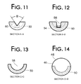
- FIG. 14 shows a cross-sectional view of the head 37 of the integrally formed hammer 36 taken at an 81 degree angle in relation to the horizontal axis of the v-shaped nail shaft groove 60 along the line D-D of FIG. 10 .
Landscapes
- Engineering & Computer Science (AREA)
- Mechanical Engineering (AREA)
- Percussive Tools And Related Accessories (AREA)
- Portable Nailing Machines And Staplers (AREA)
Abstract
The present invention is a manual nailing tool configured to provide a user with improved functional advantages over prior art hammers. It manually drives a substantial or predetermined amount of a fastener, such as an 8.89 cm (3½ inch) common nail, into a work piece with one hand using one striking action. The unique configuration of the integrally formed nail-starter and angled strike face closely combines the nail-starter function with a full force, sustained first strike on the nail head. The hammer is also configured with a unique head shape and strike face to improve striking power and facilitate a stronger and more direct impact force on the nail head.
Description
The present invention relates to hammers, and more particularly to a hammer with a unique head shape and improved one-handed nailing configuration.
Conventional hammers typically include a head and a handle. During use, a strike surface disposed on the head of the hammer is configured to strike against an object, such as a nail. Placing the nail with fewer strikes, with fewer failures, less concussive vibration and less energy output from the user are some objectives of hammer makers.
The common use of nail-starters on hammers has partially overcome the problem of requiring two hands to start a nail and hence removed some of the risk of injury to fingers. Many available hammers have a nail-starter located on the top front portion of the head. A lateral groove, configured to a length of at least 3.5 cm (1⅜ in.) from bell face to partial nail starter face, with a recessed magnet that retains the nail shank. The nail head rests in a generally rounded opening with a gradually sloping partial strike face that extends upward, supporting only a portion of the common nail head. This partial strike face is constructed so as to apply a limited amount of force to the nail head before the nail slides out from the nail head opening and loses contact. Hence the nail shaft is implanted to a shallow depth within the work piece surface. It is an acceptable, but not a consistently reliable means of nail starting and this is perhaps why it often referred to as an optional hammer feature, (eg., U.S. Pat. No. 8,047,099 B2) which states: The nail starter arrangement that includes the groove 64, magnet 67, and the surface 69 are optional.
There are a number of prior art nailing tools that have approached the problem of placing a nail that has been retained by the hammer. One technique, used in U.S. Pat. No. 5,894,764, confines and therefore restricts the nail head movement with both a vertical and horizontal wall and is only capable of a placing the nail to limited depth in a work piece. This typifies the fixed nail head nail starter method, whereby any nail depth placement in the work piece more than a minimal amount can result in a bent head, bent nail shaft or misdirected nail shaft. There are a number of limited nail starter methods and tools available, including commonly available nail-starters disposed on typical nailing hammers. Some relevant prior art that employ typical and alternate methods are:
- Pat. US 20110314971 A1
Which incorporates a nail magazine and mechanism to deliver nails. - U.S. Pat. No. 4,273,172 A
Which offers a limited force strike with a restricted nail head. - U.S. Pat. No. 2,597,876 A
Which offers a fixed head holder and limited depth placement of the shaft. - U.S. Pat. No. 4,193,433 A
Which retains the nail head with a hook beneath claw and offers limited nail shaft depth. - U.S. Pat. No. 6,301,996 B1
Which offers a limited depth with a multiple angle restriction upon the nail head.
These methods either confine and restrict the nail head or deliver a limited glancing strike. If the nail head is restricted the friction and forces that act upon the nail head cause it to be misdirected or cause the nail shaft to bend. The limited glancing strike of the typical partial strike face nail-starters can only drive the nail shaft in to a limited depth. These nail-starters are configured with only a limited amount of weight directly behind the partial nail head strike face.
When using the typical integrally formed nail-starter, the second strike, after initially planting the nail, is critical. The shallow depth of the initial nail start makes the successive strike, usually the most forceful, also the most likely to produce failure. This second blow requires more skill and accuracy to ensure an acceptable continuation of the nail placement, sometimes resulting in bent nail shafts or nails completely ejected from the work piece. If the second strike is successful it is commonly followed by a number of additional strikes, each one having a level of difficulty and having the possibility of bending or misdirecting the nail. The total number of strikes required is usually between 4 and 6, depending on, among other factors, nail size and desired depth.
Magnetic face specialty tools, usually referred to as tack hammers, roof paper hammers or upholstering hammers, have existed for more than one hundred years. These tools require specialized fasteners that typically have one or more of the following attributes; sharper points, shorter shafts, reinforced heads and/or oversized heads. Some prior art examples of tack hammers are as follows:
- Magnetic tack-hammer U.S. Pat. No. 840,441 A
- Magnetic tack-hammer U.S. Pat. No. 710,615 A
- Tack hammer U.S. Pat. No. 2,433,223 A
- Nail or tack holding attachment for hammers U.S. Pat. No. 469,710 A
- Magnetic roofing hammer U.S. Pat. No. 20030140734 A1
- Coil Nailer U.S. Pat. No. 20110049215 A1
Nail length is also an issue with typical nail starters. In order to function the nail length must be greater than the distance from the nail-starter strike face to the hammer strike face. Typically nails shorter than 3.8 cm (1½ in.) cannot utilize the common bell head nail starter.
Another problem with commonly used hammers is that they require a multitude of strikes in order to place the nail in a surface to a predetermined depth. Typically, said depth is more than 80 percent of the nail shaft length. Transporting the hammer weight in an arcing motion for a multitude of strikes in order to achieve this depth causes muscle stress and fatigue in the user.
An additional problem with repeated hammer face to nail head strikes is twist and vibration. Common hammer handles have a tendency to transfer torque (the twisting across the longitudinal axis of the handle) and kinetic energy caused by metal impacting metal to the user when a nail head is struck. This problem is compounded by the fact that the most control is required at the moment of impact between hammer face and nail head. The user must grip the handle the tightest at that time. This is when the most kinetic energy and twist occur within the handle, creating faster fatigue and adding more muscle stress to the user.
The following is a list of relevant prior art:
- U.S. Pat. No. 20120036965 A1
- U.S. Pat. No. 7,404,346 B2
- U.S. Pat. No. 4,667,747 A
- U.S. Pat. No. 3,788,373 A
- EP Pat. No. 2517837 A2
This embodiment of the present invention overcomes these problems by combining the nail-start strike and first full strike into one continuous action. Among other factors, it is the freedom of movement between nail head and striking surface afforded by the present invention which thereby allows the nail to be struck with full force. The nail shaft and nail head remain in their original uniform configuration and transverse directly into the work piece. Hence the nail is placed more consistently, with more reliability and with fewer strikes. Since there are fewer strikes required, and commonly only two metal on metal strikes, there is less energy output from the user and less concussive vibration.
This embodiment of the present invention is also configured with the preferred distance of 15 mm (⅝ in.) from the front edge, (horizontal cylinder segment strike-face), to the nail-starter strike face. Therefore, said embodiment provides a means for placing any nails minimally longer than 15 mm (⅝ in.). The 15 mm horizontal cylinder segment also provides a means to place nails in one strike to a depth whereby 15 mm of the nail is all that remains above the work piece surface.
These and other advantages of the present invention will be readily apparent to those of ordinary skill in the art upon a reading of the following detailed description of presently preferred, but nonetheless illustrative, embodiments of the present invention when taken in conjunction with the accompanying drawings. In this respect, before explaining the current embodiment of the invention in detail, it is to be understood that the invention is not limited in its application to the details of construction and to the arrangements of the components set forth in the following description or illustrated in the drawings. The invention is capable of other embodiments and of being practiced and carried out in various ways. Also, it is to be understood that the phraseology and terminology employed herein are for the purpose of descriptions and should not be regarded as limiting.
- 36—hammer
- 37—head
- 38—handle
- 40—upper handle portion
- 42—lower handle portion
- 43—butt-end portion
- 46—nail-starter strike face neck
- 48—nail-starter strike face
- 50—horizontal cylinder segment
- 52—horizontal cylinder segment strike-face
- 53—horizontal cylinder segment chamfer
- 54—magnet
- 56—magnet opening
- 58—semi-circular nail head opening
- 60—v-shaped nail shaft groove
- 62—head body
- 64—claw nail remover
- 66—bell neck
- 68—bell
- 70—bell strike face
- 71—bell chamfer
- 72—lower handle covering
- 74—front finger grip area
- 76—rear finger grip area
- 78—nail
One embodiment of the present invention consists of a curved head 37 disposed on the upper handle portion 40 of a curved handle 38. The curved nail-starter strike face neck 46 tapers so as to be reducing in diameter as it extends away from the center weight area of the head 37 and towards the nail-starter strike face 48. Said curved neck then extends further as a horizontal cylinder segment 50. In this segment a v-shaped nail shaft groove 60 with a recessed magnet 54 retains the nail while it is transported to the work piece surface in a typical manual nailing action.
The hammer 36 includes the overall length dimension (OAL). In one embodiment, as shown in FIGS. 4 and 5 , the overall length dimension (OAL) of the hammer 36 is measured along (or relative to) a central vertical axis A-A of the hammer 36. The (OAL) of one embodiment of the present invention as measured along the axis A-A is preferably 38-45 cm (15-18 inches).
In one embodiment, as shown in FIGS. 6 and 7 the head 37 is configured with a curved nail-starter strike face neck 46 tapering so as to be reducing in diameter as it extends away from the center weight area of the head 37 and towards the nail-starter strike face 48. The head 37 is generally curved whereby the horizontal center axis aligns with a typical arcing swing plane of the user when driving a nail into a work piece. The nail-starter strike face 48 diameter, as shown in FIG. 14 with a sectional view taken along the line D-D of FIG. 10 , to head body 62 diameter is configured with a ratio of 1:2.2.
In one embodiment, the head 37 of the hammer 36 is integrally formed with the upper handle portion 40, as shown in FIGS. 1-5 . The integrally formed handle 38 is made of metal, a composite material, or a synthetic material. In another embodiment, the head 37 and the handle 38 are formed separately and then connected to one another. Any suitable manner of connecting the head 37 and handle 38 may be employed. In this embodiment, the handle 38 shaft can be made from a different material than the head 37, such as wood, aluminum, a plastic material, a fiberglass material, or other suitable material.
As shown in FIGS. 1-5 , the hammer 36 includes a manually engageable lower handle covering 72. In one embodiment, the lower handle covering 72 is simply the outer surface of the handle material (e.g., wood or metal). In another embodiment, the manually engageable lower handle covering 72 of the hammer 36 is molded onto an inner or core portion of the lower handle portion 40. In one embodiment, the lower handle covering 72 is made of a rubber based material, a plastic based material or other suitable material. Optionally, the lower handle covering 72 can be ergonomically shaped. For example, a plurality of ridges spaced longitudinally along the front finger grip area 74 and the rear finger grip area 76. As shown in FIGS. 1-5 , the lower handle covering 72 ergonomically includes an extended toe on the front facing edge of a butt-end portion 43.
The upper handle portion 40 is configured likewise to provide durability and/or strength. It is configured with an I-shape cross sectional profile to provide a beneficial distribution of mass. The I-shape cross-sectional profile includes front and rear flanges and connecting web. Front flange preferably provides a broad surface adapted to reduce damage to handle 38 and/or a target caused by striking contact there-between, such as due to an overstrike. Web preferably resists bending and provides strength for handle 38 to allow generation and delivery of substantial striking forces by striking surface.
Yet another embodiment would configure the head body 62 in an increased aerodynamic, non-spherical shape, whereby the generally curving and tapered nail-starter strike face neck 46 transverses the bilateral axis of the head 37 and upper handle portion 40 and thereby extends as the bell neck of the adjacent strike face bell.
As shown in the partial views of FIGS. 8-10 , a grooved horizontal cylinder segment 50 extends from the lower portion of the nail-starter strike face neck 46. FIG. 8 shows a magnet 54 is located in the opening 56 of the v-shaped nail shaft groove 60. The magnet opening is 5 mm ( 3/16 in.) in diameter and with the perimeter disposed 2 mm ( 1/16 in.) from the front wall of the semi-circular nail head opening 58. The groove 60 is constructed and arranged to receive and retain a nail 78, (shown in dashed lines in FIG. 10 ), therein when the nail 78 is disposed in an initial nail driving position to facilitate the start of a nail driving operation.
Also shown in FIGS. 8-10 , is a semi-circular nail head opening 58 disposed between the v-groove 60 and the nail-starter strike face 48. Said opening is constructed and arranged to provide open space for the head of a nail 78. Thus, the v-groove 60 and the magnet 54, combined with the force and momentum of the hammer 36, act together to position and to initially connect the nail 78 with a work piece. The nail-starter strike face 48 is constructed and arranged at an angle of 81 degrees in relation to the v-groove longitudinal axis. The width of the nail head opening 58 as measured along the longitudinal center axis of the neck is 4 mm (⅛ in.).
Also shown in FIG. 17 , indicated by the broken line marked U, is the distance between the nail-starter strike face 48 and the bell strike face 70. For the purpose of OAL, measurement of said U shall represent head 37 length. The ratio of U to handle length in this embodiment of the present invention is 1:2.25
While these descriptions contain many specificities, they should not be construed as limitations on the scope, but rather as an exemplification of one (or several) embodiment(s) thereof. Many other variations are possible.
Other Advantages of the Invention
Nail insertion depth is determined by the distance the horizontal cylinder segment 50 extends outward from the nail-starter strike face 48. In some instances it is beneficial to predetermine the depth to which nails are implanted into the work piece. Hence the horizontal cylinder segment 50 may be configured for alternate nail starter depths.
Another advantage of this embodiment of the present invention is the reduction of torque and vibration effects experienced by the user. Common hammer handles have a tendency to transfer torque (the twisting across the longitudinal axis of the handle) and kinetic energy to a user's hand when a work piece is impacted. In order to maintain force direction and tool positioning, the user grips the handle more firmly while impacting the work piece. This embodiment of the present invention allows the user to do the opposite. Once the vertical descent motion has been initiated the user can loosen their grip on the handle 38 and allow the head 37 to implant the nail while only minimally maintaining contact with the handle 38 so as to guide it. The proximity of nail-starter strike face 48 to nail head thereby transfers less vibration and spread of kinetic energy.
Summation
Among various other advantages this tested embodiment of the present invention surpasses many objectives of prior art nailing hammer and nail-starter hammers. It places a nail deeper into a work piece with the first strike. It also places the nail more consistently and reliably with fewer strikes, and is capable of placing the nail to a predetermined depth with one strike.
Claims (9)
1. A hammer (36) comprising:
a handle (38), the handle having an upper handle portion (40), and a lower handle portion (42): and a head (37) disposed on the upper handle portion (40);
the head (37) having a centrally configured head body (62) that is integrally formed with the upper handle portion,
wherein the head (37) is comprised of a curved and tapering nail-starter strike face neck (46) of a predetermined length,
wherein the nail-starter strike face neck has a nail-starter strike face (48), configured at a predetermined angle and the lower portion of the nail-starter strike face neck (46) further extends as a horizontal cylinder segment (50),
wherein is configured a groove and magnet (54) to arrange and affix a nail thereon, a semi-circular nail head opening (58) comprising a shoulder and configured to receive the nail head in a position between the shoulder and the nail-starter strike face (48), and
wherein the horizontal cylinder segment (50) includes a convex strike face (52) in both horizontal and vertical directions, characterized in that a chamfer (53) is disposed along the edges of the strike face (52); and
wherein the adjacent end of the hammer (36) head (37) is configured with a bell neck (66) and bell (68), wherein the bell (68) includes a convex bell strike surface (70) in both horizontal and vertical directions, characterized in that a chamfer (71) is disposed along the edges of the strike face;
and a bifurcated claw nail remover (64) disposed on top of the head (37).
2. The hammer (36) of claim 1 , wherein the nail-starter strike face neck (46) tapers at a reducing diameter as it extends away from a center of the head body (62) and towards the nail-starter strike face (48).
3. The hammer (36) of any one of the preceding claims, wherein the nail-starter strike face is generally round shaped comprising a predetermined diameter and having the head disposed directly behind said nail-starter strike face.
4. The hammer (36) of claim 1 , wherein the head (37) is laterally offset a predetermined distance (H) relative to a vertical center line (Y) of the lower handle portion (42).
5. The hammer (36) of claim 4 , wherein the upper handle portion (40) is generally curved as it transverses upward to attach with a bottom center of the head (37).
6. The hammer (36) of claim 1 , wherein the upper handle portion (40) comprises an I-shape cross-sectional profile having front and rear flanges, and a center web.
7. The hammer (36) of claim 1 , wherein the nail-starter strike face is angled preferably between 75 and 85 degrees relative to a horizontal plane of the nail-starter strike face neck.
8. The hammer (36) of claim 1 , wherein the handle (38) comprises a metal shaft and disposed with a covering of a different material on top of the metal shaft, and wherein the covering comprises at least one of indents, ridges and textures on a front and a rear surface of the covering.
9. The hammer (36) of claim 1 , wherein the groove is a v-shaped nail shaft groove (60) comprising nail shaft support walls wherein the nail shaft support walls are angled to form a 60 degree vertical wedge.
Priority Applications (1)
| Application Number | Priority Date | Filing Date | Title |
|---|---|---|---|
| US14/185,598 US9682467B2 (en) | 2014-02-20 | 2014-02-20 | Nail-driving hammer |
Applications Claiming Priority (1)
| Application Number | Priority Date | Filing Date | Title |
|---|---|---|---|
| US14/185,598 US9682467B2 (en) | 2014-02-20 | 2014-02-20 | Nail-driving hammer |
Publications (2)
| Publication Number | Publication Date |
|---|---|
| US20170001292A1 US20170001292A1 (en) | 2017-01-05 |
| US9682467B2 true US9682467B2 (en) | 2017-06-20 |
Family
ID=57682834
Family Applications (1)
| Application Number | Title | Priority Date | Filing Date |
|---|---|---|---|
| US14/185,598 Expired - Fee Related US9682467B2 (en) | 2014-02-20 | 2014-02-20 | Nail-driving hammer |
Country Status (1)
| Country | Link |
|---|---|
| US (1) | US9682467B2 (en) |
Cited By (2)
| Publication number | Priority date | Publication date | Assignee | Title |
|---|---|---|---|---|
| US20180001460A1 (en) * | 2016-06-30 | 2018-01-04 | Daniel Ray Foucault | Device for applying railroad anchors |
| US20240042588A1 (en) * | 2020-01-10 | 2024-02-08 | Milwaukee Electric Tool Corporation | Hammer |
Families Citing this family (6)
| Publication number | Priority date | Publication date | Assignee | Title |
|---|---|---|---|---|
| US11891895B1 (en) | 2014-04-23 | 2024-02-06 | The Sollami Company | Bit holder with annular rings |
| TWI611882B (en) * | 2016-01-26 | 2018-01-21 | 施瑞源 | Force limiting damping device |
| US11279012B1 (en) * | 2017-09-15 | 2022-03-22 | The Sollami Company | Retainer insertion and extraction tool |
| US12345158B1 (en) | 2019-06-20 | 2025-07-01 | The Sollami Company | Bit tip insert |
| IT202000008107A1 (en) * | 2020-04-17 | 2020-07-17 | Cosimo Romano | Hygienic protection device for opening / closing and touch |
| FI4177011T3 (en) * | 2021-11-05 | 2024-08-30 | Fiskars Finland Oy Ab | Axe and a method for manufacturing an axe |
Citations (24)
| Publication number | Priority date | Publication date | Assignee | Title |
|---|---|---|---|---|
| US29760A (en) * | 1860-08-28 | Improvement in hammers | ||
| US63106A (en) * | 1867-03-19 | George selsoe | ||
| US303230A (en) * | 1884-08-05 | Hammer for holding and driving tacks | ||
| US392515A (en) * | 1888-11-06 | Tag k- hammer | ||
| US506935A (en) * | 1893-10-17 | Tinsmith s tool | ||
| US812947A (en) * | 1904-05-18 | 1906-02-20 | Herman E E Molkenthin | Combination-tool of the hammer type. |
| US2597876A (en) * | 1949-11-17 | 1952-05-27 | Yervant H Kurkjian | Magnetic nail-holding hammer |
| FR1335243A (en) * | 1962-08-09 | 1963-08-16 | Hammer with a built-in magnet | |
| US3796244A (en) * | 1972-09-25 | 1974-03-12 | B Florian | Double headed hammer |
| US3987828A (en) * | 1975-05-21 | 1976-10-26 | Matheis John L | Hammer |
| US4193433A (en) * | 1978-06-20 | 1980-03-18 | Sickler Jack R | Nail holding hammer |
| US4273172A (en) * | 1980-05-12 | 1981-06-16 | Hoosier Jack D | Nail holding hammer head |
| US4367778A (en) * | 1980-10-28 | 1983-01-11 | Ray Bradbury | Nail driver accessor having a nail holder mechanism |
| US4465115A (en) * | 1983-03-24 | 1984-08-14 | Palomera Louis M | Hammerhead |
| US5027677A (en) * | 1989-02-13 | 1991-07-02 | John Rallo | Electrician's utility hammer |
| US5988020A (en) * | 1998-01-05 | 1999-11-23 | Johnson; Ray W. | Hammerhead |
| US6301996B1 (en) * | 1999-04-08 | 2001-10-16 | Dennis Ellsworth Crawford | Nail-starting hammer head |
| US6339974B1 (en) * | 1998-03-16 | 2002-01-22 | Josef Kotschner | Carpenter hammer |
| US20030089203A1 (en) * | 2001-11-15 | 2003-05-15 | Wu Shu Te | Hammer loadable with different sizes of nails |
| US6829966B1 (en) * | 2002-05-16 | 2004-12-14 | Robert M. Bramuchi | Track fastening hammer |
| US20050115365A1 (en) * | 2002-10-31 | 2005-06-02 | Nau Tevita T. | Dual headed hammer |
| US20070089571A1 (en) * | 2005-10-21 | 2007-04-26 | Yung-Shou Chen | Hammer having a side working face |
| US20100116096A1 (en) * | 2008-05-06 | 2010-05-13 | Jared Hanlon | Striking tool |
| US20110314971A1 (en) * | 2009-12-16 | 2011-12-29 | Matthew Nicosia | One armed hammer and system |
-
2014
- 2014-02-20 US US14/185,598 patent/US9682467B2/en not_active Expired - Fee Related
Patent Citations (24)
| Publication number | Priority date | Publication date | Assignee | Title |
|---|---|---|---|---|
| US29760A (en) * | 1860-08-28 | Improvement in hammers | ||
| US63106A (en) * | 1867-03-19 | George selsoe | ||
| US303230A (en) * | 1884-08-05 | Hammer for holding and driving tacks | ||
| US392515A (en) * | 1888-11-06 | Tag k- hammer | ||
| US506935A (en) * | 1893-10-17 | Tinsmith s tool | ||
| US812947A (en) * | 1904-05-18 | 1906-02-20 | Herman E E Molkenthin | Combination-tool of the hammer type. |
| US2597876A (en) * | 1949-11-17 | 1952-05-27 | Yervant H Kurkjian | Magnetic nail-holding hammer |
| FR1335243A (en) * | 1962-08-09 | 1963-08-16 | Hammer with a built-in magnet | |
| US3796244A (en) * | 1972-09-25 | 1974-03-12 | B Florian | Double headed hammer |
| US3987828A (en) * | 1975-05-21 | 1976-10-26 | Matheis John L | Hammer |
| US4193433A (en) * | 1978-06-20 | 1980-03-18 | Sickler Jack R | Nail holding hammer |
| US4273172A (en) * | 1980-05-12 | 1981-06-16 | Hoosier Jack D | Nail holding hammer head |
| US4367778A (en) * | 1980-10-28 | 1983-01-11 | Ray Bradbury | Nail driver accessor having a nail holder mechanism |
| US4465115A (en) * | 1983-03-24 | 1984-08-14 | Palomera Louis M | Hammerhead |
| US5027677A (en) * | 1989-02-13 | 1991-07-02 | John Rallo | Electrician's utility hammer |
| US5988020A (en) * | 1998-01-05 | 1999-11-23 | Johnson; Ray W. | Hammerhead |
| US6339974B1 (en) * | 1998-03-16 | 2002-01-22 | Josef Kotschner | Carpenter hammer |
| US6301996B1 (en) * | 1999-04-08 | 2001-10-16 | Dennis Ellsworth Crawford | Nail-starting hammer head |
| US20030089203A1 (en) * | 2001-11-15 | 2003-05-15 | Wu Shu Te | Hammer loadable with different sizes of nails |
| US6829966B1 (en) * | 2002-05-16 | 2004-12-14 | Robert M. Bramuchi | Track fastening hammer |
| US20050115365A1 (en) * | 2002-10-31 | 2005-06-02 | Nau Tevita T. | Dual headed hammer |
| US20070089571A1 (en) * | 2005-10-21 | 2007-04-26 | Yung-Shou Chen | Hammer having a side working face |
| US20100116096A1 (en) * | 2008-05-06 | 2010-05-13 | Jared Hanlon | Striking tool |
| US20110314971A1 (en) * | 2009-12-16 | 2011-12-29 | Matthew Nicosia | One armed hammer and system |
Cited By (3)
| Publication number | Priority date | Publication date | Assignee | Title |
|---|---|---|---|---|
| US20180001460A1 (en) * | 2016-06-30 | 2018-01-04 | Daniel Ray Foucault | Device for applying railroad anchors |
| US20240042588A1 (en) * | 2020-01-10 | 2024-02-08 | Milwaukee Electric Tool Corporation | Hammer |
| US12246425B2 (en) * | 2020-01-10 | 2025-03-11 | Milwaukee Electric Tool Corporation | Hammer |
Also Published As
| Publication number | Publication date |
|---|---|
| US20170001292A1 (en) | 2017-01-05 |
Similar Documents
| Publication | Publication Date | Title |
|---|---|---|
| US9682467B2 (en) | Nail-driving hammer | |
| US8770548B2 (en) | Striking tools | |
| US8387486B2 (en) | Striking tool | |
| US8567760B2 (en) | Prying tools | |
| US4482132A (en) | Nail removing hammer | |
| US9718179B1 (en) | Striking tool having improved head and handle attachment | |
| US4273172A (en) | Nail holding hammer head | |
| US20090127521A1 (en) | Fastener extraction tool | |
| EP3235598A1 (en) | Hammer with recessed blade | |
| US8109178B2 (en) | Side-load nail holding hammer | |
| US4718313A (en) | Hammer head for a hammer | |
| US6299136B1 (en) | High brow claw hammer head | |
| US20100307295A1 (en) | Nail ripper | |
| US20060021474A1 (en) | Double headed striking tool | |
| CN211466272U (en) | A nail correction aid for construction engineering | |
| US6772657B2 (en) | Nail-setting claw hammer head | |
| US20020194741A1 (en) | Non-threaded fastener removal tool | |
| US1914256A (en) | Staple and tool to facilitate its application | |
| US20010029633A1 (en) | Hammerhead with nail straightening holes | |
| CA2280368A1 (en) | Combination construction tool | |
| US20010025949A1 (en) | Nail extractor method and apparatus | |
| US20170129087A1 (en) | Power gun fabric and staple removal bits | |
| JP4443938B2 (en) | Manual nailer | |
| CN211362141U (en) | Claw hammer | |
| CA2454638C (en) | Hammer or tool with nail remover |
Legal Events
| Date | Code | Title | Description |
|---|---|---|---|
| STCF | Information on status: patent grant |
Free format text: PATENTED CASE |
|
| FEPP | Fee payment procedure |
Free format text: MAINTENANCE FEE REMINDER MAILED (ORIGINAL EVENT CODE: REM.); ENTITY STATUS OF PATENT OWNER: SMALL ENTITY |
|
| LAPS | Lapse for failure to pay maintenance fees |
Free format text: PATENT EXPIRED FOR FAILURE TO PAY MAINTENANCE FEES (ORIGINAL EVENT CODE: EXP.); ENTITY STATUS OF PATENT OWNER: SMALL ENTITY |
|
| STCH | Information on status: patent discontinuation |
Free format text: PATENT EXPIRED DUE TO NONPAYMENT OF MAINTENANCE FEES UNDER 37 CFR 1.362 |
|
| FP | Lapsed due to failure to pay maintenance fee |
Effective date: 20210620 |