US9681306B2 - Method for selecting master CM in coexistence network - Google Patents
Method for selecting master CM in coexistence network Download PDFInfo
- Publication number
- US9681306B2 US9681306B2 US14/382,713 US201214382713A US9681306B2 US 9681306 B2 US9681306 B2 US 9681306B2 US 201214382713 A US201214382713 A US 201214382713A US 9681306 B2 US9681306 B2 US 9681306B2
- Authority
- US
- United States
- Prior art keywords
- management device
- devices
- master
- tvws
- coexistence
- Prior art date
- Legal status (The legal status is an assumption and is not a legal conclusion. Google has not performed a legal analysis and makes no representation as to the accuracy of the status listed.)
- Expired - Fee Related, expires
Links
Images


Classifications
-
- H—ELECTRICITY
- H04—ELECTRIC COMMUNICATION TECHNIQUE
- H04W—WIRELESS COMMUNICATION NETWORKS
- H04W16/00—Network planning, e.g. coverage or traffic planning tools; Network deployment, e.g. resource partitioning or cells structures
- H04W16/14—Spectrum sharing arrangements between different networks
-
- H—ELECTRICITY
- H04—ELECTRIC COMMUNICATION TECHNIQUE
- H04W—WIRELESS COMMUNICATION NETWORKS
- H04W4/00—Services specially adapted for wireless communication networks; Facilities therefor
- H04W4/02—Services making use of location information
-
- H—ELECTRICITY
- H04—ELECTRIC COMMUNICATION TECHNIQUE
- H04W—WIRELESS COMMUNICATION NETWORKS
- H04W4/00—Services specially adapted for wireless communication networks; Facilities therefor
- H04W4/06—Selective distribution of broadcast services, e.g. multimedia broadcast multicast service [MBMS]; Services to user groups; One-way selective calling services
- H04W4/08—User group management
-
- H—ELECTRICITY
- H04—ELECTRIC COMMUNICATION TECHNIQUE
- H04W—WIRELESS COMMUNICATION NETWORKS
- H04W72/00—Local resource management
- H04W72/04—Wireless resource allocation
- H04W72/044—Wireless resource allocation based on the type of the allocated resource
- H04W72/0453—Resources in frequency domain, e.g. a carrier in FDMA
-
- H—ELECTRICITY
- H04—ELECTRIC COMMUNICATION TECHNIQUE
- H04W—WIRELESS COMMUNICATION NETWORKS
- H04W28/00—Network traffic management; Network resource management
- H04W28/02—Traffic management, e.g. flow control or congestion control
- H04W28/08—Load balancing or load distribution
-
- H—ELECTRICITY
- H04—ELECTRIC COMMUNICATION TECHNIQUE
- H04W—WIRELESS COMMUNICATION NETWORKS
- H04W84/00—Network topologies
- H04W84/18—Self-organising networks, e.g. ad-hoc networks or sensor networks
- H04W84/20—Leader-follower arrangements
Definitions
- the present invention relates to a reconfiguration mechanism of a coexistence topology using centralized and distributed coexistence topologies, and more particularly, to a method and apparatus for selecting a master device for the reconfiguration.
- a frequency sharing method has been in the spotlight as a scheme capable of solving the above problems.
- Advocates for frequency sharing consider that a current shortage of frequencies is caused by a conventional partition type frequency management method and can be solved via a sharing method although a frequency looks deficient on the frequency distribution table.
- frequency sharing is not a new concept but a method for resource management of a communication system in terms of technology, and various frequency sharing methods have been applied.
- Examples of the frequency sharing method may also include a cellular method, time division multiple access (TDMA), code division multiple access (CDMA), etc. that are conventionally and widely used.
- interference can be effectively suppressed under the same technological standard or control of service providers.
- a distributional sharing method that has been recently introduced, for example, cognitive radio (CR) likely to cause tragedy of commons and harmful interference due to indiscriminate use of frequencies. Accordingly, the method can cause problems in terms of frequency management and protection of existing users and contradict with the intent of a market-based frequency policy as the current tendency of a frequency management system.
- CR cognitive radio
- a type of frequency sharing method can be classified according to a sharing ‘method’ and ‘subject and object’.
- coexistence and cooperative methods are considered as the sharing method.
- the sharing subject and object can be classified into sharing among equals in which a subject and an object have equivalent positions and primary-secondary sharing in which a primary user and a secondary user share a frequency.
- Resource allocation and interference avoidance are possible via organic cooperation among all users.
- Resource allocation and interference avoidance can be centrally performed via a base station (BS), etc. or may be distributively performed between users.
- BS base station
- Examples of the former may include a mobile communication system such as CDMA/TDMA methods and examples of the latter may include an ad-hoc system.
- mutual coexistence a case in which users separately perform interference avoidance without resource allocation using this common protocol can be referred to as mutual coexistence.
- Examples of the mutual coexistence (or simply coexistence) scheme may include a wireless local area network (LAN), a cordless phone, etc. as currently commercialized technologies and may also include overlay and underlay technologies.
- LAN wireless local area network
- cordless phone etc.
- overlay and underlay technologies Compared with the cooperative scheme, according to the coexistence scheme, resource allocation and interference control are passively intervened in terms of technologies, and thus, problems arise in that the probability of interference increases.
- a coexistence topology may be a centralized coexistence topology and a distributed coexistence topology.
- the centralized coexistence topology has global information for decision making and thus effectively manages interference.
- performance is degraded due to excessive computational overhead in proportion to the number of devices to be managed.
- the distributed coexistence topology requires low computational and communication overhead.
- local optimization is used, and thus, high interference can be caused.
- An object of the present invention devised to solve the problem lies in a condition for selection of a master coexistence manager (CM) for reconfiguration of a coexistence topology in associated with reconfiguration of the aforementioned coexistence topology for balancing interference and overhead.
- CM master coexistence manager
- the object of the present invention can be achieved by providing a method for requesting a server to select a master management device by a management device for coexistence of television white space (TVWS) devices in a television white space (TVWS), the method including checking whether a trigger condition of a process for selection of the master management device is satisfied, determining the management device as a candidate slave management device and other management devices as a candidate master management device when the trigger condition is satisfied, and initiating the process for selection of the master management device, wherein the trigger condition is based on a load balance parameter or geographical coverage parameter of the management device.
- TVWS television white space
- TVWS television white space
- the checking whether the trigger condition is satisfied may include comparing the load balance parameter and a reference value.
- the load balance parameter may be dependent upon the number of TVWS devices being controlled by the management device, N(t).
- the load balance parameter may be dependent upon the maximum number of TVWS devices which the management device controls, N max .
- the trigger condition may be represented as follows,
- N(t) is the number of TVBD devices being controlled by the management device
- N max is the maximum number of TVBD devices which the management device controls
- M trigger corresponds to a margin value for the trigger condition
- the checking whether the trigger condition is satisfied may include checking whether the geographical coverage parameter of the management device is included in a geographical coverage parameter of another management device.
- the geographical coverage parameter may be dependent upon a geographical location of the management device and a coverage radius of the management device.
- the geo-coverage parameter of the another management device may be acquired via a coexistence set information announcement (CoexistenceSetElementInformationAnnouncement) message for sharing coexistence set information received from the another management device.
- CoexistenceSetElementInformationAnnouncement CoexistenceSetElementInformationAnnouncement
- a method for selecting a master management device, by a server, among a plurality of management devices for coexistence of television white space (TVWS) devices in a TVWS including receiving a registration request message for registration or update registration of the TVWS devices from each of the plurality of management devices, performing the registration or update registration of the TVWS devices, checking whether a trigger condition of a process for selection of the master management device is satisfied for the plurality of management devices based on information contained in the registration request message, initiating the process for selection of the master management device when the trigger condition is satisfied, wherein the registration request message includes information about the maximum number of TVWS devices which the management device having transmitted the registration request message, a geo-location and a geo-coverage radius of the management device having transmitted the registration request message.
- TVWS television white space
- the trigger condition may be represented as follows:
- N(t) is the number of TVBD devices being controlled by the management device
- N max is the maximum number of TVBD devices which the management device controls
- M trigger corresponds to a margin value for the trigger condition
- the checking whether the trigger condition is satisfied may include comparing a load balance parameter and a reference value.
- the checking whether the trigger condition is satisfied may include checking whether the geographical coverage parameter of one management device is included in a geographical coverage parameter of another management device.
- the method may further include determining a specific management device as a candidate slave management device and other management devices as a candidate master management apparatus when the trigger condition for the specific management device among the management devices is satisfied.
- the method may further include checking whether the candidate master management device is capable of using the candidate slave management device as a slave device of the candidate master management device based on an internal decision condition when the process is initiated.
- the internal decision condition may be represented as follows, N B max >N A ( t )+ N B ( t )+ M criteria
- N A (t) is the number of TVWS devices being controlled by the candidate slave management device
- N B (t) is the number of TVWS devices being controlled by the candidate master management device
- N max B is the maximum number of TVWS devices which the candidate master management device controls
- M criteria corresponds to a margin value for the internal decision condition.
- CM master coexistence manager
- FIG. 1 is a block diagram illustrating a coexistence system according to an embodiment of the present invention
- FIG. 2 is a diagram illustrating concept of a method for selecting a master coexistence manager (CM) in a coexistence system with a centralized topology according to an embodiment of the present invention
- FIG. 3 is a diagram illustrating concept of a method for selecting a master CM in a coexistence system with a distributed topology according to an embodiment of the present invention
- FIG. 4 is a diagram illustrating concept of comparison between operations of coexistence systems with a centralized topology and a distributed topology according to an embodiment of the present invention
- FIG. 5 is a signal flowchart illustrating a method for allocating a resource by a master CM in a coexistence system with a centralized topology according to an embodiment of the present invention
- FIG. 6 is a signal flowchart illustrating a method for allocating a resource by a master CM in a coexistence system with a distributed topology according to an embodiment of the present invention
- FIG. 7 is a signal flowchart illustrating a method for selecting a master CM in a coexistence system with a centralized topology according to an embodiment of the present invention
- FIG. 8 is a signal flowchart illustrating a method for selecting a master CM in a coexistence system with a distributed topology according to an embodiment of the present invention
- FIG. 10 is a diagram illustrating an example in which a hierarchical structure is formed and operated via enable/disable between heterogeneous CMs in a coexistence system according to an embodiment of the present invention
- FIG. 12 is a flowchart of a registration procedure according to an embodiment of the present invention.
- FIG. 13 illustrates a master management device selecting method according to an embodiment of the present invention.
- the TVWS device and the TVBD or TVBD device are interchangeable, the TVWS network and the TVBD network are also interchangeable termed, and these terms may correspond to an entity referred to as a WSO.
- a structure of a coexistence system that is, an 802.19 system includes three logical entities and six logic interfaces.
- the logical entities may be installed or mounted on respective physical devices.
- the logical entities may be embodied as hardware using the devices on which the logical entities are installed or mounted.
- the logical entity may be termed an apparatus or device in this specification including the claims.
- a coexistence manager (CM) 20 may be termed a “management apparatus” and a coexistence discovery and information server (CDIS) 10 may be simply termed a “server”.
- CDIS coexistence discovery and information server
- the three logical entities are each defined as the CM 20 , a coexistence enabler (CE) 30 , and a coexistence database (CD) or coexistence discovery and information server (CDIS) 10 according to function.
- the six logic interfaces are each defined as an interface A, an interface B 1 , an interface B 2 , an interface B 3 , an interface C, and an interface D according to whether the logic interface interfaces with another logical entity of 802.19.1.
- TV white space refers to a vacant frequency band that is not used by a broadcaster in VHF and UHF frequency bands that are distributed for TV broadcast and refers to an unlicensed band that can be used by any user when he or she satisfies conditions of radio wave regulations of the government.
- the TV white space refers to a vacant band for prevention of frequency interference between broadcasters and a frequency band that is not used for each region or an area to which radio waves for broadcast do not reach for each region from a spatial point of view, and refers to a vacant broadcast frequency in a time zone when a broadcaster does not broadcast at dawn from a temporal point of view.
- a TV whitespace includes VHF bands 54 to 60, 76 to 88, and 174 to 216 MHz and UHF bands 470 to 698 MHz that are allocated to a broadcast TV system.
- VHF bands 54 to 60, 76 to 88, and 174 to 216 MHz and UHF bands 470 to 698 MHz that are allocated to a broadcast TV system.
- operations are allowed for all unlicensed devices except for in some particular cases, but bands 54 to 60 MHz, 76 to 88 MHz, 174 to 216 MHz, and 470 to 512 MHz, only communication between fixed devices is allowed.
- a fixed device is a device that performs transmission from a fixed location.
- a TV white space device should not interfere with a TV viewer as a customer of a broadcaster, should not interrupt reception, and should not affect a wireless microphone device that communicates with low power using a portion of the band. In order satisfy this condition, the TV white space device requires the following technologies.
- the TV white space device may require technologies such as a spectrum sensing technology for recognizing a TV channel being used to protect a broadcast channel, a access protocol technology for database having position-based TV channel information, a coexistence technology between heterogeneous devices using a TVWS band, an intelligent and autonomous wireless access element technology for a variable radio channel, a security technology for subscriber authentication for radio channel protection and protection of DBs and users, etc.
- technologies such as a spectrum sensing technology for recognizing a TV channel being used to protect a broadcast channel, a access protocol technology for database having position-based TV channel information, a coexistence technology between heterogeneous devices using a TVWS band, an intelligent and autonomous wireless access element technology for a variable radio channel, a security technology for subscriber authentication for radio channel protection and protection of DBs and users, etc.
- the present invention will be described in terms of a coexistence technology between homogeneous or heterogeneous apparatuses (or devices) among these technologies.
- the CM 20 and the CE 30 are logical entities defined for coexistence between different wireless service providers or wireless systems that operate in an unlicensed state in a TVWS.
- the CM 20 is an entity for resource allocation in order to overcome an issue associated with an interface between CEs 30 connected to the CM 20 while providing a guideline and policy associated with coexistence for coexistence between different service providers and systems operating in a TVWS.
- the CE 30 may request and acquire information required for coexistence to and from the TVBD network or device 100 , convert structure change requests/commands and control information received from the CM 20 into TVBD-specific structure change requests/commands, and transmit the TVBD-specific structure change requests/commands to the TVBD network or device 100 .
- the TVBD network or device 100 refers to a user equipment for allowing use of a TV white space in the federal communication commission (FCC).
- the CM 20 may have a function of selecting a master CM by sharing information between various CMs, a function of generating a coexistence whitespace map having a distributed topology in order to effectively share frequency resources between different networks and systems, and a function of adjusting networks during management associated with TVWS coexistence.
- the CM 20 may be embedded in a device such as an access point (AP) or may be installed out of the device.
- a fixed device such as an access point (AP) may have a function of the CM 20 and may select and manage a master CM for mastering a set including devices that are spatially separated, a service provider, or a specific system.
- the master CM may be selected by the CD or CDIS 10 for allowing spatial reuse between spatially separated users.
- an interface map between CMs for resource allocation may be acquired as geo-location information or acquired by further using and processing neighbor information acquired from CMs.
- the master CM may be selected via communication between the networks, and in the case of heterogeneous networks, the master CM may be selected via negotiation via the CD or CDIS 10 .
- a small size network compares a whitespace map (WM) of adjacent heterogeneous networks and a whitespace map (WM) of the small size network via the CM 20 and preferentially selects and uses a channel that cannot be used by adjacent networks, which can be adjusted by the CDIS 10 but can be distributively performed in a reverse order from the small size network.
- WM whitespace map
- WM whitespace map
- the CD or CDIS 10 may have a function of generating a coexistence whitespace map having a centralized topology in order to effectively sharing a frequency resource between different networks and systems, a function of controlling a plurality of operators during management associated with TVWS coexistence, and a function of selecting a master CM in order to reduce communication overhead between CMs and to overcome the coexistence issue.
- the CD or CDIS 10 may perform a function of calculating a coexistence contour in order to search for neighboring networks/systems, a function of redirecting a resource C-MAP according to a TVDB in order to the coexistence issue, a function of boosting opening of an interface between CMs to support search of CMs, and a function of collecting, synthesizing, and providing information for boosting of coexistence.
- the CD 10 may omnipotently distribute resources for resource allocation, may suggest a criteria of priority between CMs and control resource selection of each CM as an intermediary, or may function as a medium for sharing information between external and heterogeneous networks between CMs as a DB.
- the interface may be classified into three groups as illustrated in FIG. 1 .
- the interface may classified into interface B 1 , an interface B 2 , and an interface B 3 as an interface between 802.19.1 entities, an interface A as an interface between an 802.19.1 entity and a TVBD network/device, and an interface C and an interface D as an interface between an 802.19.1 entity and a TVWS database or an OME.
- the different interfaces in each group may be classified according to a using method thereof, a type of exchanged information, and underlying protocols.
- the interface A may be an interface between the CE 30 and the TVBD network or device 100 and may be used to receive information required for coexistence, configuration/information request for coexistence, configuration/measurement/information response for coexistence, and other information as necessary from the TVBD network or device 100 .
- Reconfiguration request/command and control information (corresponding to control information and coexistence request/command received from the CM), request/command associated with control of a measurement value, performed by the TVBD network or device 100 , information indicating available resources, and other information as necessary from the CE 30 to the TVBD network or device 100 .
- the interface B 1 may be an interface between the CE 30 and the CM 20 and may be used to provide information required for coexistence (information acquired from the TVBD network or device 100 ) and other information as necessary to the CM 20 from the CE 30 . Coexistence request/command and control information and other information as necessary may be provided to the CE 30 from the CM 20 .
- the interface B 2 may be an interface between the CM 20 and the CD or CDIS 10 and may be used to provide information required for a coexistence map, information required for a neighbor set, information required for registration/unenrollment, information required for searching (which is acquired by a currently used CM), information required for coexistence, and information as necessary to the CD or CDIS 10 from the CM 20 .
- Information indicated for a coexistence map, information indicated for a neighbor set, information indicated for a master CM, information required for search (which is acquired by another CM), information required for coexistence (which is acquired by another CM), and other information as necessary are provided to the CM 20 from the CD or CDIS 10 .
- the interface B 3 may be an interface between the CM 20 and a CM 21 and may be used to provide information and messages for searching and coexistence, information indicated for registration/unregistration (to a master CM from a CM or to a server CM from a device CM), information indicated for coexistence (to a master CM from a CM or to a device CM from a server CM), and other information to the CM 21 from the CM 20 .
- the interface C may be an interface between the TVBD device 100 and the TVWS database 200 and may be used to provide information indicated for an available channel to the TVBD device 100 from the TVWS DB 200 .
- the interface D may be an interface between the CM 20 and the OME 300 and may be used to provide network operation information associated with information of the CM 20 (e.g., limiting factors associated with management of spectrum policy/network) and other information as necessary from the OME 300 .
- the coexistence system described with reference to FIG. 1 may have various topologies and may be largely classified into a centralized topology, a distributed topology, an autonomous topology.
- the present invention will be described in terms of a coexistence system having centralized and distributed topologies.
- FIG. 2 is a diagram illustrating concept of a method for selecting a master CM in a coexistence system with a centralized topology according to an embodiment of the present invention.
- a CDIS 11 mainly stores and processes data and the CM 20 may function as a decision maker.
- the master CM 20 may control all networks or other UEs.
- one of TVBDs that interface with a network may be selected as the master CM 20 .
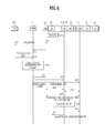
- FIG. 3 is a diagram illustrating concept of a method for selecting a master CM in a coexistence system with a distributed topology according to an embodiment of the present invention.
- the CDIS 11 or a coexistence database (CDB) 12 may boost opening of interfaces between CMs, and the CM 20 may exchange information required for coexistence and perform hierarchical or peer-to-peer decision making.
- CDB coexistence database
- the coexistence system of FIG. 3 may perform decision making via negotiation between CMs through an interface (the interface B 3 ) to determine a master CM as illustrated in FIG. 3( a ) or the CM 20 may request mediation to the CDIS 11 or a CDB 12 through an interface (the interface B 2 ) to perform decision making or determine a master CM as illustrated in FIG. 3( b )
- FIG. 4 is a diagram illustrating concept of comparison between operations of coexistence systems with a centralized topology and a distributed topology according to an embodiment of the present invention.
- a master (master or super) CM 40 may allocate independent channels to different CMs (or CEs), respectively.
- a coexistence whitespace map (CWM) may be used to indicate channels to be used.
- CMs e.g., a CM 1 and a CM 2
- the CM 20 may report/send priority information about available channels to CDB/CDIS or other CMs.
- a CWM may be used as channels to be selected by CMs.
- An 802.19.1 system needs to analyze acquired information, to perform coexistence determination, and to support various topologies.
- information may contain a bandwidth of each TVWS network or device, power limitation of each TVWS channel and an available channel list obtained from each TVWS network/device, and regulations, system parameters or pre-analyzed surrounding information, irrespective of a type of topology.
- FIGS. 5 and 6 are signal flowcharts of a method for allocating a resource by a master CM or a mater device in the coexistence systems with a centralized topology and a distributed topology described with reference to FIGS. 2 to 4 .
- FIG. 5 is a signal flowchart illustrating a method for allocating a resource by a master CM in a coexistence system with a centralized topology according to an embodiment of the present invention.
- the method for allocating a resource by the master CM 40 in one centralized topology may include steps S 15 to S 17 of requesting resources by an AP 50 , steps S 18 to S 21 of acquiring an available channel list from the TVBD 100 by the CDIS 11 to indicate the available channel list to the master CM 40 , and steps S 22 to S 24 of allocating a resource to the CM 20 by the master CM 40 .
- the CM 20 When an AP 50 is registered to the TVDB 100 and the CM 20 (S 11 to S 12 ), the CM 20 is registered to the master CM 40 (S 13 ), and the master CM 40 is registered to the CDIS 11 (S 14 ).
- the AP 50 requests the CM 20 for a resource via resource request (Resource (C-MAP) REQ) (S 15 )
- the CM 20 requests the master CM 40 for a neighbor list and information about C-MAP (S 16 )
- the master CM 40 requests the CDIS 11 for the neighbor list and the information about C-MAP (S 17 ).
- the CDIS 11 requests the TVDB 100 for an available TVWS channel list REQ, (S 18 ), receives a response to the request from the TVDB 100 (S 19 ), and calculates a neighbor or a neighbor set of the CM 20 and C-MAP (S 20 ).
- the CDIS 11 may notify the master CM 40 of C-MAP and a neighbor list of the CM 20 as results obtained via the step S 20 (S 21 ).
- the master CM 40 allocates the resource (C-MAP) based on the notification to the CM 20 (S 22 to S 23 ), and the CM 20 notifies the AP 50 of the C-MAP (S 24 ).
- FIG. 6 is a signal flowchart illustrating a method for allocating a resource by a master CM in a coexistence system with a distributed topology according to an embodiment of the present invention.
- the method for allocating a resource by the master CM 20 in one distributed topology may include steps S 35 to S 37 of requesting resources by an AP 50 , steps S 37 to S 40 of acquiring an available channel list from the TVBD 100 by the CDIS 11 to indicate the available channel list to the CM 20 , and steps S 41 and S 42 of negotiating a resource with other CMs (e.g., the CM 21 and the CM 22 ) by the CM 20 .
- steps S 35 to S 37 of requesting resources by an AP 50 steps S 37 to S 40 of acquiring an available channel list from the TVBD 100 by the CDIS 11 to indicate the available channel list to the CM 20
- steps S 41 and S 42 of negotiating a resource with other CMs e.g., the CM 21 and the CM 22
- the CM 20 When the AP 50 is registered to the TVDB 100 and the CM 20 (S 31 to S 33 ), the CM 20 is registered to the CDIS 11 (S 34 ). When the AP 50 requests the CM 20 for a resource via resource request (Resource REQ) (S 35 ), the CM 20 requests the CIDS 10 for neighbor list information and C-MAP (S 36 ).
- Resource REQ resource request
- the CDIS 11 requests the TVDB 100 for an available TVWS channel list REQ (S 37 ), receives a response to the request from the TVDB 100 (S 38 ), and calculates a neighbor set of the CM 20 and C-MAP (S 39 ).
- the CDIS 11 may notify the CM 20 of C-MAP and a neighbor list of CMs as results obtained via the step S 39 (S 40 ), and the CM 20 negotiates a resource with other CMs (e.g., the CM 21 and the CM 22 ) based on the notification (S 41 to S 42 ) and reallocates a resource C-MAP to the AP 50 (S 43 to S 44 ).
- FIGS. 7 and 8 are signal flowcharts illustrating a method for selecting a master CM (or a master device) in the coexistence systems with a centralized topology and a distributed topology described with reference to FIGS. 2 to 4 .
- FIG. 7 is a signal flowchart illustrating a method for selecting the master CM in a coexistence system with a centralized topology according to an embodiment of the present invention.
- the method for selecting the master CM by a centralized topology includes a step S 55 of receiving TV channel lists from the TVDB 100 by the CDIS 11 , steps S 56 and S 57 of calculating C-MAP and a neighbor of CMs by the CDIS 11 to select the master CM of CMs, and steps S 58 to S 60 of notifying the other CMs (the CM 20 and the CM 22 ) of the selection of the master CM by the CDIS 11 .
- the CM 20 is registered to the CDIS 11 (S 54 ).
- the CDIS 11 acquires information of an available TV channel list from the TVDB 100 (S 55 ).
- the TVDB 100 updates the available TV channel list at a regular interval.
- the CDIS 11 calculates C-MAP and a neighbor or neighbor set of CMs (e.g., the CM 20 and the CM 22 ) (S 56 ) to select the CM 21 as the master CM (S 57 ), and then notifies CMs of the selection of the master CM 40 (S 58 to S 60 ).
- the master CM 21 that is finally selected is a master of an AP (S 61 ).
- FIG. 8 is a signal flowchart illustrating a method for selecting the master CM in a coexistence system with a distributed topology according to an embodiment of the present invention.
- the method for selecting the master CM by a distributed topology includes a step S 75 of receiving channel lists from the TVDB 100 by the CDIS 11 , steps S 76 to S 79 of calculating C-MAP and a neighbor of CMs by the CDIS 11 and notifying CMs of the calculation result, and steps S 80 to S 82 of performing negotiation between CMs in order to select the master CM or a master device by each of the CMs.
- a master CM or a master device (BS, eNodeB, MS, etc.) is selected, and a network or device (or CM/CE of a device) that is not a mater CM or a mater device is controlled to be ON/OFF or disabled so as to adaptively support various types of structures.
- FIG. 9 is a diagram illustrating an example in which various structures can be adaptively supported via enable/disable between heterogeneous CMs in a coexistence system according to an embodiment of the present invention.
- CMs of a heterogeneous system that requires cooperation may adaptively support various types of structures ON/OFF, active/inactive, enable/disable, or the like between the CMs.
- FIG. 9( a ) when a structure between CMs of each heterogeneous system (e.g., a system A, a system B, and a system C) is formed as a peer-to-peer structure, it may be seen that an enabled CM 20 is operated as a controller of the disable CM 21 and CM 22 to form a tree structure via enable/disable, etc. between CMs, as illustrated in FIG. 9( b ) .
- FIG. 10 is a diagram illustrating an example in which a hierarchical structure is formed and operated via enable/disable between heterogeneous CMs in a coexistence system according to an embodiment of the present invention.
- a master CM may be selected via ON/OFF, active/inactive, enable/disable, or the like between the heterogeneous CMs to form a vertical relation, and each CM may perform decision making on networks of a horizontal layer and a lower layer of the CM.
- a cellular system may determine resource regions of the cellular system and a WLAN as a lower layer of the cellular system, and the WLAN may determine resource regions of the WLAN and a WPAN as a lower layer of the WLAN with respect to resources allocated from the cellular system.
- FIG. 11 illustrates a coexistence set information sharing procedure according to an embodiment of the present invention.
- a CM (a management device) may perform the coexistence set information sharing procedure when coexistence set information for one or more WSOs having coexistence set WSOs served by the CM and served by other one or more CMs is changed.
- the CM 21 may generate one or more coexistence set information announcement messages, for example, a CoexistenceSetElementInformationAnnouncement message.
- the number of the generated messages is equal to the number of CMs that serve WOSs in a coexistence set of WSOs, coexistence set information of which is changed.
- the CoexistenceSetElementInformationAnnouncement message may include information about a geo-location of the CM 21 and a coverage radius of the CM 21 . Accordingly, the CM 21 may acquire information about geo-locations and coverage radii of the other CMs 22 via the above coexistence set information sharing procedure.
- FIG. 12 is a flowchart of a registration procedure according to an embodiment of the present invention.
- FIG. 12( a ) illustrates a WSO registration procedure.
- a CE 30 may perform the WSO registration procedure.
- the CE 30 may acquire WSO registration information.
- the CE 30 may generate a request message for CE registration, for example, a CE_Registration_Request message and transmit the request message to a CM 20 that serves the CE 30 .
- the CE 30 may transmit a registration information request message for requesting to provide registration information, for example, a GetRegInfo.request message to a WSO 100 (S 121 ).
- the WSO 100 may transmit a registration information response message, for example, a GetReginfo.response message to the CE 30 (S 122 ) and the registration information response message may include the requested registration information.
- the CE 30 may transmit a request message for CE registration, for example, a CE_Registration_Request message to the CM 20 (S 123 ).
- the CE 30 may wait for a CE registration response message, for example, a CE_Registration_Response message from a CM 40 . In this case, when the CE 30 does not receive the response message within a predetermined period of time, the CE 30 may re-transmit the request message to the CM 20 .
- a CE registration response message for example, a CE_Registration_Response message from a CM 40 .
- the CM 20 may transmit a CM registration request message, for example, a CM_Registration_Request message to the CDIS 10 (S 124 ).
- the CM registration request message may include information about the maximum number of WSOs that can be controlled by the CM, a geo-location and coverage radius of the CM and may further include more information.
- the CM 20 may wait for a CM registration response message corresponding to the CM registration request message from the CDIS 10 . In this case, when the CM 20 does not receive the response message within a predetermined period of time, the CM 20 may re-transmit the CM registration request message to the CDIS 10 .
- the CDIS 10 may perform the CM registration and transmit a CM registration response message, for example, a CM_Registration_Response message to the CM 20 (S 125 ).
- the CM 20 may transmit a registration response message for reception confirmation response to a request message for CE registration from the CE, for example, a CE_Registration_Response message to the CE 30 (S 126 ).
- FIG. 12( a ) illustrates the case in which the CE registration response message is transmitted to the CE 30 from the CM 20 after the CM registration response message is transmitted to the CM 20 from the CDIS 10
- the CE registration response message may be transmitted to the CE 30 from the CM 20 at any time after the CE registration request message is transmitted to the CM 20 from the CE 30 .
- FIG. 12( b ) is similar to FIG. 12( a ) except for some points.
- FIG. 12( b ) illustrates a WSO registration update procedure and thus is different from FIG. 12( a ) in terms of only a step S 121 - 1 .
- Steps S 122 - 1 to S 125 - 1 of FIG. 12( b ) are the same or similar to the above steps S 123 to S 126 and thus their repeated description will be omitted herein.
- the WSO 100 may transmit a new registration information announcement message, that is, a NewRegInfo.indication message to the CE 30 (S 121 - 1 ). This process is performed to update registration information of the WSO 100 to a coexistence system by the WSO 100 .
- the CE 30 may perform the WSO registration procedure. Subsequent steps S 122 - 1 to S 125 - 1 are the same as S 123 to S 126 of FIG. 12( a ) and thus their description will be omitted herein.
- One CM may be selected as a master CM for coexistence among a plurality of CMs in a TVBD network for coexistence.
- the master CM may perform decision making of channel selection for a registered or connected WSO to remaining CMs (i.e. slave CMs) as well as the master CM.
- a decision making scheme or topology for coexistence includes an autonomous topology, a distributed topology, and a centralized topology.
- a CM performs decision making for coexistence independently of other CMs.
- a CM negotiates on decision making with other CMs that serve neighboring WSOs.
- one CM that is, a master CM controls decision making for other CMs, that is, slave CMs.
- a CM can change decision making topology at any time.
- the decision making topology is changed or switched. For example, when the decision making topology is changed to the centralized topology from the distributed topology or when a preselected master CM cannot function as a master CM any more while maintaining the centralized topology, a master CM needs to be selected.
- a trigger condition of a master CM selection process will be described with regard to the following embodiments of the present invention.
- a request for selection of the master CM may be initiated according to a specific condition.
- the specific condition is not defined and it is assumed that all CMs or CDISs belonging to the same network can arbitrarily perform a master CM selection request, an efficiency of master CM selection for management of a coexistence service may be degraded.
- the master CM selection process is configured for autonomous reconfiguration of CMs. Other advantages of the master CM selection process may be based on (1) load balance between CMs and (2) reduction in communication overhead between CMs.
- An embodiment of the present invention proposes several trigger conditions for the master CM selection request.
- the trigger condition When the trigger condition is satisfied, reconfiguration of a CM selection procedure or process, that is, coexistence topology may be initiated by a CM or a CDIS. That is, as the trigger condition is satisfied, the master CM selection process may be triggered.
- the master CM selection process may be based on a load balance parameter.
- the load balance parameter may include two values, a first parameter and a second parameter, and the master CM selection process may be triggered by a CM or a CDIS based on the load balance parameter.
- the first parameter is the number of TVBD devices that are being controlled by a CM, N(t)
- the second parameter is the maximum number of TVBD devices that can be controlled by the CM, N max .
- a trigger condition according to Expression 1 below is proposed.
- N A (t) is the number of TVBD devices that are being controlled by a management device A
- N A max is the maximum number of TVBD devices that can be controlled by the management device A
- M trigger corresponds to a margin value for the trigger condition.
- a ratio of N A (t) and N A max denotes a current load factor of CM A . Accordingly, when the ratio is 1, this means that the CM A controls a maximum number of TVDB devices that can be controlled by the CM A and thus maximum load is applied to the CM A . Accordingly, M trigger is introduced in order to initiate (or request) selection of a master CM before the ratio becomes 1. Likewise, when an excessive loaded CM exists, the master CM selection process is initiated, and thus, the trigger condition may balance load for CMs in a TVBD network or CMs managed by one CDIS.
- CMs that satisfy the trigger condition may be determined as candidate slave CMs and other CMs, that is, CMs that do not satisfy the trigger condition may be determined as candidate master CMs.
- the candidate slave CMs or a CDIS to which the candidate slave CMs are registered may initiate a master CM selection process in order to continuously perform executed coexistence services.
- the master CM selection process may be triggered by a CM or a CDIS in consideration of geo-coverage of each CM. That is, the master CM selection process may be based on a geo-coverage parameter.
- the geo-coverage parameter may include a geo-location parameter and geo-coverage parameter of a CM.
- the geo-coverage parameter may further include time.
- the geo-coverage parameter may be used to reduce communication overhead between CMs.
- the geo-coverage parameter may be acquired by a pair of CMs.
- a trigger condition based on the geo-coverage parameter is represented according to Expression 2 below.
- pos denotes a geo-location of a CM
- r denotes a coverage radius of a CM
- t denotes time.
- C A pos, r, t
- C B pos, r, t
- the trigger condition according to Expression 2 above is used to determine whether geo-coverage of CM A belongs to geo-coverage of CM B . In this case, when the geo-coverage of CM A belongs to the geo-coverage of CM B , the trigger condition is satisfied.
- a master CM selection process may be initiated in order to continuously perform coexistence services performed by both CM A and CM B with lower network overhead.
- a CDIS that monitors registered CMs may also initiate the master CM selection process.
- a CDIS may perform final decision masking for a master CM selection process of a pair of a master CM and a slave CM based on an internal decision standard.
- An example of the decision standard of a CDIS is represented according to Expression 3 below. N B max >N A ( t )+ N B ( t )+ M criteria Expression 3
- N A (t) is the number of TVBD devices that are being controlled by a management device A
- N B (t) is the number of TVBD devices that are being controlled by a management device B
- N B max is the maximum number of TVBD devices that can be controlled by the management device B
- M criteria corresponds to a margin value for the decision standard.
- the standard is used to check whether the management device B as a candidate master CM can handle the management device A as a slave CM of the management device B at specific timing. When the decision is satisfied, the management device B may be determined as a candidate master management device.
- a CDIS may perform decision making using information parameters of a registration procedure.
- the master CM may perform a coexistence decision making process on devices or TVBD networks registered to the slave CM.
- a result of the coexistence decision making process may be forwarded to a slave CM that will distribute resources to devices or TVBD networks connected to the master CM.
- a master CM may disable or enable slave CMs.
- the slave CM is not a CM any more. Accordingly, all registered TVBD networks or devices need to be re-connected to the master CM, which is achieved by performing hand-off between the salve CM and the slave CM.
- the master CM may notify the TVBD networks or the devices of a new CM address.
- the determination or decision of the trigger condition may be performed by a CM or a CDIS.
- FIG. 13 illustrates a master management device selecting method according to an embodiment of the present invention.
- FIG. 13( a ) is a flowchart of a method trigged according to a request of a candidate slave management device.
- FIG. 13( b ) is a flowchart of a method triggered directly by a CDIS.
- the CM 21 to be a slave CM may request the CDIS 10 to select a master CM (S 131 ).
- the slave CM 21 may transmit a master CM selection request message, for example, a CM_MaterCM_Request message to the CDIS 10 .
- the CDIS 10 may select a candidate master CM and transmit a request message for requesting the selected candidate master CM to be a master CM, for example, a CDIS_MasterCM_Request message, to the candidate master CM 22 (S 132 ).
- the candidate master CM 22 may transmit a confirmation message for the CDIS_MasterCM_Request message, for example, a CDIS_MasterCM_Confirm message, to the CDIS 10 (S 133 ).
- the CDIS_MasterCM_Confirm message indicates whether the candidate master CM 22 accepts the request for the master CM.
- the CDIS 10 may transmit a confirmation message indicating that the candidate master CM 22 is a master slave, for example, a CM_MasterCM_Confirm message, to the slave CM 21 (S 136 ).
- the CDIS 10 may select a next candidate master CM and transmit a CDIS_MasterCM_Request message to a newly selected candidate CM 23 (S 134 ).
- Steps S 134 and S 135 are the same as steps S 132 and S 133 and thus their description will be omitted herein.
- FIG. 13( b ) will be described below.
- the CDIS 10 itself may initiate the master CM selection process.
- the CDIS 10 may select a candidate master CM based on a monitoring state of CMs registered to the CDIS 10 .
- the CDIS 10 may transmit a message for requesting the selected candidate master CM 22 to be a master CM, for example, a CDIS_MasterCM_Request message (S 131 - 1 ).
- the candidate master CM 22 may transmit a confirmation message for the CDIS_MasterCM_Request message, for example, a CDIS_MasterCM_Confirm message, to the CDIS 10 (S 132 - 1 ).
- the CDIS_MasterCM_Confirm message indicates whether the candidate master CM 22 accepts the request for the mater CM.
- the CDIS 10 may transmit, to slave CMs including the slave CM 21 , a message indicating that the candidate master CM 22 is selected as a master CM and/or the corresponding slave CMs is set to slave CM, for example, a SlaveCM_Announcement message (S 135 - 1 ).
- the SlaveCM_Announcement message is a message that is transmitted to slave CMs from a CDIS and indicates that the corresponding CMs are set to slave CMs.
- a source ID of the SlaveCM_Announcement message is a CDIS ID and a destination ID is a CM ID.
- the SlaveCM_Announcement message has the following payload.
- the slave CMs 21 that receives the SlaveCM_Announcement message may transmit a confirmation message for the SlaveCM_Announcement message, for example, a SlaveCM confirm message, to the CDIS 10 .
- the SlaveCM confirm message is transmitted to a CDIS from a CM and is used to check that the CM initiates an operation as a slave CM.
- a source ID of the SlaveCM confirm message is a CM ID and a destination ID is a CDIS ID.
- the SlaveCM confirm message has no payload.
- Steps S 131 - 1 to S 134 - 1 of FIG. 13( b ) are the same or similar to steps S 132 to S 135 of FIG. 13( a ) and thus the description for the steps S 132 to S 135 of FIG. 13( a ) can also be applied to FIG. 13( b ) unless specifically described herein to avoid repetition throughout this specification.
- the method according to the present invention may be embodied in the form of software, hardware, or a combination thereof.
- the method according to the present invention may be stored in a storage medium (e.g., a mobile terminal internal memory, a flash memory, a hard disk, etc.) and may be embodied in the form of codes or commands in a software program that can be executed by a processor (e.g., a mobile terminal internal micro processor).
- a storage medium e.g., a mobile terminal internal memory, a flash memory, a hard disk, etc.
- a processor e.g., a mobile terminal internal micro processor
- a UE or device as an example of hardware may be interpreted as including a mobile terminal (e.g., a UE, a mobile equipment (ME), a user terminal (UT), a subscriber station (SS), a mobile subscriber station (MSS), a wireless device, a handheld device, and an access terminal (AT)), a digital television (TV), a global positioning system (GPS) navigation player, a portable gaming player, an MP3 player, other home appliances, etc. by which the aforementioned embodiments are embodied.
- a mobile terminal e.g., a UE, a mobile equipment (ME), a user terminal (UT), a subscriber station (SS), a mobile subscriber station (MSS), a wireless device, a handheld device, and an access terminal (AT)
- a digital television TV
- GPS global positioning system
- portable gaming player e.g., a portable gaming player, an MP3 player, other home appliances, etc.
- Configurations and methods according to the aforementioned embodiments are not limited to the aforementioned method for selecting a master device in a coexistence system.
- the aforementioned embodiments may be entirely or partially combined and configured to form various modifications.
- Embodiments of the present invention are applicable to various apparatuses or terminals in a wireless communication system.
Landscapes
- Engineering & Computer Science (AREA)
- Computer Networks & Wireless Communication (AREA)
- Signal Processing (AREA)
- Multimedia (AREA)
- Mobile Radio Communication Systems (AREA)
Abstract
Description
N B max >N A(t)+N B(t)+M criteria
C A(pos,r,t)⊂C B(pos,r,t)
N B max >N A(t)+N B(t)+M criteria Expression 3
| TABLE 1 | ||
| Information element | Data type | Description |
| masterCMID | CX ID | CM ID of Master CM |
Claims (14)
N B max >N A(t)+N B(t)+M criteria
Priority Applications (1)
| Application Number | Priority Date | Filing Date | Title |
|---|---|---|---|
| US14/382,713 US9681306B2 (en) | 2012-03-07 | 2012-11-01 | Method for selecting master CM in coexistence network |
Applications Claiming Priority (4)
| Application Number | Priority Date | Filing Date | Title |
|---|---|---|---|
| US201261607611P | 2012-03-07 | 2012-03-07 | |
| US201261610437P | 2012-03-13 | 2012-03-13 | |
| PCT/KR2012/009110 WO2013133502A1 (en) | 2012-03-07 | 2012-11-01 | Method for selecting master cm in coexistence network |
| US14/382,713 US9681306B2 (en) | 2012-03-07 | 2012-11-01 | Method for selecting master CM in coexistence network |
Publications (2)
| Publication Number | Publication Date |
|---|---|
| US20150072702A1 US20150072702A1 (en) | 2015-03-12 |
| US9681306B2 true US9681306B2 (en) | 2017-06-13 |
Family
ID=49116948
Family Applications (1)
| Application Number | Title | Priority Date | Filing Date |
|---|---|---|---|
| US14/382,713 Expired - Fee Related US9681306B2 (en) | 2012-03-07 | 2012-11-01 | Method for selecting master CM in coexistence network |
Country Status (3)
| Country | Link |
|---|---|
| US (1) | US9681306B2 (en) |
| KR (1) | KR20140136433A (en) |
| WO (1) | WO2013133502A1 (en) |
Families Citing this family (11)
| Publication number | Priority date | Publication date | Assignee | Title |
|---|---|---|---|---|
| GB2505038B (en) * | 2012-07-13 | 2014-10-08 | Korea Electronics Telecomm | Method and apparatus for allocating operating channel priority between frequency sharing systems cross-reference to related applications |
| KR102151125B1 (en) * | 2013-05-13 | 2020-09-03 | 한국전자통신연구원 | Method for communicating message between entities in coexistence management system |
| WO2015089490A1 (en) * | 2013-12-13 | 2015-06-18 | Cable Television Laboratories, Inc. | Wireless access point load balancing |
| IN2014CH01483A (en) * | 2014-03-20 | 2015-09-25 | Infosys Ltd | |
| CN112584388B (en) * | 2014-11-28 | 2024-07-23 | 索尼公司 | Control device and control method for wireless communication system, and communication device |
| CN106304255B (en) * | 2015-06-03 | 2020-04-10 | 电信科学技术研究院 | Information interaction method and device |
| EP3349497A4 (en) | 2015-09-11 | 2019-02-06 | Sony Corporation | COMMUNICATION MANAGEMENT DEVICE, AND DEVICE AND METHOD FOR DETERMINING COMMUNICATION MANAGEMENT |
| KR102147174B1 (en) * | 2016-11-18 | 2020-08-28 | 가부시키가이샤 코쿠사이 엘렉트릭 | Substrate processing apparatus, reaction tube structure and method of manufacturing semiconductor device |
| EP3849229B1 (en) * | 2018-09-05 | 2024-04-17 | Sony Group Corporation | Communication control system |
| CN113853752A (en) | 2019-05-22 | 2021-12-28 | Rtx股份有限公司 | Dynamic Wireless Networking for Duplex Audio |
| WO2020233759A1 (en) * | 2019-05-22 | 2020-11-26 | Rtx A/S | Medical system with self-healing wireless network of sensors |
Citations (5)
| Publication number | Priority date | Publication date | Assignee | Title |
|---|---|---|---|---|
| WO2011115672A1 (en) | 2010-03-15 | 2011-09-22 | Thomson Licensing | Methods and apparatus for media access control in tv white space |
| US20110258214A1 (en) * | 2010-04-14 | 2011-10-20 | Nokia Corporation | Controlling Dynamically-Changing Traffic Load Of Whitespace Devices For Database Access |
| US20140079016A1 (en) * | 2010-11-12 | 2014-03-20 | Yuying Dai | Method and apparatus for performing channel aggregation and medium access control retransmission |
| US20140161002A1 (en) * | 2011-02-07 | 2014-06-12 | Jean-Louis Gauvreau | Method and apparatus for operating supplementary cells in licensed exempt spectrum |
| US20150043338A1 (en) * | 2011-11-04 | 2015-02-12 | Lg Electronics Inc. | Method for Selecting a Master CM in a Coexistence Network |
-
2012
- 2012-11-01 WO PCT/KR2012/009110 patent/WO2013133502A1/en not_active Ceased
- 2012-11-01 KR KR1020147022700A patent/KR20140136433A/en not_active Withdrawn
- 2012-11-01 US US14/382,713 patent/US9681306B2/en not_active Expired - Fee Related
Patent Citations (5)
| Publication number | Priority date | Publication date | Assignee | Title |
|---|---|---|---|---|
| WO2011115672A1 (en) | 2010-03-15 | 2011-09-22 | Thomson Licensing | Methods and apparatus for media access control in tv white space |
| US20110258214A1 (en) * | 2010-04-14 | 2011-10-20 | Nokia Corporation | Controlling Dynamically-Changing Traffic Load Of Whitespace Devices For Database Access |
| US20140079016A1 (en) * | 2010-11-12 | 2014-03-20 | Yuying Dai | Method and apparatus for performing channel aggregation and medium access control retransmission |
| US20140161002A1 (en) * | 2011-02-07 | 2014-06-12 | Jean-Louis Gauvreau | Method and apparatus for operating supplementary cells in licensed exempt spectrum |
| US20150043338A1 (en) * | 2011-11-04 | 2015-02-12 | Lg Electronics Inc. | Method for Selecting a Master CM in a Coexistence Network |
Non-Patent Citations (4)
| Title |
|---|
| Baykas, et al., "Developing a standard for TV White Space Coexistence: Technical Challenges and Solution Approaches," IEEE Wireless Communications, Feb. 2012, vol. 19, No. 1, 13 pages. |
| Kang, et al., "System description and reference model proposal," IEEE P802.19 Wireless Coexistence, doc.: IEEE 802.19-10/0113r2, Sep. 2010, 54 pages. |
| Lavaux, et al., "Initial Architecture for TVWS Spectrum Sharing Systems," COGEU, FP7 ICT-2009.1.1, D3.2, Jan. 2011, 64 pages. |
| PCT International Application No. PCT/KR2012/009110, Written Opinion of the International Searching Authority dated Mar. 29, 2013, 1 page. |
Also Published As
| Publication number | Publication date |
|---|---|
| WO2013133502A1 (en) | 2013-09-12 |
| US20150072702A1 (en) | 2015-03-12 |
| KR20140136433A (en) | 2014-11-28 |
Similar Documents
| Publication | Publication Date | Title |
|---|---|---|
| US9681306B2 (en) | Method for selecting master CM in coexistence network | |
| JP5785249B2 (en) | Providing information so that various types of access points can coexist | |
| US10772111B2 (en) | Interference management in wireless network | |
| US20200059975A1 (en) | System and method for switching frequencies in a wireless access solution based on dynamic spectrum allocation | |
| KR101517714B1 (en) | Resource allocation in a coexistence system | |
| JP6132774B2 (en) | Management apparatus for servicing network or device and resource management method thereof | |
| US8868671B2 (en) | Method for selecting a master device in a coexistence system | |
| US9743317B2 (en) | Method for selecting a master CM in a coexistence network | |
| US9380550B2 (en) | Method for checking availability or state of peer entity | |
| KR101788063B1 (en) | Method for service conversion in manager equipment for servicing a network or device | |
| US9497637B2 (en) | Method, apparatus, and computer program product for link specific parameters based on emission characteristics of device | |
| US20200008070A1 (en) | Device, method, and recording medium | |
| US9326159B2 (en) | Representative device selection method in coexistence scheme | |
| US9357518B2 (en) | Method for registering WSO in coexistence network | |
| US20140066086A1 (en) | Frequency band determination method in coexistence scheme |
Legal Events
| Date | Code | Title | Description |
|---|---|---|---|
| AS | Assignment |
Owner name: LG ELECTRONICS INC., KOREA, REPUBLIC OF Free format text: ASSIGNMENT OF ASSIGNORS INTEREST;ASSIGNORS:CHUN, JINYOUNG;KIM, SUHOOK;KIM, JINHO;AND OTHERS;SIGNING DATES FROM 20140811 TO 20140812;REEL/FRAME:033661/0792 |
|
| STCF | Information on status: patent grant |
Free format text: PATENTED CASE |
|
| MAFP | Maintenance fee payment |
Free format text: PAYMENT OF MAINTENANCE FEE, 4TH YEAR, LARGE ENTITY (ORIGINAL EVENT CODE: M1551); ENTITY STATUS OF PATENT OWNER: LARGE ENTITY Year of fee payment: 4 |
|
| FEPP | Fee payment procedure |
Free format text: MAINTENANCE FEE REMINDER MAILED (ORIGINAL EVENT CODE: REM.); ENTITY STATUS OF PATENT OWNER: LARGE ENTITY |
|
| LAPS | Lapse for failure to pay maintenance fees |
Free format text: PATENT EXPIRED FOR FAILURE TO PAY MAINTENANCE FEES (ORIGINAL EVENT CODE: EXP.); ENTITY STATUS OF PATENT OWNER: LARGE ENTITY |
|
| STCH | Information on status: patent discontinuation |
Free format text: PATENT EXPIRED DUE TO NONPAYMENT OF MAINTENANCE FEES UNDER 37 CFR 1.362 |
|
| FP | Lapsed due to failure to pay maintenance fee |
Effective date: 20250613 |