US968010A - Tongue-support. - Google Patents
Tongue-support. Download PDFInfo
- Publication number
- US968010A US968010A US50056709A US1909500567A US968010A US 968010 A US968010 A US 968010A US 50056709 A US50056709 A US 50056709A US 1909500567 A US1909500567 A US 1909500567A US 968010 A US968010 A US 968010A
- Authority
- US
- United States
- Prior art keywords
- tongue
- support
- axle
- arms
- dumping
- Prior art date
- Legal status (The legal status is an assumption and is not a legal conclusion. Google has not performed a legal analysis and makes no representation as to the accuracy of the status listed.)
- Expired - Lifetime
Links
- 238000010276 construction Methods 0.000 description 1
- 238000004519 manufacturing process Methods 0.000 description 1
Images
Classifications
-
- B—PERFORMING OPERATIONS; TRANSPORTING
- B62—LAND VEHICLES FOR TRAVELLING OTHERWISE THAN ON RAILS
- B62C—VEHICLES DRAWN BY ANIMALS
- B62C5/00—Draught assemblies
- B62C5/02—Shafts, poles, or thills; Mountings thereof, e.g. resilient, adjustable
Definitions
- My invention relates to improvements in tongue supports for road vehicles and particularly to improvements in tongue-supports for dumping wagons in which the tongue is pivoted to hounds rigidly secured to the front axle, the latter serving as an axis of rotation for the wagon-body during the dumping of the latter and its return to its normal position; and an object of my invention is to provide a tongue-support of the character described which will be automatic and eiiicient in its operation and which will prove simple in construction, relatively cheap in manufacture and applicable to dumping wagons now in common use.
- Figure 1 isaside elevation, partly in section, of so much of a dumping wagon as is necessary to illustrate my invention; and Fig. 2 is a bot-tom view of the same.
- cross-pin m extends between the front ends of the swinging arms g and serves to support the rear ends of the link la.
- To this cross-pin m is hooked the rear end of a coil-springl n the front end of which is hooked to a cross-pin 0 which extends between the arms z' at the front part of the bracket it.
- the hounds are carried upwardly with the front endv of the latter, to which they are rigidly secured through the axle a, the latter serving as an axis of rotation; and during this first part of the dumping movement, the coil-sprlng at is stretched and the tension of the latter is exerted to maintain the parts in their normal position; that is, the first part of the dumping movement takes place against the tension of the coil-spring n.
- the points of connection of the front ends of the links lc with the bracket-arms z' are raised above the line joining the points o, m in Fig.
Landscapes
- Engineering & Computer Science (AREA)
- Transportation (AREA)
- Mechanical Engineering (AREA)
- Springs (AREA)
Description
P. H. WBBBEB..
TONGUE SUPPORT.
APPLxoATIon FILED JUNI: 7. 1909.
968,01 O. l j Patented Aug. 23, 1910.
UNITED STATES PATENT OFFICE.
PHILIP H. WEBER, OF I-IOOPESTON, ILLINOIS.
'LONGUE-SUPPORT.
To all whom t may concern: Y
Be it known that I, PHILIP H. VEBBER, a citizen of the United States, residing at Hoopeston, in the county of Vermilion and State of Illinois, have invented cert-ain new and useful Improvements in Tongue-Supports, of which the following is a specification, reference being had to the accompanying drawings.
My invention relates to improvements in tongue supports for road vehicles and particularly to improvements in tongue-supports for dumping wagons in which the tongue is pivoted to hounds rigidly secured to the front axle, the latter serving as an axis of rotation for the wagon-body during the dumping of the latter and its return to its normal position; and an object of my invention is to provide a tongue-support of the character described which will be automatic and eiiicient in its operation and which will prove simple in construction, relatively cheap in manufacture and applicable to dumping wagons now in common use.
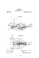
In the drawings illustrating the principle of my invention and the best mode now known to me of applying that principle, Figure 1 isaside elevation, partly in section, of so much of a dumping wagon as is necessary to illustrate my invention; and Fig. 2 is a bot-tom view of the same.
From the axle a extend forwardly the hounds b which carry a stationary shaft c. The rear end of the pole d is provided with the fork members e. Through the latter extends the stationary shaft c, so that the latter forms a pivotal connection between the pole al and the hounds Z). To the front face of the axle a are bolted the brackets f, in each of which is pivotally mounted a swinging arm g. To the bottom face of the pole d is rigidly fastened a bracket It having arms c' through the rear ends of which passes the stationary shaft c and each of which is formed with holes The front end of each swinging arm g is connected by a link 7c with the arm z' which lies on the same side of the pole with it. The holes y' permit an adjustment to be made of the position of the front end of the link 7c. A
Specicaton of Letters Patent.
Application filed June 7, 1909.
Patented Aug. 23, 1910.
Serial No. 500,567.
cross-pin m extends between the front ends of the swinging arms g and serves to support the rear ends of the link la. To this cross-pin m is hooked the rear end of a coil-springl n the front end of which is hooked to a cross-pin 0 which extends between the arms z' at the front part of the bracket it.
During the first part of the dumping movement of the wagon-body, the hounds are carried upwardly with the front endv of the latter, to which they are rigidly secured through the axle a, the latter serving as an axis of rotation; and during this first part of the dumping movement, the coil-sprlng at is stretched and the tension of the latter is exerted to maintain the parts in their normal position; that is, the first part of the dumping movement takes place against the tension of the coil-spring n. As the dumping movement progresses, the points of connection of the front ends of the links lc with the bracket-arms z' are raised above the line joining the points o, m in Fig. 1 or the plane passing through t-he cross-pins 0, m, and the coil-spring a now contracts; that is, as I term it, the coil-spring n passes center. During vthe first part of the return movement of the wagon-body, the coil-spring n is stretched and during the latter part of the return movement, the coilspring contracts.
I claim:
In a structure of the character described, the combination of a tongue; an axle; hounds connecting said tongue and axle; arms mounted free to swing on said axle; links pivotally connected with said arms; mechanism which is fastened to said tongue and which connects said links to said hounds; and a spring which is attached at one end to said tongue and at its other end is attached to said arms and links.
In testimony whereof I have hereunto set my hand at said Hoopeston, this 2d day of June, A. D., 1909, in the presence of the two undersigned witnesses.
PHILIP I-I. WEBBER.
Witnesses:
JOHN B. WALLBRIDGE, CECIL YOUNG. A
Priority Applications (1)
| Application Number | Priority Date | Filing Date | Title |
|---|---|---|---|
| US50056709A US968010A (en) | 1909-06-07 | 1909-06-07 | Tongue-support. |
Applications Claiming Priority (1)
| Application Number | Priority Date | Filing Date | Title |
|---|---|---|---|
| US50056709A US968010A (en) | 1909-06-07 | 1909-06-07 | Tongue-support. |
Publications (1)
| Publication Number | Publication Date |
|---|---|
| US968010A true US968010A (en) | 1910-08-23 |
Family
ID=3036401
Family Applications (1)
| Application Number | Title | Priority Date | Filing Date |
|---|---|---|---|
| US50056709A Expired - Lifetime US968010A (en) | 1909-06-07 | 1909-06-07 | Tongue-support. |
Country Status (1)
| Country | Link |
|---|---|
| US (1) | US968010A (en) |
-
1909
- 1909-06-07 US US50056709A patent/US968010A/en not_active Expired - Lifetime
Similar Documents
| Publication | Publication Date | Title |
|---|---|---|
| US208390A (en) | Improvement in carriage-springs | |
| US968010A (en) | Tongue-support. | |
| US443592A (en) | Road-cart | |
| US719535A (en) | Dumping-wagon. | |
| US1234014A (en) | Front-wheel mounting and steering attachment. | |
| US1351968A (en) | Antijounce-spring construction | |
| US550885A (en) | Sulky | |
| US269633A (en) | Torsion-spring for vehicles | |
| US854967A (en) | Draft device for wagons. | |
| US618271A (en) | Edwin jarrell | |
| US343134A (en) | William h | |
| US1120286A (en) | Motor-vehicle. | |
| US1131254A (en) | Child's and toy wagon. | |
| US660327A (en) | Running-gear for vehicles. | |
| US304567A (en) | schelp | |
| US635763A (en) | Body-loop for vehicles. | |
| US660608A (en) | Low-down short-turn gear for vehicles. | |
| US148118A (en) | Improvement in running-gears | |
| US204843A (en) | Improvement in jointed braces for vehicle-springs | |
| US1048608A (en) | Road-engine. | |
| US305998A (en) | Vehicle running-gear | |
| US1171658A (en) | Antiskid device for automobiles. | |
| US991019A (en) | Tongue-truck. | |
| US394751A (en) | Jedutheun p | |
| US1039526A (en) | Automatic cushion tongue-support. |