US9674828B2 - Terminal apparatus - Google Patents
Terminal apparatus Download PDFInfo
- Publication number
- US9674828B2 US9674828B2 US14/646,462 US201314646462A US9674828B2 US 9674828 B2 US9674828 B2 US 9674828B2 US 201314646462 A US201314646462 A US 201314646462A US 9674828 B2 US9674828 B2 US 9674828B2
- Authority
- US
- United States
- Prior art keywords
- base station
- station apparatus
- unit
- information
- terminal apparatus
- Prior art date
- Legal status (The legal status is an assumption and is not a legal conclusion. Google has not performed a legal analysis and makes no representation as to the accuracy of the status listed.)
- Active
Links
Images


Classifications
-
- H04W72/042—
-
- H—ELECTRICITY
- H04—ELECTRIC COMMUNICATION TECHNIQUE
- H04W—WIRELESS COMMUNICATION NETWORKS
- H04W28/00—Network traffic management; Network resource management
- H04W28/16—Central resource management; Negotiation of resources or communication parameters, e.g. negotiating bandwidth or QoS [Quality of Service]
- H04W28/18—Negotiating wireless communication parameters
-
- H—ELECTRICITY
- H04—ELECTRIC COMMUNICATION TECHNIQUE
- H04W—WIRELESS COMMUNICATION NETWORKS
- H04W16/00—Network planning, e.g. coverage or traffic planning tools; Network deployment, e.g. resource partitioning or cells structures
- H04W16/24—Cell structures
- H04W16/32—Hierarchical cell structures
-
- H—ELECTRICITY
- H04—ELECTRIC COMMUNICATION TECHNIQUE
- H04L—TRANSMISSION OF DIGITAL INFORMATION, e.g. TELEGRAPHIC COMMUNICATION
- H04L5/00—Arrangements affording multiple use of the transmission path
- H04L5/0001—Arrangements for dividing the transmission path
- H04L5/0014—Three-dimensional division
- H04L5/0023—Time-frequency-space
-
- H—ELECTRICITY
- H04—ELECTRIC COMMUNICATION TECHNIQUE
- H04L—TRANSMISSION OF DIGITAL INFORMATION, e.g. TELEGRAPHIC COMMUNICATION
- H04L5/00—Arrangements affording multiple use of the transmission path
- H04L5/003—Arrangements for allocating sub-channels of the transmission path
- H04L5/0042—Arrangements for allocating sub-channels of the transmission path intra-user or intra-terminal allocation
-
- H—ELECTRICITY
- H04—ELECTRIC COMMUNICATION TECHNIQUE
- H04W—WIRELESS COMMUNICATION NETWORKS
- H04W52/00—Power management, e.g. TPC [Transmission Power Control], power saving or power classes
- H04W52/04—TPC
- H04W52/06—TPC algorithms
- H04W52/14—Separate analysis of uplink or downlink
- H04W52/146—Uplink power control
-
- H—ELECTRICITY
- H04—ELECTRIC COMMUNICATION TECHNIQUE
- H04W—WIRELESS COMMUNICATION NETWORKS
- H04W52/00—Power management, e.g. TPC [Transmission Power Control], power saving or power classes
- H04W52/04—TPC
- H04W52/38—TPC being performed in particular situations
- H04W52/40—TPC being performed in particular situations during macro-diversity or soft handoff
-
- H—ELECTRICITY
- H04—ELECTRIC COMMUNICATION TECHNIQUE
- H04W—WIRELESS COMMUNICATION NETWORKS
- H04W52/00—Power management, e.g. TPC [Transmission Power Control], power saving or power classes
- H04W52/04—TPC
- H04W52/54—Signalisation aspects of the TPC commands, e.g. frame structure
- H04W52/58—Format of the TPC bits
-
- H—ELECTRICITY
- H04—ELECTRIC COMMUNICATION TECHNIQUE
- H04W—WIRELESS COMMUNICATION NETWORKS
- H04W72/00—Local resource management
- H04W72/20—Control channels or signalling for resource management
-
- H—ELECTRICITY
- H04—ELECTRIC COMMUNICATION TECHNIQUE
- H04W—WIRELESS COMMUNICATION NETWORKS
- H04W72/00—Local resource management
- H04W72/20—Control channels or signalling for resource management
- H04W72/23—Control channels or signalling for resource management in the downlink direction of a wireless link, i.e. towards a terminal
-
- H—ELECTRICITY
- H04—ELECTRIC COMMUNICATION TECHNIQUE
- H04L—TRANSMISSION OF DIGITAL INFORMATION, e.g. TELEGRAPHIC COMMUNICATION
- H04L5/00—Arrangements affording multiple use of the transmission path
- H04L5/0001—Arrangements for dividing the transmission path
- H04L5/0003—Two-dimensional division
- H04L5/0005—Time-frequency
- H04L5/0007—Time-frequency the frequencies being orthogonal, e.g. OFDM(A), DMT
- H04L5/001—Time-frequency the frequencies being orthogonal, e.g. OFDM(A), DMT the frequencies being arranged in component carriers
-
- H—ELECTRICITY
- H04—ELECTRIC COMMUNICATION TECHNIQUE
- H04L—TRANSMISSION OF DIGITAL INFORMATION, e.g. TELEGRAPHIC COMMUNICATION
- H04L5/00—Arrangements affording multiple use of the transmission path
- H04L5/003—Arrangements for allocating sub-channels of the transmission path
- H04L5/0048—Allocation of pilot signals, i.e. of signals known to the receiver
- H04L5/0051—Allocation of pilot signals, i.e. of signals known to the receiver of dedicated pilots, i.e. pilots destined for a single user or terminal
-
- H—ELECTRICITY
- H04—ELECTRIC COMMUNICATION TECHNIQUE
- H04W—WIRELESS COMMUNICATION NETWORKS
- H04W52/00—Power management, e.g. TPC [Transmission Power Control], power saving or power classes
- H04W52/04—TPC
- H04W52/30—TPC using constraints in the total amount of available transmission power
- H04W52/36—TPC using constraints in the total amount of available transmission power with a discrete range or set of values, e.g. step size, ramping or offsets
- H04W52/367—Power values between minimum and maximum limits, e.g. dynamic range
-
- H—ELECTRICITY
- H04—ELECTRIC COMMUNICATION TECHNIQUE
- H04W—WIRELESS COMMUNICATION NETWORKS
- H04W88/00—Devices specially adapted for wireless communication networks, e.g. terminals, base stations or access point devices
- H04W88/02—Terminal devices
Definitions
- the present invention relates to a terminal apparatus.
- NPL 1 it has been considered in NPL 1 etc., that in addition to a conventional cellular system in which a cell is formed so that each of macro base stations with the same scale covers different communication areas, by newly arranging a pico base station having a communication area smaller than that of the macro base station in a cell to form a new cell, it is sought to subdivide a′ communication area per base station to increase communication capacity (hereinafter, a cell formed by the macro base station is referred to as a macro cell, and a cell formed by the pico base station is referred to as a small cell).
- a cell formed by the macro base station is referred to as a macro cell
- a cell formed by the pico base station is referred to as a small cell.
- the macro base station instructs a terminal apparatus which is positioned in the small cell to connect with the pico base station.
- a load imposed on the macro base station is able to be offloaded to the pico base station, resulting that transmission opportunities of all terminal apparatuses in the macro cell are able to be increased.
- a transmission scheme of a transmit signal is desired to have a PAPR (Peak to Average Power Ratio) as low as possible in order to seek linear amplification with high efficiency.
- PAPR Peak to Average Power Ratio
- DFT-S-OFDM Discrete Fourier Transform Spread Orthogonal Frequency Division Multiplexing; also referred to as SC-FDMA (Single Carrier Frequency Division Multiple Access)
- SC-FDMA Single Carrier Frequency Division Multiple Access
- NPL 1 NTT DOCOMO, “Enhanced Cell Identification for Additional Carrier Type”, 3GPP, 3GPP TSG RAN WG1 Meeting #68 R1-120398
- the terminal apparatus has remaining transmit power because the cell is small, and there is a problem that excellent transmission efficiency is not able to be achieved if the terminal apparatus is controlled in the same manner as the macro cell.
- the present invention has been made in view of such circumstances, and an object thereof is to provide a terminal apparatus which achieves excellent transmission efficiency in a mobile communication system in which a small cell is arranged in a macro cell.
- an aspect of the present invention is a terminal apparatus capable of transmitting a signal to a first communication apparatus and a second communication apparatus, including: a reception unit that receives information associated with the first communication apparatus or the second communication apparatus from the first communication apparatus; a control unit that switches a maximum number of clusters used for transmission of the signal based on the information; and a transmission unit that transmits the signal by using the maximum number of clusters, which is switched by the control unit, in which the control unit uses different maximum numbers of clusters between a case where the signal is transmitted to the first communication apparatus based on the information and a case where the signal is transmitted to the second communication apparatus based on the information.
- another aspect of the present invention is a first communication apparatus capable of transmitting a signal to a terminal apparatus, including a transmission unit that transmits, to the terminal apparatus, information used for determining to which of the first communication apparatus and a second communication apparatus that is different from the first communication apparatus the signal is to be transmitted by the terminal apparatus.
- another aspect of the present invention is a communication method in a terminal apparatus capable of transmitting a signal to a first communication apparatus and a second communication apparatus, including: a first step of receiving information associated with the first communication apparatus or the second communication apparatus from the first communication apparatus; a second step of switching a maximum number of clusters used for transmission of the signal based on the information; and a third step of transmitting the signal by using the maximum number of clusters, which is switched in the second step, in which the second step uses different maximum numbers of clusters between a case where the signal is transmitted to the first communication apparatus based on the information and a case where the signal is transmitted to the second communication apparatus based on the information.
- another aspect of the present invention is a communication method in a first communication apparatus capable of transmitting a signal to a terminal apparatus, including a step of transmitting, to the terminal apparatus, information used for determining to which of the first communication apparatus and a second communication apparatus that is different from the first communication apparatus the signal is to be transmitted by the terminal apparatus.
- FIG. 1 is a conceptual diagram showing a configuration of a radio communication system according to a first embodiment of the present invention
- FIG. 2 is a schematic block diagram showing a configuration of a terminal apparatus 20 according to the same embodiment
- FIG. 3 is a schematic block diagram showing a configuration of a control unit 214 according to the same embodiment
- FIG. 4 is a conceptual diagram explaining Clustered DFT-S-OFDM which is a communication scheme used in the case of transmission by the terminal apparatus 20 according to the same embodiment;
- FIG. 5 is a view showing an example of assignment information which is generated by a macro base station apparatus 30 a according to the same embodiment
- FIG. 6 is a view showing an example of assignment information which is generated by a pico base station apparatus 30 b according to the same embodiment
- FIG. 7 is a view showing association of a time interval and a frequency interval which are stored in an interval storage unit for macro 236 with an index according to the same embodiment
- FIG. 8 is a view showing association of a time interval and a frequency interval which are stored in an interval storage unit for pico 237 with an index according to the same embodiment
- FIG. 9 is a view showing another example of association of a time interval and a frequency interval which are stored in the interval storage unit for pico 237 with an index according to the same embodiment
- FIG. 10 is a schematic block diagram showing a configuration of the macro base station apparatus 30 a according to the same embodiment
- FIG. 11 is a schematic block diagram showing a configuration of the pico base station apparatus 30 b according to the same embodiment
- FIG. 12 is a schematic block diagram showing a configuration of a control unit 214 A of a terminal apparatus 21 according to a second embodiment of the present invention.
- FIG. 13 is a view showing an example of a storage content of an RBG size storage unit for macro 240 a according to the same embodiment
- FIG. 14 is a view showing an example of a storage content of an RBG size storage unit for pico 240 b according to the same embodiment
- FIG. 15 is a schematic block diagram showing a configuration of a control unit 214 B of a terminal apparatus 22 according to a third embodiment of the present invention.
- FIG. 16 is a view showing an example of a storage content of an MCS storage unit for macro 241 a according to the same embodiment
- FIG. 17 is a view showing an example of a storage content of an MCS storage unit for pico 241 b according to the same embodiment
- FIG. 18 is a view showing another example of a storage content of the MCS storage unit for pico 241 b according to the same embodiment
- FIG. 19 is a schematic block diagram showing a configuration of a control unit 214 C of a terminal apparatus 23 according to the third embodiment of the present invention.
- FIG. 20 is a view showing an example of a storage content of a pattern storage unit for macro 242 a according to the same embodiment.
- FIG. 21 is a view showing an example of a storage content of a pattern storage unit for pico 242 b according to the same embodiment.
- a terminal apparatus discriminates the macro base station and the pico base station according to a measure of maximum transmit power of the downlink in each embodiment. From each of the base stations, information associated with maximum transmit power of the base stations may be notified to the terminal apparatus in the downlink, or from the macro base station, information associated with maximum transmit power of its own station and the pico base station may be notified to the terminal apparatus. Other identification methods are of course not excluded from the present invention.
- FIG. 1 is a conceptual diagram showing a configuration of a radio communication system according to a first embodiment of the present invention.
- a radio communication system 10 according to the present embodiment is configured by including a macro base station apparatus 30 a , a pico base station apparatus 30 b , and a terminal apparatus 20 .
- the numbers of the respective base station apparatuses and the terminal apparatuses are one example, and any of them may be included in a plurality of pieces or each of them may be included in a plurality of pieces.
- the macro base station apparatus 30 a is a base station apparatus which performs radio communication with the terminal apparatus 20 .
- the pico base station apparatus 30 b is also a base station apparatus which performs radio communication with the terminal apparatus 20 , but, if being compared to the macro base station apparatus 30 a , is different in terms of having smaller maximum transmit power and a narrower communication range.
- FIG. 2 is a schematic block diagram showing a configuration of the terminal apparatus 20 according to the present embodiment.
- description will be given by taking a configuration of a case where the maximum number of transmission streams that is usable by the terminal apparatus is two, as an example. Note that, a number of a part to which a number is assigned with hyphen in FIG. 2 (part assigned with hyphen 2 in FIG. 2 ) is determined by the maximum number of transmission streams that is usable by the terminal apparatus.
- the terminal apparatus 20 is configured by including coding units 201 - 1 and 201 - 2 , S/P (Serial/Parallel) conversion units 202 - 1 and 202 - 2 , DFT (Discrete Fourier Transform) units 203 - 1 and 203 - 2 , power control units 204 - 1 and 204 - 2 , RB assignment units 205 - 1 and 205 - 2 , a precoating unit 206 , SRS multiplex units 207 - 1 and 207 - 2 , IDFT (Inverse Discrete Fourier Transform) units 208 - 1 and 208 - 2 , CP (Cyclic Prefix) insertion units 209 - 1 and 209 - 2 , P/S (Parallel/Serial) conversion units 210 - 1 and 210 - 2 , D/A (Digital/Analog) conversion units 211 - 1 and 211 - 2 , RF (Radio Frequency) units 212
- the coding unit 201 - 1 performs error correction coding of a bit sequence of a first stream, and then performs modulation such as BPSK (Binary Phase Shift Keying), QPSK (Quaternary Phase Shift Keying), or 16QAM (16-ary guadrature amplitude modulation) to generate a symbol string.
- the coding unit 201 - 2 performs same processing for a bit sequence of a second stream. Note that, both the coding units 201 - 1 and 201 - 2 follow designation from the control unit 214 as to a coding rate at the time of the error correction coding and the modulation scheme at the time of the modulation.
- the S/P conversion unit 202 - 1 performs serial/parallel conversion for the symbol string generated by the coding unit 201 - 1 . Note that, a parallel number of a serial/parallel conversion result is matched with a DFT point number in the DFT unit 203 - 1 .
- the S/P conversion unit 202 - 2 performs same processing for a symbol string generated by the coding unit 201 - 2 .
- the DFT unit 203 - 1 performs discrete Fourier transform for the conversion result by the S/P conversion unit 202 - 1 to generate a discrete spectrum.
- the DFT unit 203 - 2 performs same processing for a conversion result by the S/P conversion unit 202 - 2 .
- the power control unit 204 - 1 multiplies the discrete spectrum generated by the DFT unit 203 - 1 by a coefficient designated from the control unit 214 .
- the power control unit 204 - 2 multiplies a discrete spectrum generated by the DFT unit 203 - 2 by a coefficient designated from the control unit 214 .
- the RB assignment unit 205 - 1 arranges the discrete spectrum which is multiplied by the coefficient at the power control unit 204 - 1 in a resource block designated from the control unit 214 and generates a frequency signal of the first stream.
- the RB assignment unit 205 - 2 performs same processing for the discrete spectrum which is multiplied by the coefficient at the power control unit 204 - 2 and generates a frequency signal of the second stream.
- the resource block is configured by one or more contiguous subcarriers and a continuous time width for a one symbol time or more, and is a minimum assignment unit in the event that the macro base station apparatus 30 a and the pico base station apparatus 30 b assign a radio resource to the terminal apparatus 20 .
- the precoding unit 206 multiplies a precoding matrix designated from the control unit 214 by vector composed of the frequency signal of the first stream and the frequency signal of the second stream and calculates the frequency signal for each of the transmit antenna units 213 - 1 and 213 - 2 . Note that, in the case where the number of streams is one, the precoding matrix designated from the control unit 214 is multiplied by the frequency signal of the first stream and the frequency signal for each of the transmit antenna units 213 - 1 and 213 - 2 is calculated.
- the SRS multiplex unit 207 - 1 multiplexes the frequency signal for the transmit antenna unit 213 - 1 , which is generated by the precoding unit 206 , with a sounding reference signal.
- the SRS multiplex unit 207 - 2 multiplexes the frequency signal for the transmit antenna unit 213 - 2 with the sounding reference signal in the same manner.
- the IDFT unit 208 - 1 performs inverse Fourier transform for the frequency signal which is multiplexed with the sounding reference signal by the SRS multiplex unit 207 - 1 and generates a time signal for the transmit antenna unit 213 - 1 .
- the IDFT unit 208 - 2 performs the same for the frequency signal which is multiplexed with the sounding reference signal by the SRS multiplex unit 207 - 2 and generates a time signal for the transmit antenna unit 213 - 2 .
- a DFT point number in the event of performing the inverse Fourier transform is a point number according to a system bandwidth.
- the sounding reference signal is a signal for grasping a state of a channel. The state of the channel, which is grasped with the signal, is used in the event of determining the radio resource to be assigned to the terminal apparatus 20 , etc.
- the CP insertion unit 209 - 1 inserts a cyclic prefix to the time signal generated by the IDFT unit 208 - 1 .
- a signal of a predetermined point number from an end of a symbol zone in the time signal generated by the IDFT unit 208 - 1 is copied to be inserted at a head of the symbol zone.
- the parallel number of the time signal input to the CP insertion unit 209 - 1 is the point number according to the system bandwidth
- the parallel number of the signal in which the cyclic prefix is inserted by the CP insertion unit 209 - 1 is a number obtained by adding the point number for copying to the point number according to the system bandwidth.
- the CP insertion unit 209 - 2 performs processing in the same manner for the time signal generated by the IDFT unit 208 - 2 .
- the P/S conversion unit 210 - 1 performs parallel/serial conversion for the signal in which the cyclic prefix is inserted by the CP insertion unit 209 - 1 to generate a serial signal.
- the P/S conversion unit 210 - 2 performs same processing for the signal in which the cyclic prefix is inserted by the CP insertion unit 209 - 2 .
- the D/A conversion unit 211 - 1 performs digital/analog conversion of the serial signal generated by the P/S conversion unit 210 - 1 to generate an analog signal.
- the D/A conversion unit 211 - 2 performs same processing for a serial signal generated by the P/S conversion unit 210 - 2 .
- the RF unit 212 - 1 up-converts the analog signal generated by the D/A conversion unit 211 - 1 to a radio frequency, which is subjected to radio transmission from the transmit antenna unit 213 - 1 .
- the RF unit 212 - 2 up-converts the analog signal generated by the D/A conversion unit 211 - 2 to a radio frequency, which is subjected to radio transmission from the transmit antenna unit 213 - 2 .
- the receive antenna unit 220 receives signals transmitted by the macro base station apparatus 30 a and the pico base station apparatus 30 b .
- the reception unit 221 detects control information CI from the signals received by the receive antenna unit 220 to input to the control unit 214 .
- This control information CI includes power control information associated with transmit power control, resource block assignment information, MCS (Modulation and Coding Scheme) information for designating a coding rate and a modulation scheme, rank information for designating the number of streams, precoding information for designating a precoding matrix, and SRS information for designating arrangement of the sounding reference signal.
- MCS Modulation and Coding Scheme
- the control unit 214 designates the coding rate and the modulation scheme to the coding units 201 - 1 and 201 - 2 based on the control information CI input from the reception unit 221 . In the same manner, the control unit 214 designates the coefficient to be multiplied by the frequency signal for controlling power to the power control units 205 - 1 and 205 - 2 . Further, the control unit 214 designates the resource block in which the signal is arranged to the RB assignment units 205 - 1 and 205 - 2 based on the input control information CI. Note that, in the present embodiment, the macro base station apparatus 30 a and the pico base station apparatus 30 b have different formats of the assignment information which is included in the control information CI and is for designating assignment of the resource block.
- control unit 214 designates the precoating matrix which is used to the precoating unit 206 based on the input control information CI. Further, the control unit 214 designates arrangement of the sounding reference signal SA to the SRS generation unit 215 based on the input control information CI. In addition, the control unit 214 judges the number of streams based on the input control information CI, and in the case where the number of streams is one, causes only a portion which performs processing associated with the first stream to operate, and does not cause a portion which performs processing associated with the second stream to operate. Moreover, in the case where the number of streams is two as a result of the judgment, both of the portion which performs processing associated with the first stream and the portion which performs processing associated with the second stream are caused to operate.
- the portion which performs processing associated with the first stream includes the coding unit 201 - 1 , the S/P conversion unit 202 - 1 , the DFT unit 203 - 1 , the power control unit 204 - 1 and the RB assignment unit 205 - 1 .
- the portion which performs processing associated with the second stream includes the coding unit 201 - 2 , the S/P conversion unit 202 - 2 , the DFT unit 203 - 2 , the power control unit 204 - 2 and the RB assignment unit 205 - 2 .
- the SRS generation unit 215 generates the sounding reference signal to be transmitted from the transmit antenna unit 213 - 1 in accordance with the designation of the arrangement SA from the control unit 214 to input to the SRS multiplex unit 207 - 1 . In the same manner, the SRS generation unit 215 generates the sounding reference signal to be transmitted from the transmit antenna unit 213 - 2 to input to the RS multiplex unit 207 - 2 .
- FIG. 3 is a schematic block diagram showing a configuration of the control unit 214 .
- the control unit 214 is configured by including an assignment information extraction unit 230 , an assignment RB judgment unit 231 , a base station type judgment unit 232 , a power control unit information extraction unit 233 , a coefficient calculation unit 234 , an SRS schedule determination unit 235 , an interval storage unit for macro 236 , an interval storage unit for pico 237 , a precoding determination unit 238 and an MCS determination unit 239 .
- the assignment information extraction unit 230 extracts assignment information from the control information CI input from the reception unit 221 .
- the assignment information extraction unit 230 changes a format of the assignment information to be extracted according to a type of a destination base station acquired from the base station type judgment unit 232 .
- the format of the assignment information to be extracted in the case where the type of the destination base station is the pico base station is a format which has a smaller bit number than the format of the assignment information to be extracted in the case where the type of the destination base station is the macro base station.
- the assignment information extraction unit 230 extracts the assignment information with a maximum value of the number of clusters of “3” from the control information CI.
- the assignment information extraction unit 230 extracts the assignment information with the maximum value of the number of clusters of “2” from the control information CI. That is, the pico base station as the type of the destination base station has the smaller maximum value of the number of clusters than the macro base station and thus has the format with less bit number.
- the assignment RB judgment unit 231 notifies the RB assignment units 205 - 1 and 205 - 2 of designation of the resource block in which the signal is arranged based on the assignment information extracted by the assignment information extraction unit 230 .
- the base station type judgment unit 232 judges the type of the destination base station based on information associated with maximum transmit power of the destination base station, which is notified as the power control information, and notifies the assignment information extraction unit 230 and the SRS schedule determination unit 235 of a judgment result.
- the types of the base station includes the macro base station and the pico base station.
- the base station type judgment unit 232 judges as the macro base station if the maximum transmit power exceeds a predetermined threshold and judges as the pico base station if not exceeding.
- one notified by the destination base station as system information may be used as the information associated with the maximum transmit power.
- the destination base station may notify information showing a type of its own station as the system information so that the base station type judgment unit 232 judges the type of the destination base station based on the information.
- the power control information extraction unit 233 extracts power control information from the control information CI.
- the power control information extraction unit 233 notifies the base station type judgment unit 232 of information showing the maximum transmit power of the destination base station of the power control information. Further, the power control information extraction unit 233 notifies the coefficient calculation unit 234 of information for designating transmit power of the terminal apparatus 20 of the power control information.
- the coefficient calculation unit 234 calculates the coefficient to be multiplied by the frequency signal so as to provide designated transmit power.
- the information for designating the transmit power may be information for designating a difference from previous transmit power. In this case, the coefficient calculation unit 234 sets a value obtained by changing a previous coefficient based on the difference designated by the information as the coefficient to be multiplied by the frequency signal.
- the SRS schedule determination unit 235 extracts SRS information from the control information CI, and determines arrangement of the sounding reference signal based on the SRS information.
- the SRS schedule determination unit 235 refers to the interval storage unit for macro 236 in the event of determining arrangement of the sounding reference signal.
- the SRS schedule determination unit 235 refers to the interval storage unit for pico 237 in the event of determining arrangement of the sounding reference signal.
- the SRS schedule determination unit 235 reads a time interval and a frequency interval according to an index indicated by the SRS information from the interval storage unit for macro 236 or the interval storage unit for pico 237 , and determines arrangement of the sounding reference signal in accordance with the time interval and the frequency interval which are read.
- the time interval is a cycle in which the sounding reference signal is arranged in an entire system band
- the frequency interval is a subcarrier interval at which the sounding reference signal is arranged.
- the time interval and the frequency interval by taking a case where the system band has an RB number 0 to the RB number 127 as an example.
- the sounding reference signal is arranged in resource blocks of the RB number 0 to the RB number 63 in a slot 0 (slot is a time zone which is defined by one or more continuous symbol time) and arranged in resource blocks of the RB number 64 to the RB number 127 in a slot 11 , the sounding reference signal is to be arranged in the entire system band.
- time from the slot 0 to the slot 50 serves as the time interval.
- the sounding reference signal is not arranged in all subcarriers but, for example, for every four subcarriers, these four subcarriers are the frequency time interval.
- the interval storage unit for macro 236 stores the time interval and the frequency interval at which the sounding reference signal is arranged in association with the index.
- the interval storage unit for macro 236 is referred to in the case where the destination base station is the macro base station.
- the interval storage unit for pico 237 stores the time interval and the frequency interval at which the sounding reference signal is arranged in association with the index.
- the interval storage unit for pico 237 is referred to in the case where the destination base station is the pico base station.
- a minimum value of the time interval or the frequency interval stored in the interval storage unit for pico 237 is larger than a minimum value of the time interval or the frequency interval stored in the interval storage unit for macro 236 .
- the interval storage unit for macro 236 and the interval storage unit for pico 237 may store not the time interval and the frequency interval, but information representing arrangement of the sounding reference signal.
- the SRS schedule determination unit 235 uses arrangement of the sounding reference signal which is represented by information associated with the index indicated by the SRS information.
- a minimum value of the time interval or the frequency interval of arrangement which is represented by the information stored in the interval storage unit for pico 237 is larger than a minimum value of the time interval or the frequency interval of arrangement which is represented by the information stored in the interval storage unit for macro 236 .
- the precoding determination unit 238 extracts an index indicating a combination of the number of streams and the precoding matrix from the control information CI.
- the precoding determination unit 238 determines the number of streams and the precoding matrix to be used based on the extracted index to notify the precoding unit 206 .
- the MCS determination unit 239 extracts MCS information from the control information CI.
- the MCS determination unit 239 notifies the coding unit 201 of the modulation scheme and the coding rate which are indicated by the extracted MCS information.
- FIG. 4 is a conceptual diagram explaining Clustered DFT-S-OFDM which is a communication scheme used in the case of transmission by the terminal apparatus 20 .
- an horizontal axis is a frequency
- each frequency band assigned with reference numerals RB 0 , RB 1 , RB 2 , RB 5 , RB 6 , RB 8 and RB 9 is a resource block assigned to the terminal apparatus 20 .
- all contiguous frequency bands are assigned in the DFT-S-OFDM
- some contiguous frequency bands are assigned discretely in the Clustered DFT-S-OFDM.
- Respective some contiguous frequency bands which are assigned discretely are referred to as a cluster.
- FIG. 4 an horizontal axis is a frequency
- each frequency band assigned with reference numerals RB 0 , RB 1 , RB 2 , RB 5 , RB 6 , RB 8 and RB 9 is a resource block assigned to the terminal apparatus 20 .
- the resource blocks RB 0 , RB 1 and RB 2 are contiguous frequency bands and constitute a cluster C 11 .
- the resource blocks RB 5 and RB 6 are contiguous frequency bands and constitute a cluster C 12 .
- the resource blocks RB 8 and RB 9 are contiguous frequency bands and constitute a cluster C 13 . That is, the number of clusters is three in the example shown in FIG. 4 . Note that, a maximum value of the number of clusters is also referred to as a maximum division number.
- the Clustered DFT-S-OFDM is able to use discrete frequency resources, and thus has advantages that a frequency selection diversity gain by selection of resource blocks to be used is able to be expected and band use efficiency is improved by flexible selection of resource blocks, but has an disadvantage that PAPR (Peak to Average Power Ratio) performances are deteriorated by using the discrete resource blocks.
- PAPR Peak to Average Power Ratio
- FIG. 5 is a view showing an example of assignment information which is generated by the macro base station apparatus 30 a .
- a format of assignment information generated by the macro base station apparatus 30 a is a format having the maximum value of the number of clusters (maximum division number) of “3”.
- the example of the assignment information shown in FIG. 5 is composed of the RB number “0” and the number of RBs “3” of the cluster C 11 , the RB number “5” and the number of RBs “2” of the cluster C 12 , and the RB number “8” and the number of RBs “2” of a cluster C 13 . That is, the format has each three (maximum value of the number of clusters) of regions in which the RB number is arranged and regions in which the number of RBs is arranged.
- the RB number is a serial number beginning from 0 which is assigned to each resource block in order from a smaller frequency.
- the number of RBs is the number of contiguous resource blocks constituting the cluster. For example, in the assignment information shown in FIG. 5 , since the RB number and the number of RBs of the cluster C 13 are “8” and “2”, the cluster C 13 is composed of resource blocks having the RB numbers of “8” and “9”.
- FIG. 6 is a view showing an example of assignment information which is generated by the pico base station apparatus 30 b .
- a format of assignment information generated by the pico base station apparatus 30 b is a format having the maximum value of the number of clusters of “2” which is a smaller value than the case of the macro base station apparatus 30 a .
- the example of the assignment information shown in FIG. 5 is composed of the RB number “13 and the number of RBs “12” of a cluster C 11 , and the RB number “29” and the number of RBs “6” of a cluster C 12 . That is, the format has each two (maximum value of the number of clusters) of regions in which the RB number is arranged and regions in which the number of RBs is arranged.
- a bit number which is necessary for designating the RB number is a
- a bit number which is necessary for designating the number of RBs is b
- the bit number of N (a+b) becomes necessary for the assignment information.
- the bit number which is necessary for the assignment information of the pico base station apparatus 30 b is (N ⁇ c) ⁇ (a+b).
- the assignment information of the pico base station apparatus 30 b is able to achieve reduction of c (a+b) bits compared to the assignment information of the macro base station apparatus 30 a .
- c is “1”.
- the format of assignment information other format may be used.
- bit information showing a combination of the RB number of a head and the RB number of termination in each cluster may be used.
- the maximum value of the number of clusters in the pico base station apparatus 30 b may be “1” and the terminal apparatus 20 may perform transmission to the pico base station apparatus 30 b by using not the Clustered DFT-S-OFDM but the DFT-S-OFDM.
- the advantage of the assignment by dividing into a plurality of clusters is to acquire a diversity gain by selecting resource blocks with excellent channel performances.
- flexibility of the assignment of resource blocks is enhanced, so that it is possible to further improve the diversity gain by assigning resource blocks with more excellent channel performances.
- the small cell which is a service area of the pico base station apparatus 30 b has a narrow cell range, distance attenuation between the pico base station apparatus 30 b and the terminal apparatus 20 is suppressed.
- the small cell has a narrow cell range and is therefore not susceptible to a delay wave compared to the macro cell, so that frequency selectivity of a channel is relatively weak. In such an environment, the frequency diversity gain by assigning resource blocks discretely is reduced.
- the formula (1) is for a case where only the PUSCH is transmitted with the macro base station apparatus 30 a or the pico base station apparatus 30 b as a reception station in the uplink.
- P PUSCH ( i ) min ⁇ P CMAX ( i ),10log 10 (M PUSCH ( i ))+P 0 _ PUSCH ( j )+ ⁇ ( j ) ⁇ PL + ⁇ ( i )+ f ( i ) ⁇ (1)
- a function min is a function which returns a minimum element in an argument.
- P CMAX (i) is maximum transmit power which is able to be assigned by the terminal apparatus
- i is a sub-frame number for transmitting the PUSCH of a control target
- M PUSCH (i) is the number of resource blocks of the PUSCH.
- P 0 _ PUSCH (j) is for prescribing target receive power of the reception station (minimum power demanded in the reception station), and is determined by a sum of P 0 _ NOMINAL _ PUSCH (j) and P 0 _ UE _ PUSCH (j) notified from the reception station.
- PL is a value of channel loss (path loss) (which is also referred to as coupling loss and may be loss in consideration of an antenna gain or the like) with decibel (dB) as a unit estimated by the terminal apparatus 20 by using a reference signal which is transmitted in the downlink
- ⁇ (i) is a value determined by a modulation scheme or a coding scheme used by the terminal apparatus 20
- f(i) is a TPC command which is used for transmit power control by closed loop (a control value of transmit power transmitted from the reception station) and is notified from the reception station.
- the formula (1) is for calculating transmit power for satisfying a fixed reception level at the reception station in the event that the terminal apparatus 20 transmits the PUSCH, meaning that in the case where this transmit power is smaller than the maximum transmit power P CMAX (i) of the PUSCH, which is allowed in the terminal apparatus, the transmission is performed by using this transmit power, and in the case of being larger than P CMAX (i), the transmission is performed with P CMAX (i) as transmit power.
- the terminal apparatus 20 is able to achieve receive power desired by the reception station with small transmit power as the number of clusters increases.
- the pico base station apparatus 30 b instructs the terminal apparatus 20 to increase the transmit power for lacking power by notifying a TPC command which is used for transmit power control by the closed loop in the formula (1) over a plurality of times.
- the receive power desired by the pico base station apparatus 30 b is also able to be achieved.
- the transmit power in the event that the terminal apparatus 20 performs communication with the pico base station apparatus 30 b becomes larger than the transmit power in the event that the terminal apparatus 20 performs communication with the macro base station apparatus 30 a .
- a method for setting the target receive power of the pico base station apparatus 30 b to the target receive power of the macro base station apparatus 30 a or more is one of methods for setting a coefficient which is designated to the power control unit 204 - 1 and the power control unit 204 - 2 from the control unit 214 so that “the transmit power in the case where the terminal apparatus 20 performs communication with the pico base station apparatus 30 b >the transmit power in the case where the terminal apparatus 20 performs communication with the macro base station apparatus 30 a , in a case where the channel loss between the terminal apparatus 20 and the macro base station apparatus 30 a is the same as the channel loss between the terminal apparatus 20 and the pico base station apparatus 30 b”.
- control unit 214 may set ⁇ (i) to a larger value in the case of transmission to the pico base station apparatus 30 b than the case of transmission to the macro base station apparatus 30 a even in the case where the modulation schemes and the coding schemes are the same.
- a range of the present invention is not departed also in the case where other methods are used, including, for example, transmit power control in which transmit power is calculated such that in a case where the terminal apparatus 20 receives a TPC command from the pico base station apparatus 30 b , the terminal apparatus 20 translates a transmit power control value by the TPC command to a larger transmit power control value than a case where the TPC command is received from the macro base station apparatus 30 a (an example of translation of the TPC command is shown: in the case where the transmit power control value by the TPC command “00” is ⁇ 1 decibel, the transmit power control value by the TPC command “01” is 0 decibel, the transmit power control value by the TPC command “10” is 1 decibel and the transmit power control value by the TPC command “11” is 3 decibel, the terminal apparatus 20 translates the transmit power control value by the TPC command “00” to ⁇ 1 decibel, the transmit power control value by the TPC command “01” to 0 decibel, the transmit power control value
- the maximum value of the number of clusters at the time of connection with the pico base station apparatus 30 b is made smaller than the maximum value of the number of clusters at the time of connection with the macro base station apparatus 30 a , it is possible to reduce an information quantity of the control information without occurrence of degradation of communication quality.
- the terminal apparatus 20 may notify the macro base station apparatus 30 a and the pico base station apparatus 30 b of different values as to the maximum value of the number of clusters that is able to be transmitted by the terminal apparatus 20 so that the maximum value of the number of clusters becomes different between assignment information used by the macro base station apparatus 30 a and assignment information used by the pico base station apparatus 30 b .
- each of the terminal apparatuses 20 may notify only the macro base station apparatus 30 a of the maximum value of the number of clusters, and the macro base station apparatus 30 a may notify the pico base station apparatus 30 b by changing the maximum value notified from each of the terminal apparatuses 20 (by changing to the maximum value of the number of clusters that the pico base station is able to perform designation to the terminal apparatus 20 ).
- the terminal apparatus 20 notifies only the macro base station apparatus 30 a of the maximum value of the number of clusters, and if the macro base station apparatus 30 a notifies the pico base station apparatus 30 b by changing this maximum value, the terminal apparatus 20 notifies the macro base station apparatus 30 a of the maximum value as 3 and the macro base station apparatus 30 a notifies the pico base station apparatus 30 b of the maximum value of this terminal apparatus 20 as 2 .
- overhead associated with notification is increased compared to the case where communication only with the macro base station apparatus 30 a is premised.
- the number of clusters in communication of the terminal apparatus 20 with the pico base station apparatus 30 b may be set to be only a predetermined value. This makes is possible to reduce the overhead associated with notification described above. Note that, as shown before, since it is considered that there is a margin in transmit power in the communication of the terminal apparatus 20 with the pico base station apparatus 30 b and there is less necessity for selecting resource blocks discretely, it is desired that the aforementioned predetermined value is set to 1 (division is not allowed) to reduce the overhead.
- FIG. 7 is a view showing association of a time interval and a frequency interval which are stored in the interval storage unit for macro 236 with an index.
- the time interval “T 0 ” and the frequency interval “F 0 ” are associated with the index “0”.
- the time interval “T 1 ” and the frequency interval “F 0 ” are associated with the index “1”.
- the time interval “T 2 ” and the frequency interval “F 1 ” are associated with the index “2”.
- the time interval “T 3 ” and the frequency interval “F 1 ” are associated with the index “3”.
- the time interval “T 4 ” and the frequency interval “F 2 ” are associated with the index “4”.
- the time interval “T 5 ” and the frequency interval “F 2 ” are associated with the index “5”.
- the time interval “T 6 ” and the frequency interval “F 3 ” are associated with the index “6”.
- the time interval “T 7 ” and the frequency interval “F 3 ” are associated with the index “7”.
- F 0 ⁇ F 1 ⁇ F 2 ⁇ F 3 the interval storage unit for macro 236 is also able to select the time interval and the frequency interval respectively from the different indexes. For example, it is also possible that “T 5 ” which is associated with the index “5” is used as the time interval and “F 3 ” which is associated with the index “7” is used as the frequency interval.
- FIG. 8 is a view showing association of a time interval and a frequency interval which are stored in the interval storage unit for pico 237 with an index.
- the time interval and the frequency interval are not associated with the index “0” to the index “3”.
- the time interval and the frequency interval are associated with the index “4” to the index “7” in the same manner as the interval storage unit for macro 236 . That is, the time interval “T 4 ” and the frequency interval “F 2 ” are associated with the index “4”.
- the time interval “T 5 ” and the frequency interval “F 2 ” are associated with the index “5”.
- the time interval “T 6 ” and the frequency interval “F 3 ” are associated with the index “6”.
- the time interval “T 7 ” and the frequency interval “F 3 ” are associated with the index “7”. That is, a minimum value of the time interval stored in the interval storage unit for pico 237 (T 4 ) is a larger value than a minimum value of the time interval stored in the interval storage unit for macro 236 (T 0 ). Further, a minimum value of the frequency interval stored in the interval storage unit for pico 237 (F 2 ) is a larger value than a minimum value of the frequency interval stored in the interval storage unit for macro 236 (T 0 ).
- the interval storage unit for pico 237 is also able to select the time interval and the frequency interval respectively from the different indexes. For example, it is also possible that “T 5 ” which is associated with the index “5” is used as the time interval and “F 3 ” which is associated with the index “7” is used as the frequency interval.
- the association of the time interval and the frequency interval which are stored in the interval storage unit for pico 237 with the index may be as shown in FIG. 9 .
- the time interval and the frequency interval are not associated with the indexes “0”, “2”, “4” and “6”.
- the time interval and the frequency interval are associated with the indexes “1”, “3”, “4” and “5” in the same manner as the interval storage unit for macro 236 . That is, the time interval “T 1 ” and the frequency interval “F 0 ” are associated with the index “1”.
- the time interval “T 3 ” and the frequency interval “F 1 ” are associated with the index “3”.
- the time interval “T 5 ” and the frequency interval “F 2 ” are associated with the index “5”.
- the time interval “T 7 ” and the frequency interval “F 3 ” are associated with the index “7”.
- a minimum value of the time interval stored in the interval storage unit for pico 237 (T 1 ) is a larger value than a minimum value of the time interval stored in the interval storage unit for macro 236 (T 0 ).
- both of them have the same minimum values of the frequency interval, “F 0 ”.
- the interval storage unit for pico 237 is also able to select the time interval and the frequency interval respectively from the different indexes. For example, it is also possible that “T 5 ” which is associated with the index “5” is used as the time interval and “F 3 ” which is associated with the index “7” is used as the frequency interval.
- the minimum value of the frequency interval stored in the interval storage unit for pico 237 is larger than the minimum value of the frequency interval stored in the interval storage unit for macro 236 , or the minimum value of the time interval stored in the interval storage unit for pico 237 is larger than the minimum value of the time interval stored in the interval storage unit for macro 236 . Therefore, an arrangement interval at which the sounding reference signal is arranged becomes wider in a case where the destination base station is the pico base station than a case where the destination base station is the macro base station.
- the destination base station is the pico base station
- the arrangement interval of the sounding reference signal is made wider and scheduling is performed with accuracy of a channel estimation value lowered, there is a margin in transmit power of the terminal apparatus 20 , thus making it possible to perform sufficiently excellent transmission by increasing the transmit power.
- the arrangement interval of the sounding reference signal is made wider, it is possible to suppress overhead by the sounding reference signal and achieve excellent transmission efficiency.
- FIG. 10 is a schematic block diagram showing a configuration of the macro base station apparatus 30 a .
- the macro base station apparatus 30 a is configured by including a control data generation unit 300 a , a data transmission unit 301 , a data reception unit 302 , a transmit antenna 303 , and a plurality of receive antennas 304 .
- the control data generation unit 300 a generates control information CI to be notified to the terminal apparatus 20 by referring to a channel estimation value which is input from the data reception unit 302 .
- the control data generation unit 300 a inputs the generated control information CI to the data transmission unit 301 to transmit to the terminal apparatus 20 .
- control information CI includes power control information associated with transmit power control, resource block assignment information, MCS (Modulation and Coding Scheme) information for designating a coding rate and a modulation scheme, rank information for designating the number of streams, precoding information for designating a precoding matrix, and SRS information for designating arrangement of the sounding reference signal.
- MCS Modulation and Coding Scheme
- assignment information of the resource blocks in the uplink generated by the control data generation unit 300 a is assignment information having the maximum value of the number of clusters of “3”, which is exemplified in FIG. 5 .
- control data generation unit 300 a has the interval storage unit for macro 236 shown in FIG. 3 , and determines a combination which is used by each of the terminal apparatuses 20 connected with the own apparatus from combinations of the time interval and the frequency interval which are stored in the interval storage unit for macro 236 .
- the control data generation unit 300 a generates SRS information which includes an index of the determined combination.
- the control data generation unit 300 a extracts a sounding reference signal generated in accordance with the SRS information by the terminal apparatus 20 from a reception signal, and estimates a channel by using the extracted signal. A result of this channel estimation is used for the scheduling described above.
- control data generation unit 300 a inputs the resource block assignment information, the MCS information, the rank information and the precoding information of the generated control information CI to the data reception unit 302 . Further, the control data generation unit 300 a generates information showing arrangement of the sounding reference signal according to the SRS information of the generated control information CI to input to the data reception unit 302 .
- the data transmission unit 301 performs modulation, digital/analog conversion, up-converting or the like for the control information C 1 input from the control data generation unit 300 a for radio transmission to the terminal apparatus 20 by using the transmit antenna 303 .
- the data reception unit 302 receives a signal transmitted by the terminal apparatus 20 by using the plurality of antennas 304 , and performs down-converting, analog/digital conversion, stream separation, demodulation or the like.
- the data reception unit 302 refers to the resource block assignment information, the MCS information, the rank information and the precoding information which are input from the control data generation unit 300 a .
- the data reception unit 302 selects a modulation scheme in the event of performing demodulation by referring to the MCS information.
- the data reception unit 302 extracts the sounding reference signal which is included in the received signal in accordance with the information showing arrangement of the sounding reference signal, and estimates a channel between the terminal apparatus 20 and the receive antenna 304 .
- the data reception unit 302 inputs a channel estimation value which is acquired by the estimation to the control data generation unit 300 a.
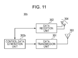
- FIG. 11 is a schematic block diagram showing a configuration of the pico base station apparatus 30 b .
- the pico base station apparatus 30 b is different from the macro base station apparatus 30 a in terms of having a control data generation unit 300 b instead of the control data generation unit 300 a and having smaller maximum transmit power of the transmission unit 301 than that of the macro base station apparatus 30 a .
- Other parts are the same so that description thereof will be omitted.
- the control data generation unit 300 b generates control information CI to be notified to the terminal apparatus 20 by referring to a channel estimation value which is input from the data reception unit 302 .
- the control data generation unit 300 b inputs the generated control information CI to the data transmission unit 301 to transmit to the terminal apparatus 20 .
- control information CI includes power control information associated with transmit power control, resource block assignment information, MCS (Modulation and Coding Scheme) information for designating a coding rate and a modulation scheme, rank information for designating the number of streams, precoding information for designating a precoding matrix, and SRS information for designating arrangement of the sounding reference signal.
- MCS Modulation and Coding Scheme
- assignment information of the resource blocks in the uplink generated by the control data generation unit 300 b is assignment information having the maximum value of the number of clusters of “2”, which is exemplified in FIG. 6 .
- control data generation unit 300 b has the interval storage unit for pico 237 shown in FIG. 3 , and determines a combination which is used by each of the terminal apparatuses 20 connected with the own apparatus from combinations of the time interval and the frequency interval which are stored in the interval storage unit for pico 237 .
- the control data generation unit 300 b generates SRS information which includes an index of the determined combination.
- control data generation unit 300 b inputs the resource block assignment information, the MCS information, the rank information and the precoding information of the generated control information CI to the data reception unit 302 . Further, the control data generation unit 300 b generates information showing arrangement of the sounding reference signal according to the SRS information of the generated control information CI to input to the data reception unit 302 .
- the frequency selection diversity gain is not expected at all between the terminal apparatus 20 and the pico base station apparatus 30 b
- notification of resource block assignment information which is used is not performed at all for each communication opportunity from the pico base station apparatus 30 b to the terminal apparatus 20 (it is set that in the case where the terminal apparatus 20 communicates with the macro bases station apparatus 30 a , notification of resource block assignment information which is used is performed for each communication opportunity from the macro base station apparatus 30 a to the terminal apparatus 20 )
- each of the base station apparatuses determines arrangement of the sounding reference signal in the present embodiment, but the arrangement of the sounding reference signal may be determined by the macro base station apparatus 20 a , or may be determined independently by the terminal apparatus 20 based on a value of an ID or the like which is specific to the terminal apparatus 20 .
- the terminal apparatus 20 performs communication with the base station by using two or more component carriers (one system band supporting LTE Rel.8), the arrangement of the sounding reference signal is able to be set for each component carrier.
- the arrangement of the sounding reference signal to be transmitted to the pico base station apparatus 30 b may be determined by the macro base station apparatus 30 a or the pico base station apparatus 30 b or may be determined independently by the terminal apparatus 20 based on a value of an ID or the like which is specific to the terminal apparatus.
- the arrangement of the sounding reference signal is able to be set for each component carrier.
- the overhead for transmission of the sounding reference signal decreases, thus making it possible to increase throughput in the uplink of the small cell.
- the terminal apparatus 20 does not transmit any sounding reference signal periodically at all.
- the terminal apparatus 20 is also able to transmit a signal for grasping situation of a channel, including the sounding reference signal, not periodically but by an instruction from the macro base station apparatus 30 a or the pico base station apparatus 30 b.
- a radio communication system 11 in the present embodiment is configured by including a macro base station apparatus 31 a , a pico base station apparatus 31 b and a terminal apparatus 21 .
- assignment of radio frequency resources to the terminal apparatus 20 is performed with a resource block which is configured with a predetermined frequency width (one or more contiguous subcarriers) as a frequency assignment unit. If the total number of subcarriers used for communication is a certain number, as the number of subcarriers which constitute the frequency assignment unit increases, the total number of the frequency assignment units decreases and the bit number of information for designating the frequency assignment unit (corresponding to the RB number of the first embodiment) decreases. On the other hand, as the number of subcarriers which constitute the frequency assignment unit increases, a difference of frequency gains in the frequency assignment unit is reduced, so that a diversity gain which is expected by selecting the frequency assignment unit at the time of communication is reduced.
- FIG. 12 is a schematic block diagram showing a configuration of a control unit 214 A of the terminal apparatus 21 .
- the terminal apparatus 21 is different from the terminal apparatus 20 of FIG. 2 only in terms of having the control unit 214 A instead of the control unit 214 .
- the control unit 214 A is different from the control unit 214 of FIG. 3 in terms of having an assignment RB judgment unit 231 A instead of the assignment.
- the RBG size storage unit for macro 240 a stores the number of resource blocks of a resource block group (RBG) in the case where the type of the destination base station is the macro base station and a system bandwidth in association with each other.
- the resource block group is a minimum frequency assignment unit in the present embodiment, and is composed of resource blocks which are contiguous in a frequency direction.
- Assignment information in the present embodiment designates the resource block which is assigned with an RBG number and the number of RBGs instead of the RB number and the number of RBs in the first embodiment.
- the RBG number is a serial number of resource block groups, and the number of RBGs indicates the number of the resource block groups.
- the number of subcarriers constituting the resource block is common in the macro base station and the pico base station, and the number of resource blocks constituting the resource block group which is the minimum frequency assignment unit is changed according to the type of the destination base station, but in the case where the resource block is set as the minimum frequency assignment unit in the present embodiment, the number of subcarriers constituting the resource block may be changed according to the type of the destination base station.
- the RBG size storage unit for pico 240 b stores the number of resource blocks of a resource block group in the case where the type of the destination base station is the pico base station and the system bandwidth in association with each other. Note that, a range of the present invention is not departed also in the case where the RBG size storage unit for pico 240 b does not store the number of resource blocks of a resource block group in the case where the type of the destination base station is the pico base station and the system bandwidth in association with each other (a case where the predetermined number of resource blocks of a resource block group is used regardless of the system bandwidth in the case where the type of the destination base station is the pico base station).
- the number of resource blocks stored in association with each system bandwidth by the RBG size storage unit for pico 240 b is larger than the number of resource blocks stored in association with the same system bandwidth by the RBG size storage unit for macro 240 a .
- maximum values of the RBG number and the number of RBGs become smaller than the case where the type of the destination base station is the macro base station. That is, since the bit numbers of the RBG number and the number of RBGs decrease, the bit number of assignment information also decreases, thus making it possible to reduce overhead by the assignment information and achieve excellent transmission efficiency.
- the assignment RB judgment unit 231 A determines the number of resource blocks of a resource block group RBG by using the type of the destination base station and the system bandwidth. In the event of determining the number of resource blocks of the resource block group RBG, the assignment RB judgment unit 231 A refers to the RBG size storage unit for macro 240 a or the RBG size storage unit for pico 240 b according to the type of the destination base station which is acquired from the base station type judgment unit 232 . The assignment RB judgment unit 231 A uses the determined number of resource blocks to judge resource blocks indicated by assignment information extracted by the assignment information extraction unit 230 .
- FIG. 13 is a view showing an example of a storage content of the RBG size storage unit for macro 240 a .
- the RBG size storage unit for macro 240 a stores the system bandwidth “5 MHz” and the number of resource blocks of a resource block group “2” in association with each other.
- the system bandwidth “10 MHz” and the number of resource blocks “3” are stored in association with each other
- the system bandwidth “15 MHz” and the number of resource blocks “4” are stored in association with each other
- the bandwidth “20 MHz” and the number of resource blocks “5” are stored in association with each other.
- FIG. 14 is a view showing an example of a storage content of the RBG size storage unit for pico 240 b .
- the RBG size storage unit for macro 240 b stores the system bandwidth “5 MHz” and the number of resource blocks of the resource block group “4” in association with each other.
- the system bandwidth “10 MHz” and the number of resource blocks “6” are stored in association with each other
- the system bandwidth “15 MHz” and the number of resource blocks “8” are stored in association with each other
- the bandwidth “20 MHz” and the number of resource blocks “10” are stored in association with each other.
- the number of resource blocks, which is stored in association with each system bandwidth by the RBG size storage unit for pico 240 b is larger than the number of resource blocks, which is stored in association with the same system bandwidth by the RBG size storage unit for macro 240 a .
- the system bandwidth 10 MHz is stored in association with “6” by the RBG size storage unit for macro 240 a , but is stored in association with “3” by the RBG size storage unit for pico 240 b.
- the macro base station apparatus 31 a is different from the macro base station apparatus 30 a of FIG. 10 in terms of having a control data generation unit 310 a instead of the control data generation unit 300 a .
- the control data generation unit 310 a generates control information CI in the same manner as the control data generation unit 300 a , but has the RBG size storage unit for macro 240 a and is different from the control data generation unit 300 a in terms of performing scheduling and generation of assignment information with a resource block group with the number of resource blocks that is determined by referring to this storage unit as the frequency assignment unit.
- the pico base station apparatus 31 b is different from the pico base station apparatus 30 b of FIG. 11 in terms of having a control data generation unit 310 b instead of the control data generation unit 300 b .
- the control data generation unit 310 b generates control information CI in the same manner as the control data generation unit 300 b , but has the RBG size storage unit for pico 240 b and is different from the control data generation unit 300 b in terms of performing scheduling and generation of assignment information with a resource block group with the number of resource blocks that is determined by referring to this storage unit as the frequency assignment unit.
- a radio communication system 12 in the present embodiment is configured by including a macro base station apparatus 32 a , a pico base station apparatus 32 b and a terminal apparatus 22 .
- the terminal apparatus 22 selects an access scheme and also selects a modulation scheme and a coding rate.
- a total number of these combinations in the small cell is made smaller than a total number of combination in the macro cell. Since there is a margin in transmit power of the terminal apparatus 22 particularly in the small cell, the modulation scheme and the coding rate with a low transmission rate may not be used. This is because in the case where performances (error rate performances) are deteriorated in communication, it is possible to deal with it by increasing the transmit power because of the margin in the transmit power in the same manner as the first embodiment.
- FIG. 15 is a schematic block diagram showing a configuration of a control unit 214 B of the terminal apparatus 22 .
- the terminal apparatus 22 is different from the terminal apparatus 20 of FIG. 2 only in terms of having the control unit 214 B instead of the control unit 214 .
- the control unit 214 B is different from the control unit 214 of FIG. 3 in terms of having an MCS determination unit 239 B instead of the MCS determination unit 239 and having an MCS storage unit for macro 241 a and an MCS storage unit for pico 241 b.
- the MCS storage unit for macro 241 a stores the combination of the modulation scheme and the coding rate in association with a value of MCS information.
- the MCS storage unit for pico 241 b stores the combination of the modulation scheme and the coding rate in association with a value of MCS information.
- the combinations of the modulation scheme and the coding rate stored in the MCS storage unit for pico 241 b are obtained by excluding a combination with a low transmission rate from the combinations stored in the MCS storage unit for macro 241 a.
- the MCS determination unit 239 B determines the modulation scheme and the coding rate by extracting MCS information from the control information CI in the same manner as the MCS determination unit 239 . However, it is different from the MCS determination unit 239 in terms of that in the case where the type of the destination base station is the macro base station, the MCS storage unit for macro 241 a is referred to and the pico base station refers to the MCS storage unit for pico 241 b .
- the MCS determination unit 239 B reads a modulation scheme and a coding rate which are associated with a value of MCS information from the MCS storage unit for macro 241 a and notifies the coding unit 201 of the modulation schema and the coding rate.
- the MCS determination unit 239 B reads a modulation scheme and a coding rate which are associated with a value of MCS information from the MCS storage unit for pico 241 b and notifies the coding unit 201 of the modulation scheme and the coding rate.
- FIG. 16 is a view showing an example of a storage content of the MCS storage unit for macro 241 a .
- the combination of the modulation scheme “BPSK” and the coding rate R “1/3” is stored in association with the value of MCS “000”.
- the combination of the modulation scheme “BPSK” and the coding rate R “1/2” is stored in association with the value of MCS “001”
- the combination of the modulation scheme “QPSK” and the coding rate R “1/3” is stored in association with the value of MCS “010”
- the combination of the modulation scheme “QPSK” and the coding rate R “1/2” is stored in association with the value of MCS “011”.
- the combination of the modulation scheme “16QAM” and the coding rate R “1/3” is stored in association with the value of MCS “100”
- the combination of the modulation scheme “16QAM” and the coding rate R “1/2” is stored in association with the value of MCS “101”
- the combination of the modulation scheme “64QAM” and the coding rate R “1/3” is stored in association with the value of MCS “110”
- the combination of the modulation scheme “64QAM” and the coding rate R “1/2” is stored in association with the value of MCS “111”.
- FIG. 17 is a view showing an example of a storage content of the MCS storage unit for pico 241 b .
- the values of MCS from “100” to “111” are the same as in the example of the storage content of the MCS storage unit for macro 241 a of FIG. 16 , but not used (“Not Used”) is given for the values of MCS from “000” to “011” with a low transmission rate.
- the macro base station apparatus 32 a is different from the macro base station apparatus 30 a of FIG. 10 in terms of having a control data generation unit 320 a instead of the control data generation unit 300 a .
- the control data generation unit 320 a generates the control information CI in the same manner as the control data generation unit 300 a , but is different from the control data generation unit 300 a in terms of having the MCS storage unit for macro 241 a and performing generation of MCS information which is determined by referring to this storage unit.
- the pico base station apparatus 32 b is different from the pico base station apparatus 30 b of FIG. 11 in terms of having a control data generation unit 320 b instead of the control data generation unit 300 b .
- the control data generation unit 320 b generates the control information CI in the same manner as the control data generation unit 300 b , but is different from the control data generation unit 300 b in terms of having the MCS storage unit for pico 241 b and performing generation of MCS information which is determined by referring to this storage unit.
- the storage content of the MCS storage unit for pico 241 b may be like an example shown in FIG. 18 .
- the values of MCS from “010” to “111” are the same as in the example of the storage content of the MCS storage unit for macro 241 a of FIG. 16 .
- the modulation scheme “256QAM” and the coding rate R “1/3”, and the modulation scheme “256QAM” and the coding rate R “1/2” are associated with the values of MCS of “000” and “001” with a low transmission rate. That is, the combination having a higher transmission rate than all the combinations stored in the MCS storage unit for macro 241 a is associated. This makes it possible to use a combination of a modulation scheme and a coding rate having a high transmission rate for the small cell without increasing the bit number of MCS information and to achieve excellent transmission efficiency.
- a radio communication system 13 in the present embodiment is configured by including a macro base station apparatus 33 a , a pico base station apparatus 33 b and a terminal apparatus 23 .
- the terminal apparatus 23 selects the number of streams (rank) and a precoding pattern (precoding matrix).
- the number of combinations of the number of streams and the precoding pattern increases, the number of streams and the precoding pattern more suitable for a channel are able to be selected, thus making it possible to improve throughput.
- a quantity of control information which is demanded to designate a selected combination increases.
- a total number of these combinations in the small cell is made smaller than a total number of the combinations in the macro cell.
- the small cell which is a service area of the pico base station apparatus 33 b has a narrow cell range, distance attenuation between the pico base station apparatus 33 b and the terminal apparatus 23 is suppressed. Therefore, in the same manner as the first embodiment, there is a margin in transmit power of the terminal apparatus 23 , and deterioration of communication quality due to increase in the number of streams is able to be compensated for by increasing the transmit power.
- the number of streams used for transmission by the terminal apparatus 23 is set to a predetermined value or more.
- the total number of the combinations of the number of streams and the precoding pattern decreases, thus making it possible to reduce the bit number in the event of designating the number of streams and the precoding pattern to the terminal apparatus.
- FIG. 19 is a schematic block diagram showing a configuration of a control unit 214 C of the terminal apparatus 23 .
- the terminal apparatus 23 is different from the terminal apparatus 20 of FIG. 2 only in terms of having the control unit 214 C instead of the control unit 214 .
- the control unit 214 C is different from the control unit 214 of FIG. 3 in terms of having a precoding determination unit 238 C instead of the precoding determination unit 238 and having a pattern storage unit for macro 242 a and a pattern storage unit for pico 242 b.
- the pattern storage unit for macro 242 a stores the combination of the number of streams and the precoding pattern in the case where the type of the destination base station is the macro base station in association with an index.
- the pattern storage unit for pico 242 b stores the combination of the number of streams and the precoding pattern in the case where the type of the destination base station is the pico base station in association with the index.
- the number of streams in the combination stored in the pattern storage unit for pico 242 b is limited to only “2”.
- the bit number of the indexes indicating the combinations in the small cell decreases so that it is possible to reduce overhead by control information for designating the number of streams and the precoding pattern and to achieve excellent transmission efficiency.
- the precoding determination unit 238 C extracts the index from the control information CI in the same manner as the precoding determination unit 238 and determines the number of streams and the precoding matrix. However, it is different from the precoding determination unit 238 in terms of that the pattern storage unit for macro 242 a is referred to in the case where the type of the destination base station is the macro base station and the pico base station refers to the pattern storage unit for pico 242 b.
- FIG. 20 is a view showing an example of a storage content of the pattern storage unit for macro 242 a .
- the number of streams “1” and the precoding pattern “pattern 0 ” are stored in association with the index “0”.
- the number of streams “1” and the precoding pattern “pattern 1 ” are stored in association with the index “1”, . . .
- the number of streams “1” and the precoding pattern “pattern 23 ” are stored in association with the index “23”
- the number of streams “2” and the precoding pattern “pattern 0 ” are stored in association with the index “24”
- the number of streams “2” and the precoding pattern “pattern 15 ” are stored in association with the index “39”.
- FIG. 21 is a view showing an example of a storage content of the pattern storage unit for pico 242 b .
- the indexes from “24” to “39” are the same as in the example of the storage content of the pattern storage unit for macro 242 a of FIG. 20 , but not used (“Not Used”) is given for the indexes from “0” to “23” in which the number of streams is “1” in the pattern storage unit for macro 242 a.
- the macro base station apparatus 33 a is different from the macro base station apparatus 30 a of FIG. 10 in terms of having a control data generation unit 330 a instead of the control data generation unit 300 a .
- the control data generation unit 330 a generates the control information CI in the same manner as the control data generation unit 300 a , but is different from the control data generation unit 300 a in terms of having the pattern storage unit for macro 242 a and performing generation of the control information CI including the index according to the combination of the number of streams and the precoding patter determined by referring to this storage unit.
- the pico base station apparatus 33 b is different from the pico base station apparatus 30 b of FIG. 11 in terms of having a control data generation unit 330 b instead of the control data generation unit 300 b .
- the control data generation unit 330 b generates the control information CI in the same manner as the control data generation unit 300 b , but is different from the control data generation unit 300 b in terms of having the pattern storage unit for pico 242 b and performing generation of the control information CI including the index according to the combination of the number of streams and the precoding patter determined by referring to this storage unit.
- the indexes for designating the numbers of streams and the precoding patterns need 6 bits.
- the indexes for designating the numbers of streams and the precoding patterns are able to be set to 4 bits, thus making it possible to reduce information for designating the numbers of streams and the precoding patterns by 2 bits. This makes it possible to suppress overhead by the indexes for designating the numbers of streams and the precoding patterns and achieve excellent transmission efficiency.
- each apparatus may be realized by recording a program for realizing functions or a part of functions of each of the terminal apparatuses 20 , 21 , 22 and 23 , the macro base station apparatuses 30 a , 31 a , 32 a and 33 a , and the pico base station apparatuses 30 b , 31 b , 32 b and 33 b in each of the embodiments in a computer readable recording medium and causing a computer system to read this program recorded in the recording medium for execution.
- the “computer system” which is referred to here includes an OS and hardware such as peripheral equipment.
- the “computer readable recording medium” refers to a portable medium such as a flexible disk, a magneto-optical disk, a ROM or a CD-ROM, or a storage apparatus such as a hard disk installed in the computer system. Furthermore, the “computer readable recording medium” also includes one for holding a program dynamically for a short time period like a communication line in a case where a program is transmitted via a network such as the Internet or a communication line such as a telephone line, and one for holding a program for a fixed period of time like a volatile memory inside a computer system serving as a server or a client in such a case. In addition, the aforementioned program may be one for realizing a part of the functions described above, and further may be one capable of realizing the functions described above in combination with a program which has been already recorded in the computer system.
- each of the terminal apparatuses 20 , 21 , 22 and 23 , the macro base station apparatuses 30 a , 31 a , 32 a and 33 a , and the pico base station apparatuses 30 b , 31 b , 32 b and 33 b in each of the aforementioned embodiments may be realized typically as an LSI which is an integrated circuit.
- Each functional block of the terminal apparatuses 20 , 21 , 22 and 23 , the macro base station apparatuses 30 a , 31 a , 32 a and 33 a , and the pico base station apparatuses 30 b , 31 b , 32 b and 33 b may be chipped individually, or a part or all thereof may be chipped being integrated. Further, a method for making into an integrated circuit is not limited to the LSI and a dedicated circuit or a versatile processor may be used for realization. Any of hybrid one and monolithic one may be used. The functions may be realized partially by hardware and partially by software.
- an integrated circuit by this technology may be also used.
- an aspect of the present invention is a terminal apparatus which performs communication with a first base station apparatus and a second base station apparatus which has smaller maximum transmit power than that of the first base station apparatus, including a control unit that extracts control information from signals received from the first base station apparatus and the second base station apparatus and sets communication parameters of an uplink data signal, in which a bit number which is extracted by the control unit as the control information from the signal from the second base station apparatus is smaller than a bit number which is extracted as the control information from the signal from the first base station apparatus.
- an aspect of the present invention is the aforementioned terminal apparatus, in which the control information may include at least frequency assignment information of uplink data transmission, and an upper limit of a number of clusters that are able to be arranged by using the frequency assignment information by the control unit may be smaller in a case where the control information from the second base station apparatus is used than a case where the control information from the first base station is used.
- an aspect of the present invention is the aforementioned terminal apparatus, in which the control information may include at least frequency assignment information of uplink data transmission, and a minimum frequency assignment unit at the time of arrangement by using the frequency assignment information by the control unit may be larger in a case where the control information from the second base station apparatus is used than a case where the control information from the first base station is used.
- an aspect of the present invention is a terminal apparatus that performs communication of data with a first base station apparatus and a second base station apparatus which has smaller maximum transmit power than that of the first base station apparatus, in which a first range which is a range of communication parameters usable in the case of performing communication of data with the first base station apparatus and a second range which is a range of communication parameters usable in the case of performing communication of data with the second base station apparatus are different.
- an aspect of the present invention is the aforementioned terminal apparatus, in which a total number of the communication parameters included in the first range may be smaller than a total number of the communication parameters included in the second range.
- the second base station apparatus has smaller maximum transmit power than that of the first base station apparatus, and therefore has a narrower communication range than that of the first base station apparatus. Accordingly, since same situation as a cell end of the first base station apparatus does not occur in the terminal apparatus which communicates with the second base station apparatus, it is possible to maintain sufficient transmission quality even if a value of the communication parameter used in this situation falls out of the second range.
- an aspect of the present invention is any of the aforementioned terminal apparatuses, in which a frequency signal may be set to one or a plurality of clusters, each of the clusters may be transmitted being arranged in a predetermined frequency, and the communication parameter may be the number of clusters.
- the number of clusters in a case where communication is performed between the second base station apparatus and the terminal apparatus is made smaller than a case where communication is performed between the first base station apparatus and the terminal apparatus, and the information quantity of the control information for sharing a frequency at which each of the clusters is arranged is reduced, thus making it possible to achieve excellent transmission efficiency.
- an aspect of the present invention is any of the aforementioned terminal apparatuses, in which a communication parameter having the worst transmission efficiency of the communication parameters included in the first range may not be included in the second range.
- the second base station apparatus has smaller maximum transmit power than that of the first base station apparatus, and therefore has a narrower communication range than that of the first base station apparatus. Accordingly, in the case of performing communication with the second base station apparatus, even if the parameter having the worst transmission efficiency of the first range is not used, it is possible to maintain sufficient transmission quality.
- an aspect of the present invention is any of the aforementioned terminal apparatuses, in which a communication parameter having the most excellent transmission efficiency of the communication parameters included in the second range may not be included in the first range.
- the second base station apparatus has smaller maximum transmit power than that of the first base station apparatus, and therefore has a narrower communication range than that of the first base station apparatus. Accordingly, in the case of performing communication with the second base station apparatus, even if the communication parameter having more excellent transmission efficiency than that of the case of performing communication with the first base station apparatus is used, it is possible to maintain sufficient transmission quality.
- an aspect of the present invention is any of the aforementioned terminal apparatuses, in which the communication parameters may be a combination of a number of streams and a precoding pattern.
- an aspect of the present invention is any of the aforementioned terminal apparatuses, in which the communication parameters may be a combination of a modulation scheme and a coding rate.
- an aspect of the present invention is a processor in a terminal apparatus that performs communication of data with a first base station apparatus and a second base station apparatus which has smaller maximum transmit power than that of the first base station apparatus, in which a first range which is a range of communication parameters usable in the case of performing communication of data with the first base station apparatus and a second range which is a range of communication parameters usable in the case of performing communication of data with the second base station apparatus are different.
- an aspect of the present invention is a communication method in a terminal apparatus that performs communication of data with a first base station apparatus and a second base station apparatus which has smaller maximum transmit power than that of the first base station apparatus, including: a first process that the terminal apparatus performs communication of data with the first base station apparatus; and a second process that the terminal apparatus performs communication of data with the second base station apparatus, in which a first range which is a range of communication parameters usable at the first process and a second range which is a range of communication parameters usable at the second process are different.
- an aspect of the present invention is a terminal apparatus that performs communication of data with a first base station apparatus and a second base station apparatus which has smaller maximum transmit power than that of the first base station apparatus, in which an arrangement interval of a sounding reference signal which is used with the second base station apparatus is larger than an arrangement interval of a sounding reference signal which is used with the first base station apparatus.
- the second base station apparatus has smaller maximum transmit power than that of the first base station apparatus, and therefore has a narrower communication range than that of the first base station apparatus. Accordingly, since the arrangement interval of the sounding reference signal is wide in the case of performing communication with the second base station apparatus, it is possible to maintain sufficient transmission quality even if accuracy of a channel state which is measured by using the sounding reference signal is deteriorated.
- an aspect of the present invention is a processor in a terminal apparatus that performs communication of data with a first base station apparatus and a second base station apparatus which has smaller maximum transmit power than that of the first base station apparatus, in which a minimum value of an arrangement interval that is able to be set of the sounding reference signal which is used with the second base station apparatus is larger than a minimum value of an arrangement interval that is able to be set of the sounding reference signal which is used with the first base station apparatus.
- an aspect of the present invention is a communication method in a terminal apparatus that performs communication of data with a first base station apparatus and a second base station apparatus which has smaller maximum transmit power than that of the first base station apparatus, including: a first process of transmitting and receiving a sounding reference signal between the terminal apparatus and the first base station apparatus; and a second process of transmitting and receiving a sounding reference signal between the terminal apparatus and the second base station apparatus, in which an arrangement interval of the sounding reference signal which is used at the second process is larger than an arrangement interval of the sounding reference signal which is used at the first process.
- an aspect of the present invention is a terminal apparatus that performs communication of data with a first base station apparatus and a second base station apparatus which has smaller maximum transmit power than that of the first base station apparatus, in which a frequency width of a minimum frequency assignment unit in the case of performing communication of data with the second base station apparatus is larger than a frequency width of a minimum frequency assignment unit in the case of performing communication of data with the first base station apparatus.
- the second base station apparatus has smaller maximum transmit power than that of the first base station apparatus, and therefore has a narrower communication range than that of the first base station apparatus. Accordingly, since the frequency width of the minimum frequency assignment unit is large in the case of performing communication with the second base station apparatus, even if flexibility of frequency assignment decreases and a channel state of a frequency which is able to be assigned is deteriorated, it is possible to maintain sufficient transmission quality.
- an aspect of the present invention is a processor in a terminal apparatus that performs communication of data with a first base station apparatus and a second base station apparatus which has smaller maximum transmit power than that of the first base station apparatus, in which a frequency width of a minimum frequency assignment unit in the case of performing communication of data with the second base station apparatus is larger than a frequency width of a minimum frequency assignment unit in the case of performing communication of data with the first base station apparatus
- an aspect of the present invention is a communication method in a terminal apparatus that performs communication of data with a first base station apparatus and a second base station apparatus which has smaller maximum transmit power than that of the first base station apparatus, including: a first process that the terminal apparatus performs communication of data with the first base station apparatus; and a second process that the terminal apparatus performs communication of data with the second base station apparatus, in which a frequency width of a minimum frequency assignment unit at the second process is larger than a frequency width of a minimum frequency assignment unit at the first process.
- an aspect of the present invention is a terminal apparatus that performs communication of data with a first base station apparatus and a second base station apparatus which has smaller maximum transmit power than that of the first base station apparatus, in which in the case of performing communication of data with the first base station apparatus, the communication of the data is performed by using a frequency resource which is designated to the first base station apparatus for each communication opportunity, and in the case of performing communication of data with the second base station apparatus, the communication of the data is performed by using a predefined frequency resource.
- the control information for sharing frequency assignment between the second base station apparatus and the terminal apparatus is eliminated, thus making it possible to achieve excellent transmission efficiency.
- the second base station apparatus has smaller maximum transmit power than that of the first base station apparatus, and therefore has a narrower communication range than that of the first base station apparatus. Accordingly, in the case of performing communication with the second base station apparatus, even if a channel state of a frequency to be used is deteriorated, it is possible to maintain sufficient transmission quality.
- an aspect of the present invention is a processor in a terminal apparatus that performs communication of data with a first base station apparatus and a second base station apparatus which has smaller maximum transmit power than that of the first base station apparatus, in which in the case of performing communication of data with the first base station apparatus, the communication of the data is performed by using a frequency resource which is designated to the first base station apparatus for each communication opportunity, and in the case of performing communication of data with the second base station apparatus, the communication of the data is performed by using a predefined frequency resource.
- an aspect of the present invention is a communication method in a terminal apparatus that performs communication of data with a first base station apparatus and a second base station apparatus which has smaller maximum transmit power than that of the first base station apparatus, including: a first process that the terminal apparatus performs communication of data with the first base station apparatus; and a second process that the terminal apparatus performs communication of data with the second base station apparatus, in which the communication of the data is performed by using a frequency resource which is designated to the first base station apparatus for each communication opportunity at the first process, and the communication of the data is performed by using a predefined frequency resource at the second process.
- an aspect of the present invention is a terminal apparatus that performs communication of data with a first base station apparatus and a second base station apparatus which has smaller maximum transmit power than that of the first base station apparatus, in which communication of a sounding reference signal is performed periodically with the first base station apparatus, and communication of a sounding reference signal is performed with the second base station apparatus in response to a request.
- the second base station apparatus has smaller maximum transmit power than that of the first base station apparatus, and therefore has a narrower communication range than that of the first base station apparatus. Accordingly, since a channel state is able to be measured by the sounding reference signal only upon the request in the case of performing communication with the second base station apparatus, it is possible to maintain sufficient transmission quality even if accuracy of the measured channel state is deteriorated.
- an aspect of the present invention is a processor in a terminal apparatus that performs communication of data with a first base station apparatus and a second base station apparatus which has smaller maximum transmit power than that of the first base station apparatus, in which communication of a sounding reference signal is performed periodically with the first base station apparatus, and communication of a sounding reference signal is performed with the second base station apparatus in response to a request.
- an aspect of the present invention is a communication method in a terminal apparatus that performs communication of data with a first base station apparatus and a second base station apparatus which has smaller maximum transmit power than that of the first base station apparatus, including a first process of performing communication of a sounding reference signal periodically with the first base station apparatus, and a second process of performing communication of a sounding reference signal with the second base station apparatus in response to a request.
- an aspect of the present invention is any of the aforementioned terminal apparatuses, in which a power control unit that controls transmit power in the case of transmitting a signal is included, and the control unit may be configured so as to set transmit power in the case of transmitting the signal to the second base station apparatus to be higher than transmit power in the case of transmitting the signal to the first base station apparatus having same channel loss with respect to the power control unit.
- the terminal apparatus is able to use communication parameters having more excellent transmission efficiency in the case of transmitting to the second base station apparatus than the case of transmitting to the first base station apparatus, thus making it possible to achieve excellent transmission efficiency.
- the present invention is applicable to a mobile telephone, a personal computer, a tablet-type computer and the like.
Abstract
A terminal apparatus, which performs communication with a first base station apparatus and a second base station apparatus which has a smaller maximum transmit power than that of the first base station apparatus, includes a control unit that extracts control information from signals received from the first base station apparatus and the second base station apparatus and sets communication parameters of an uplink data signal, in which a bit number of information which is extracted by the control unit as the control information from the signal from the second base station apparatus is smaller than a bit number of information which is extracted as the control information from the signal from the first base station apparatus.
Description
The present invention relates to a terminal apparatus.
This application claims priority based on Japanese Patent Application No. 2012-256727 filed in Japan on Nov. 22, 2012, the content of which is incorporated herein.
These days, in a mobile communication system, a band of a transmission band is being widened as demands for large capacity communication are increased, and a shortage of an available radio frequency resource becomes a problem accordingly. In order to improve frequency use efficiency with a limited radio frequency resource, increasing communication capacity by an MIMO (Multiple-Input Multiple-Output) transmission technology is regarded as being effective, but there is a limit on increase in the number of antennas due to a problem of an apparatus scale.
Thus, for example, it has been considered in NPL 1 etc., that in addition to a conventional cellular system in which a cell is formed so that each of macro base stations with the same scale covers different communication areas, by newly arranging a pico base station having a communication area smaller than that of the macro base station in a cell to form a new cell, it is sought to subdivide a′ communication area per base station to increase communication capacity (hereinafter, a cell formed by the macro base station is referred to as a macro cell, and a cell formed by the pico base station is referred to as a small cell). As one example, in a case where a lot of terminal apparatuses exist in a macro cell in which a small cell is formed, the macro base station instructs a terminal apparatus which is positioned in the small cell to connect with the pico base station. By connecting the terminal apparatus which has received the instruction with the pico base station, a load imposed on the macro base station is able to be offloaded to the pico base station, resulting that transmission opportunities of all terminal apparatuses in the macro cell are able to be increased.
In the cellular system, typically, capability of a power amplifier is limited in a terminal apparatus which is desired to be downsized. Therefore, in uplink, a transmission scheme of a transmit signal is desired to have a PAPR (Peak to Average Power Ratio) as low as possible in order to seek linear amplification with high efficiency. In the LTE-A (Long Term Evolution-Advanced) standard which is actually specified these days, DFT-S-OFDM (Discrete Fourier Transform Spread Orthogonal Frequency Division Multiplexing; also referred to as SC-FDMA (Single Carrier Frequency Division Multiple Access)) and Clustered DFT-S-OFDM based on single carrier transmission having excellent PAPR performances are employed as the transmission scheme of the uplink.
NPL 1: NTT DOCOMO, “Enhanced Cell Identification for Additional Carrier Type”, 3GPP, 3GPP TSG RAN WG1 Meeting #68 R1-120398
In the small cell, however, the terminal apparatus has remaining transmit power because the cell is small, and there is a problem that excellent transmission efficiency is not able to be achieved if the terminal apparatus is controlled in the same manner as the macro cell.
The present invention has been made in view of such circumstances, and an object thereof is to provide a terminal apparatus which achieves excellent transmission efficiency in a mobile communication system in which a small cell is arranged in a macro cell.
(1) This invention has been made for solving the aforementioned problems, and an aspect of the present invention is a terminal apparatus capable of transmitting a signal to a first communication apparatus and a second communication apparatus, including: a reception unit that receives information associated with the first communication apparatus or the second communication apparatus from the first communication apparatus; a control unit that switches a maximum number of clusters used for transmission of the signal based on the information; and a transmission unit that transmits the signal by using the maximum number of clusters, which is switched by the control unit, in which the control unit uses different maximum numbers of clusters between a case where the signal is transmitted to the first communication apparatus based on the information and a case where the signal is transmitted to the second communication apparatus based on the information.
(2) Moreover, another aspect of the present invention is a first communication apparatus capable of transmitting a signal to a terminal apparatus, including a transmission unit that transmits, to the terminal apparatus, information used for determining to which of the first communication apparatus and a second communication apparatus that is different from the first communication apparatus the signal is to be transmitted by the terminal apparatus.
(3) Moreover, another aspect of the present invention is a communication method in a terminal apparatus capable of transmitting a signal to a first communication apparatus and a second communication apparatus, including: a first step of receiving information associated with the first communication apparatus or the second communication apparatus from the first communication apparatus; a second step of switching a maximum number of clusters used for transmission of the signal based on the information; and a third step of transmitting the signal by using the maximum number of clusters, which is switched in the second step, in which the second step uses different maximum numbers of clusters between a case where the signal is transmitted to the first communication apparatus based on the information and a case where the signal is transmitted to the second communication apparatus based on the information.
(4) Moreover, another aspect of the present invention is a communication method in a first communication apparatus capable of transmitting a signal to a terminal apparatus, including a step of transmitting, to the terminal apparatus, information used for determining to which of the first communication apparatus and a second communication apparatus that is different from the first communication apparatus the signal is to be transmitted by the terminal apparatus.
According to aspects of this invention, excellent transmission efficiency is achieved in a mobile communication system in which a small cell is arranged in a macro cell.
Description will hereinafter be given for embodiments of the present invention with reference to drawings. Description will be given in each embodiment below on the premise of uplink in a cellular system, but the same invention is applicable also to downlink. Note that, in a case of applying to the downlink, such a method for using an access scheme having excellent transmission performances in a base station having large transmit power (for example, a macro base station) and using an access scheme having good power efficiency in a base station having small transmit power (for example, a power-saving base station including a pico base station and a femto base station) is also considered, so that the downlink is also included in the present invention. Further, description will be given for the access scheme on the premise of DFT-S-OFDM (SC-FDMA) and Clustered DFT-S-OFDM which are access schemes of a single carrier base, but it is effective for other schemes which use a plurality of subcarriers including simple OFDM.
Moreover, a terminal apparatus discriminates the macro base station and the pico base station according to a measure of maximum transmit power of the downlink in each embodiment. From each of the base stations, information associated with maximum transmit power of the base stations may be notified to the terminal apparatus in the downlink, or from the macro base station, information associated with maximum transmit power of its own station and the pico base station may be notified to the terminal apparatus. Other identification methods are of course not excluded from the present invention.
[First embodiment]
The coding unit 201-1 performs error correction coding of a bit sequence of a first stream, and then performs modulation such as BPSK (Binary Phase Shift Keying), QPSK (Quaternary Phase Shift Keying), or 16QAM (16-ary guadrature amplitude modulation) to generate a symbol string. The coding unit 201-2 performs same processing for a bit sequence of a second stream. Note that, both the coding units 201-1 and 201-2 follow designation from the control unit 214 as to a coding rate at the time of the error correction coding and the modulation scheme at the time of the modulation.
The S/P conversion unit 202-1 performs serial/parallel conversion for the symbol string generated by the coding unit 201-1. Note that, a parallel number of a serial/parallel conversion result is matched with a DFT point number in the DFT unit 203-1. The S/P conversion unit 202-2 performs same processing for a symbol string generated by the coding unit 201-2.
The DFT unit 203-1 performs discrete Fourier transform for the conversion result by the S/P conversion unit 202-1 to generate a discrete spectrum. The DFT unit 203-2 performs same processing for a conversion result by the S/P conversion unit 202-2. The power control unit 204-1 multiplies the discrete spectrum generated by the DFT unit 203-1 by a coefficient designated from the control unit 214. The power control unit 204-2 multiplies a discrete spectrum generated by the DFT unit 203-2 by a coefficient designated from the control unit 214.
The RB assignment unit 205-1 arranges the discrete spectrum which is multiplied by the coefficient at the power control unit 204-1 in a resource block designated from the control unit 214 and generates a frequency signal of the first stream. The RB assignment unit 205-2 performs same processing for the discrete spectrum which is multiplied by the coefficient at the power control unit 204-2 and generates a frequency signal of the second stream. Note that, here, the resource block is configured by one or more contiguous subcarriers and a continuous time width for a one symbol time or more, and is a minimum assignment unit in the event that the macro base station apparatus 30 a and the pico base station apparatus 30 b assign a radio resource to the terminal apparatus 20.
The precoding unit 206 multiplies a precoding matrix designated from the control unit 214 by vector composed of the frequency signal of the first stream and the frequency signal of the second stream and calculates the frequency signal for each of the transmit antenna units 213-1 and 213-2. Note that, in the case where the number of streams is one, the precoding matrix designated from the control unit 214 is multiplied by the frequency signal of the first stream and the frequency signal for each of the transmit antenna units 213-1 and 213-2 is calculated.
The SRS multiplex unit 207-1 multiplexes the frequency signal for the transmit antenna unit 213-1, which is generated by the precoding unit 206, with a sounding reference signal. The SRS multiplex unit 207-2 multiplexes the frequency signal for the transmit antenna unit 213-2 with the sounding reference signal in the same manner. The IDFT unit 208-1 performs inverse Fourier transform for the frequency signal which is multiplexed with the sounding reference signal by the SRS multiplex unit 207-1 and generates a time signal for the transmit antenna unit 213-1. The IDFT unit 208-2 performs the same for the frequency signal which is multiplexed with the sounding reference signal by the SRS multiplex unit 207-2 and generates a time signal for the transmit antenna unit 213-2. Note that, a DFT point number in the event of performing the inverse Fourier transform is a point number according to a system bandwidth. Moreover, the sounding reference signal is a signal for grasping a state of a channel. The state of the channel, which is grasped with the signal, is used in the event of determining the radio resource to be assigned to the terminal apparatus 20, etc.
The CP insertion unit 209-1 inserts a cyclic prefix to the time signal generated by the IDFT unit 208-1. Specifically, a signal of a predetermined point number from an end of a symbol zone in the time signal generated by the IDFT unit 208-1 is copied to be inserted at a head of the symbol zone. Accordingly, the parallel number of the time signal input to the CP insertion unit 209-1 is the point number according to the system bandwidth, while the parallel number of the signal in which the cyclic prefix is inserted by the CP insertion unit 209-1 is a number obtained by adding the point number for copying to the point number according to the system bandwidth. The CP insertion unit 209-2 performs processing in the same manner for the time signal generated by the IDFT unit 208-2.
The P/S conversion unit 210-1 performs parallel/serial conversion for the signal in which the cyclic prefix is inserted by the CP insertion unit 209-1 to generate a serial signal. The P/S conversion unit 210-2 performs same processing for the signal in which the cyclic prefix is inserted by the CP insertion unit 209-2. The D/A conversion unit 211-1 performs digital/analog conversion of the serial signal generated by the P/S conversion unit 210-1 to generate an analog signal. The D/A conversion unit 211-2 performs same processing for a serial signal generated by the P/S conversion unit 210-2.
The RF unit 212-1 up-converts the analog signal generated by the D/A conversion unit 211-1 to a radio frequency, which is subjected to radio transmission from the transmit antenna unit 213-1. The RF unit 212-2 up-converts the analog signal generated by the D/A conversion unit 211-2 to a radio frequency, which is subjected to radio transmission from the transmit antenna unit 213-2.
The receive antenna unit 220 receives signals transmitted by the macro base station apparatus 30 a and the pico base station apparatus 30 b. The reception unit 221 detects control information CI from the signals received by the receive antenna unit 220 to input to the control unit 214. This control information CI includes power control information associated with transmit power control, resource block assignment information, MCS (Modulation and Coding Scheme) information for designating a coding rate and a modulation scheme, rank information for designating the number of streams, precoding information for designating a precoding matrix, and SRS information for designating arrangement of the sounding reference signal.
The control unit 214 designates the coding rate and the modulation scheme to the coding units 201-1 and 201-2 based on the control information CI input from the reception unit 221. In the same manner, the control unit 214 designates the coefficient to be multiplied by the frequency signal for controlling power to the power control units 205-1 and 205-2. Further, the control unit 214 designates the resource block in which the signal is arranged to the RB assignment units 205-1 and 205-2 based on the input control information CI. Note that, in the present embodiment, the macro base station apparatus 30 a and the pico base station apparatus 30 b have different formats of the assignment information which is included in the control information CI and is for designating assignment of the resource block.
Moreover, the control unit 214 designates the precoating matrix which is used to the precoating unit 206 based on the input control information CI. Further, the control unit 214 designates arrangement of the sounding reference signal SA to the SRS generation unit 215 based on the input control information CI. In addition, the control unit 214 judges the number of streams based on the input control information CI, and in the case where the number of streams is one, causes only a portion which performs processing associated with the first stream to operate, and does not cause a portion which performs processing associated with the second stream to operate. Moreover, in the case where the number of streams is two as a result of the judgment, both of the portion which performs processing associated with the first stream and the portion which performs processing associated with the second stream are caused to operate.
Note that, the portion which performs processing associated with the first stream includes the coding unit 201-1, the S/P conversion unit 202-1, the DFT unit 203-1, the power control unit 204-1 and the RB assignment unit 205-1. The portion which performs processing associated with the second stream includes the coding unit 201-2, the S/P conversion unit 202-2, the DFT unit 203-2, the power control unit 204-2 and the RB assignment unit 205-2.
Moreover, the SRS generation unit 215 generates the sounding reference signal to be transmitted from the transmit antenna unit 213-1 in accordance with the designation of the arrangement SA from the control unit 214 to input to the SRS multiplex unit 207-1. In the same manner, the SRS generation unit 215 generates the sounding reference signal to be transmitted from the transmit antenna unit 213-2 to input to the RS multiplex unit 207-2.
Note that, the format of the assignment information to be extracted in the case where the type of the destination base station is the pico base station is a format which has a smaller bit number than the format of the assignment information to be extracted in the case where the type of the destination base station is the macro base station. For example, in the case where the type of the destination base station acquired from the bases station type judgment unit 232 is the macro base station, the assignment information extraction unit 230 extracts the assignment information with a maximum value of the number of clusters of “3” from the control information CI. Further, in the case where the type of the destination base station acquired from the bases station type judgment unit 232 is the pico base station, the assignment information extraction unit 230 extracts the assignment information with the maximum value of the number of clusters of “2” from the control information CI. That is, the pico base station as the type of the destination base station has the smaller maximum value of the number of clusters than the macro base station and thus has the format with less bit number.
The assignment RB judgment unit 231 notifies the RB assignment units 205-1 and 205-2 of designation of the resource block in which the signal is arranged based on the assignment information extracted by the assignment information extraction unit 230. The base station type judgment unit 232 judges the type of the destination base station based on information associated with maximum transmit power of the destination base station, which is notified as the power control information, and notifies the assignment information extraction unit 230 and the SRS schedule determination unit 235 of a judgment result. Note that, the types of the base station includes the macro base station and the pico base station. The base station type judgment unit 232 judges as the macro base station if the maximum transmit power exceeds a predetermined threshold and judges as the pico base station if not exceeding. Note that, one notified by the destination base station as system information may be used as the information associated with the maximum transmit power. Moreover, the destination base station may notify information showing a type of its own station as the system information so that the base station type judgment unit 232 judges the type of the destination base station based on the information.
The power control information extraction unit 233 extracts power control information from the control information CI. The power control information extraction unit 233 notifies the base station type judgment unit 232 of information showing the maximum transmit power of the destination base station of the power control information. Further, the power control information extraction unit 233 notifies the coefficient calculation unit 234 of information for designating transmit power of the terminal apparatus 20 of the power control information. The coefficient calculation unit 234 calculates the coefficient to be multiplied by the frequency signal so as to provide designated transmit power. Note that, the information for designating the transmit power may be information for designating a difference from previous transmit power. In this case, the coefficient calculation unit 234 sets a value obtained by changing a previous coefficient based on the difference designated by the information as the coefficient to be multiplied by the frequency signal.
The SRS schedule determination unit 235 extracts SRS information from the control information CI, and determines arrangement of the sounding reference signal based on the SRS information. In the case where the type of the destination base station notified from the base station type judgment unit 232 is the macro base station, the SRS schedule determination unit 235 refers to the interval storage unit for macro 236 in the event of determining arrangement of the sounding reference signal. Moreover, in the case where the type of the destination base station notified from the base station type judgment unit 232 is the pico base station, the SRS schedule determination unit 235 refers to the interval storage unit for pico 237 in the event of determining arrangement of the sounding reference signal.
In the present embodiment, the SRS schedule determination unit 235 reads a time interval and a frequency interval according to an index indicated by the SRS information from the interval storage unit for macro 236 or the interval storage unit for pico 237, and determines arrangement of the sounding reference signal in accordance with the time interval and the frequency interval which are read. Here, the time interval is a cycle in which the sounding reference signal is arranged in an entire system band, and the frequency interval is a subcarrier interval at which the sounding reference signal is arranged.
Description will be given for the time interval and the frequency interval by taking a case where the system band has an RB number 0 to the RB number 127 as an example. In this case, for example, in the event that the sounding reference signal is arranged in resource blocks of the RB number 0 to the RB number 63 in a slot 0 (slot is a time zone which is defined by one or more continuous symbol time) and arranged in resource blocks of the RB number 64 to the RB number 127 in a slot 11, the sounding reference signal is to be arranged in the entire system band. Thereafter, in the event that the sounding reference signal is arranged in resource blocks from the RB number 0 to the RB number 63 again in a slot 50, time from the slot 0 to the slot 50 (50 slots) serves as the time interval. Moreover, in a case where at the time of arrangement the sounding reference signal for each resource block, the sounding reference signal is not arranged in all subcarriers but, for example, for every four subcarriers, these four subcarriers are the frequency time interval.
The interval storage unit for macro 236 stores the time interval and the frequency interval at which the sounding reference signal is arranged in association with the index. The interval storage unit for macro 236 is referred to in the case where the destination base station is the macro base station. The interval storage unit for pico 237 stores the time interval and the frequency interval at which the sounding reference signal is arranged in association with the index. The interval storage unit for pico 237 is referred to in the case where the destination base station is the pico base station. A minimum value of the time interval or the frequency interval stored in the interval storage unit for pico 237 is larger than a minimum value of the time interval or the frequency interval stored in the interval storage unit for macro 236.
Note that, the interval storage unit for macro 236 and the interval storage unit for pico 237 may store not the time interval and the frequency interval, but information representing arrangement of the sounding reference signal. In this case, the SRS schedule determination unit 235 uses arrangement of the sounding reference signal which is represented by information associated with the index indicated by the SRS information. Moreover, a minimum value of the time interval or the frequency interval of arrangement which is represented by the information stored in the interval storage unit for pico 237 is larger than a minimum value of the time interval or the frequency interval of arrangement which is represented by the information stored in the interval storage unit for macro 236.
The precoding determination unit 238 extracts an index indicating a combination of the number of streams and the precoding matrix from the control information CI. The precoding determination unit 238 determines the number of streams and the precoding matrix to be used based on the extracted index to notify the precoding unit 206. The MCS determination unit 239 extracts MCS information from the control information CI. The MCS determination unit 239 notifies the coding unit 201 of the modulation scheme and the coding rate which are indicated by the extracted MCS information.
Note that, Compared to the DFT-S-OFDM, the Clustered DFT-S-OFDM is able to use discrete frequency resources, and thus has advantages that a frequency selection diversity gain by selection of resource blocks to be used is able to be expected and band use efficiency is improved by flexible selection of resource blocks, but has an disadvantage that PAPR (Peak to Average Power Ratio) performances are deteriorated by using the discrete resource blocks.
Here, the RB number is a serial number beginning from 0 which is assigned to each resource block in order from a smaller frequency. Further, the number of RBs is the number of contiguous resource blocks constituting the cluster. For example, in the assignment information shown in FIG. 5 , since the RB number and the number of RBs of the cluster C13 are “8” and “2”, the cluster C13 is composed of resource blocks having the RB numbers of “8” and “9”.
Assuming that the assignment information of the macro base station apparatus 30 a has the format as described above, a bit number which is necessary for designating the RB number is a, and a bit number which is necessary for designating the number of RBs is b, in a case where the maximum value of the number of clusters is N, the bit number of N (a+b) becomes necessary for the assignment information. On the other hand, in a case where the maximum value of the number of clusters in the assignment information of the pico base station apparatus 30 b is N−c, the bit number which is necessary for the assignment information of the pico base station apparatus 30 b is (N−c)×(a+b). That is, the assignment information of the pico base station apparatus 30 b is able to achieve reduction of c (a+b) bits compared to the assignment information of the macro base station apparatus 30 a. Note that, in the examples of FIG. 5 and FIG. 6 , c is “1”.
Note that, as the format of assignment information, other format may be used. For example, bit information showing a combination of the RB number of a head and the RB number of termination in each cluster may be used. In this case as well, by decreasing the maximum value of the number of clusters in the pico base station apparatus 30 b, it is possible to reduce the requisite bit number. Moreover, the maximum value of the number of clusters in the pico base station apparatus 30 b may be “1” and the terminal apparatus 20 may perform transmission to the pico base station apparatus 30 b by using not the Clustered DFT-S-OFDM but the DFT-S-OFDM.
As described before, the advantage of the assignment by dividing into a plurality of clusters (assigning resource blocks discretely) is to acquire a diversity gain by selecting resource blocks with excellent channel performances. As the maximum value of the number of clusters increases, flexibility of the assignment of resource blocks is enhanced, so that it is possible to further improve the diversity gain by assigning resource blocks with more excellent channel performances. However, since the small cell which is a service area of the pico base station apparatus 30 b has a narrow cell range, distance attenuation between the pico base station apparatus 30 b and the terminal apparatus 20 is suppressed. Therefore, since there is a margin in transmit power of the terminal apparatus 20, even in the case where the diversity gain by selection is not so high as the case of the macro base station apparatus 30 a, it is possible to acquire sufficient communication quality by increasing the transmit power. Further, the small cell has a narrow cell range and is therefore not susceptible to a delay wave compared to the macro cell, so that frequency selectivity of a channel is relatively weak. In such an environment, the frequency diversity gain by assigning resource blocks discretely is reduced.
As one of methods for increasing the transmit power of the terminal apparatus 20 in the case where communication of the pico base station apparatus 30 b and the terminal apparatus 20 is performed, there is a method for setting target receive power of the pico base station apparatus 30 b to target receive power of the macro base station apparatus 30 a or more.
Description will be given for transmit power control of the terminal apparatus 20 in the case where the target receive power of the pico base station apparatus 30 b is set to the target receive power of the macro base station apparatus 30 a or more, by using a formula of transmit power control (TPC) which is used in uplink of LTE-A. Transmit power of PUSCH (which is Physical Uplink Shared Channel and is a so-called physical channel for transmitting data) PPUSCH(i) is given by a formula (1). The control unit 214 calculates the transmit power PPUSCH(i) by using the formula (1) and instructs the power control units 204-1 and 204-2 to use a coefficient according to the calculation result. Here, the formula (1) is for a case where only the PUSCH is transmitted with the macro base station apparatus 30 a or the pico base station apparatus 30 b as a reception station in the uplink.
PPUSCH(i)=min{PCMAX(i),10log10(MPUSCH(i))+P0 _ PUSCH(j)+α(j)·PL+Δ(i)+f(i)} (1)
PPUSCH(i)=min{PCMAX(i),10log10(MPUSCH(i))+P0 _ PUSCH(j)+α(j)·PL+Δ(i)+f(i)} (1)
A function min is a function which returns a minimum element in an argument. Here, PCMAX(i) is maximum transmit power which is able to be assigned by the terminal apparatus, i is a sub-frame number for transmitting the PUSCH of a control target, and MPUSCH(i) is the number of resource blocks of the PUSCH. Moreover, a value of j varies depending on a scheduling method of radio resources of the PUSCH used by the terminal apparatus, and it is set that j=0 in the case of using semi-persistent scheduling in which radio resources are assigned at a regular cycle, and j=1 in the case of using dynamic scheduling in which radio resources are assigned dynamically. Further, it is set that j=2 in the case of using for transmission of random access preamble (a signal which is transmitted to the reception station by the terminal apparatus 20 first in order to establish a connection state between the reception station and the terminal apparatus 20). P0 _ PUSCH(j) is for prescribing target receive power of the reception station (minimum power demanded in the reception station), and is determined by a sum of P0 _ NOMINAL _ PUSCH(j) and P0 _ UE _ PUSCH(j) notified from the reception station.
In addition, α(j) is a value which is notified from the reception station to the terminal apparatus 20, and one is selected from {0, 0.4, 0.5, 0.6, 0.7, 0.8, 0.9, 1} when j=0 and j=1, and 1 is given when j=2. PL is a value of channel loss (path loss) (which is also referred to as coupling loss and may be loss in consideration of an antenna gain or the like) with decibel (dB) as a unit estimated by the terminal apparatus 20 by using a reference signal which is transmitted in the downlink, Δ(i) is a value determined by a modulation scheme or a coding scheme used by the terminal apparatus 20, and f(i) is a TPC command which is used for transmit power control by closed loop (a control value of transmit power transmitted from the reception station) and is notified from the reception station.
The formula (1) is for calculating transmit power for satisfying a fixed reception level at the reception station in the event that the terminal apparatus 20 transmits the PUSCH, meaning that in the case where this transmit power is smaller than the maximum transmit power PCMAX(i) of the PUSCH, which is allowed in the terminal apparatus, the transmission is performed by using this transmit power, and in the case of being larger than PCMAX(i), the transmission is performed with PCMAX(i) as transmit power.
As described above, as the number of clusters increases, flexibility of assignment of resource blocks is enhanced, so that it is possible to select resource blocks with excellent channel performances, and therefore the terminal apparatus 20 is able to achieve receive power desired by the reception station with small transmit power as the number of clusters increases.
Considered is a case where communication is performed with the macro base station apparatus 30 a and the pico base station apparatus 30 b which have the same target receive power with the same bandwidth, the same modulation scheme and the same coding rate respectively. Here, in the case where channel losses measured with a downlink reference signal are the same, the transmit power which is set by the formula (1) becomes the same in both cases of transmitting to the macro base station apparatus 30 a and the pico base station apparatus 30 b. However, since the communication with the macro base station apparatus 30 a in which the number of clusters is large and more flexible assignment is possible achieves a higher frequency gain, power at the time of reception becomes higher than the pico base station apparatus 30 b.
Therefore, even if the receive power from the terminal apparatus 20 in the macro base station apparatus 30 a reaches desired target receive power of the macro base station apparatus 30 a, the receive power from the terminal apparatus 20 in the pico base station apparatus 30 b does not reach desired target receive power of the pico base station apparatus 30 b in some cases, and in such a case, the pico base station apparatus 30 b instructs the terminal apparatus 20 to increase the transmit power for lacking power by notifying a TPC command which is used for transmit power control by the closed loop in the formula (1) over a plurality of times.
Note that, by setting the target receive power of the pico base station apparatus 30 b to be larger than the target receive power of the macro base station apparatus 30 a (adding power for compensating for deterioration of communication quality because of not allowing flexible frequency selection to the target receive power of the pico base station apparatus 30 b), the receive power desired by the pico base station apparatus 30 b is also able to be achieved.
That is, in the case where the target receive power notified by the pico base station apparatus 30 b to the terminal apparatus 20 is set to the target receive power notified by the macro base station apparatus 30 a to the terminal apparatus 20 or more, the transmit power in the event that the terminal apparatus 20 performs communication with the pico base station apparatus 30 b becomes larger than the transmit power in the event that the terminal apparatus 20 performs communication with the macro base station apparatus 30 a. This leads to compensation for deterioration of communication quality because of not allowing flexible frequency selection by increasing the transmit power.
Note that, a method for setting the target receive power of the pico base station apparatus 30 b to the target receive power of the macro base station apparatus 30 a or more is one of methods for setting a coefficient which is designated to the power control unit 204-1 and the power control unit 204-2 from the control unit 214 so that “the transmit power in the case where the terminal apparatus 20 performs communication with the pico base station apparatus 30 b>the transmit power in the case where the terminal apparatus 20 performs communication with the macro base station apparatus 30 a, in a case where the channel loss between the terminal apparatus 20 and the macro base station apparatus 30 a is the same as the channel loss between the terminal apparatus 20 and the pico base station apparatus 30 b”.
In the present invention, the method for setting the coefficient which is designated to the power control unit 204-1 and the power control unit 204-2 from the control unit 214 so that “the transmit power in the case where the terminal apparatus 20 performs communication with the pico base station apparatus 30 b>the transmit power in the case where the terminal apparatus 20 performs communication with the macro base station apparatus 30 a, in a case where the channel loss between the terminal apparatus 20 and the macro base station apparatus 30 a is the same as the channel loss between the terminal apparatus 20 and the pico base station apparatus 30 b” is not limited to one.
For example, the control unit 214 may set Δ(i) to a larger value in the case of transmission to the pico base station apparatus 30 b than the case of transmission to the macro base station apparatus 30 a even in the case where the modulation schemes and the coding schemes are the same.
Moreover, a range of the present invention is not departed also in the case where other methods are used, including, for example, transmit power control in which transmit power is calculated such that in a case where the terminal apparatus 20 receives a TPC command from the pico base station apparatus 30 b, the terminal apparatus 20 translates a transmit power control value by the TPC command to a larger transmit power control value than a case where the TPC command is received from the macro base station apparatus 30 a (an example of translation of the TPC command is shown: in the case where the transmit power control value by the TPC command “00” is −1 decibel, the transmit power control value by the TPC command “01” is 0 decibel, the transmit power control value by the TPC command “10” is 1 decibel and the transmit power control value by the TPC command “11” is 3 decibel, the terminal apparatus 20 translates the transmit power control value by the TPC command “00” to −1 decibel, the transmit power control value by the TPC command “01” to 0 decibel, the transmit power control value by the TPC command “10” to 3 decibel and the transmit power control value by the TPC command “11” to 6 decibel).
For these reasons, in connection of the pico base station apparatus 30 b with the terminal apparatus 20, in the case where the maximum number of clusters is made smaller than the case of connection with the macro base station apparatus 30 a and the bit number requisite for assignment information is reduced to thereby reduce overhead by control information, larger improvement effect of throughput is achieved than the effect by the frequency diversity gain.
That is, in the case where the maximum value of the number of clusters at the time of connection with the pico base station apparatus 30 b is made smaller than the maximum value of the number of clusters at the time of connection with the macro base station apparatus 30 a, it is possible to reduce an information quantity of the control information without occurrence of degradation of communication quality.
Note that, the terminal apparatus 20 may notify the macro base station apparatus 30 a and the pico base station apparatus 30 b of different values as to the maximum value of the number of clusters that is able to be transmitted by the terminal apparatus 20 so that the maximum value of the number of clusters becomes different between assignment information used by the macro base station apparatus 30 a and assignment information used by the pico base station apparatus 30 b. Moreover, each of the terminal apparatuses 20 may notify only the macro base station apparatus 30 a of the maximum value of the number of clusters, and the macro base station apparatus 30 a may notify the pico base station apparatus 30 b by changing the maximum value notified from each of the terminal apparatuses 20 (by changing to the maximum value of the number of clusters that the pico base station is able to perform designation to the terminal apparatus 20).
In the case of the formats as shown in FIG. 5 and FIG. 6 , the terminal apparatus 20 notifies only the macro base station apparatus 30 a of the maximum value of the number of clusters, and if the macro base station apparatus 30 a notifies the pico base station apparatus 30 b by changing this maximum value, the terminal apparatus 20 notifies the macro base station apparatus 30 a of the maximum value as 3 and the macro base station apparatus 30 a notifies the pico base station apparatus 30 b of the maximum value of this terminal apparatus 20 as 2. In any case, overhead associated with notification is increased compared to the case where communication only with the macro base station apparatus 30 a is premised.
Moreover, the number of clusters in communication of the terminal apparatus 20 with the pico base station apparatus 30 b may be set to be only a predetermined value. This makes is possible to reduce the overhead associated with notification described above. Note that, as shown before, since it is considered that there is a margin in transmit power in the communication of the terminal apparatus 20 with the pico base station apparatus 30 b and there is less necessity for selecting resource blocks discretely, it is desired that the aforementioned predetermined value is set to 1 (division is not allowed) to reduce the overhead.
The time interval “T4” and the frequency interval “F2” are associated with the index “4”. The time interval “T5” and the frequency interval “F2” are associated with the index “5”. The time interval “T6” and the frequency interval “F3” are associated with the index “6”. The time interval “T7” and the frequency interval “F3” are associated with the index “7”. Note that, T0<T1<T2<T3<T4<T5<T6<T7. Further, F0<F1<F2<F3. Note that, the interval storage unit for macro 236 is also able to select the time interval and the frequency interval respectively from the different indexes. For example, it is also possible that “T5” which is associated with the index “5” is used as the time interval and “F3” which is associated with the index “7” is used as the frequency interval.
The time interval “T5” and the frequency interval “F2” are associated with the index “5”. The time interval “T6” and the frequency interval “F3” are associated with the index “6”. The time interval “T7” and the frequency interval “F3” are associated with the index “7”. That is, a minimum value of the time interval stored in the interval storage unit for pico 237 (T4) is a larger value than a minimum value of the time interval stored in the interval storage unit for macro 236 (T0). Further, a minimum value of the frequency interval stored in the interval storage unit for pico 237 (F2) is a larger value than a minimum value of the frequency interval stored in the interval storage unit for macro 236 (T0). Note that, the interval storage unit for pico 237 is also able to select the time interval and the frequency interval respectively from the different indexes. For example, it is also possible that “T5” which is associated with the index “5” is used as the time interval and “F3” which is associated with the index “7” is used as the frequency interval.
Moreover, the association of the time interval and the frequency interval which are stored in the interval storage unit for pico 237 with the index may be as shown in FIG. 9 . In FIG. 9 , the time interval and the frequency interval are not associated with the indexes “0”, “2”, “4” and “6”. The time interval and the frequency interval are associated with the indexes “1”, “3”, “4” and “5” in the same manner as the interval storage unit for macro 236. That is, the time interval “T1” and the frequency interval “F0” are associated with the index “1”. The time interval “T3” and the frequency interval “F1” are associated with the index “3”. The time interval “T5” and the frequency interval “F2” are associated with the index “5”. The time interval “T7” and the frequency interval “F3” are associated with the index “7”. In the case of FIG. 9 , a minimum value of the time interval stored in the interval storage unit for pico 237 (T1) is a larger value than a minimum value of the time interval stored in the interval storage unit for macro 236 (T0). However, both of them have the same minimum values of the frequency interval, “F0”. Note that, the interval storage unit for pico 237 is also able to select the time interval and the frequency interval respectively from the different indexes. For example, it is also possible that “T5” which is associated with the index “5” is used as the time interval and “F3” which is associated with the index “7” is used as the frequency interval.
In this manner, the minimum value of the frequency interval stored in the interval storage unit for pico 237 is larger than the minimum value of the frequency interval stored in the interval storage unit for macro 236, or the minimum value of the time interval stored in the interval storage unit for pico 237 is larger than the minimum value of the time interval stored in the interval storage unit for macro 236. Therefore, an arrangement interval at which the sounding reference signal is arranged becomes wider in a case where the destination base station is the pico base station than a case where the destination base station is the macro base station. In the case where the destination base station is the pico base station, even if the arrangement interval of the sounding reference signal is made wider and scheduling is performed with accuracy of a channel estimation value lowered, there is a margin in transmit power of the terminal apparatus 20, thus making it possible to perform sufficiently excellent transmission by increasing the transmit power. In addition, since the arrangement interval of the sounding reference signal is made wider, it is possible to suppress overhead by the sounding reference signal and achieve excellent transmission efficiency.
As described above, the control information CI includes power control information associated with transmit power control, resource block assignment information, MCS (Modulation and Coding Scheme) information for designating a coding rate and a modulation scheme, rank information for designating the number of streams, precoding information for designating a precoding matrix, and SRS information for designating arrangement of the sounding reference signal. Note that, as to the control data generation unit 300 a, by taking a case where the maximum value of the number of clusters of the terminal apparatus 20 is “3” in the event of performing the scheduling for determining assignment of resource blocks in the uplink as an example, assignment information of the resource blocks in the uplink generated by the control data generation unit 300 a is assignment information having the maximum value of the number of clusters of “3”, which is exemplified in FIG. 5 .
Moreover, the control data generation unit 300 a has the interval storage unit for macro 236 shown in FIG. 3 , and determines a combination which is used by each of the terminal apparatuses 20 connected with the own apparatus from combinations of the time interval and the frequency interval which are stored in the interval storage unit for macro 236. The control data generation unit 300 a generates SRS information which includes an index of the determined combination. The control data generation unit 300 a extracts a sounding reference signal generated in accordance with the SRS information by the terminal apparatus 20 from a reception signal, and estimates a channel by using the extracted signal. A result of this channel estimation is used for the scheduling described above.
Note that, the control data generation unit 300 a inputs the resource block assignment information, the MCS information, the rank information and the precoding information of the generated control information CI to the data reception unit 302. Further, the control data generation unit 300 a generates information showing arrangement of the sounding reference signal according to the SRS information of the generated control information CI to input to the data reception unit 302.
The data transmission unit 301 performs modulation, digital/analog conversion, up-converting or the like for the control information C1 input from the control data generation unit 300 a for radio transmission to the terminal apparatus 20 by using the transmit antenna 303. The data reception unit 302 receives a signal transmitted by the terminal apparatus 20 by using the plurality of antennas 304, and performs down-converting, analog/digital conversion, stream separation, demodulation or the like. At this time, the data reception unit 302 refers to the resource block assignment information, the MCS information, the rank information and the precoding information which are input from the control data generation unit 300 a. For example, the data reception unit 302 selects a modulation scheme in the event of performing demodulation by referring to the MCS information.
Moreover, the data reception unit 302 extracts the sounding reference signal which is included in the received signal in accordance with the information showing arrangement of the sounding reference signal, and estimates a channel between the terminal apparatus 20 and the receive antenna 304. The data reception unit 302 inputs a channel estimation value which is acquired by the estimation to the control data generation unit 300 a.
In the same manner as the macro base station apparatus 30 a, the control information CI includes power control information associated with transmit power control, resource block assignment information, MCS (Modulation and Coding Scheme) information for designating a coding rate and a modulation scheme, rank information for designating the number of streams, precoding information for designating a precoding matrix, and SRS information for designating arrangement of the sounding reference signal. However, as to the control data generation unit 300 b, by taking a case where the maximum value of the number of clusters of the terminal apparatus 20 is “2” in the event of performing the scheduling for determining assignment of resource blocks in the uplink as an example, assignment information of the resource blocks in the uplink generated by the control data generation unit 300 b is assignment information having the maximum value of the number of clusters of “2”, which is exemplified in FIG. 6 .
Moreover, the control data generation unit 300 b has the interval storage unit for pico 237 shown in FIG. 3 , and determines a combination which is used by each of the terminal apparatuses 20 connected with the own apparatus from combinations of the time interval and the frequency interval which are stored in the interval storage unit for pico 237. The control data generation unit 300 b generates SRS information which includes an index of the determined combination.
Note that, the control data generation unit 300 b inputs the resource block assignment information, the MCS information, the rank information and the precoding information of the generated control information CI to the data reception unit 302. Further, the control data generation unit 300 b generates information showing arrangement of the sounding reference signal according to the SRS information of the generated control information CI to input to the data reception unit 302.
Further, in a case where the frequency selection diversity gain is not expected at all between the terminal apparatus 20 and the pico base station apparatus 30 b, if notification of resource block assignment information which is used is not performed at all for each communication opportunity from the pico base station apparatus 30 b to the terminal apparatus 20 (it is set that in the case where the terminal apparatus 20 communicates with the macro bases station apparatus 30 a, notification of resource block assignment information which is used is performed for each communication opportunity from the macro base station apparatus 30 a to the terminal apparatus 20), it is possible to further reduce the control information. In this case, there is a method for determining resource blocks which are used in advance for each of the terminal apparatuses 20 or determining resource blocks based on an value of an ID or the like which is specific to the terminal apparatus 20, etc. Further, by changing a resource which is used being depending on a frame number as well, it is possible to avoid a situation where the resource blocks with a frequency having bad channel performances are used at all times.
Moreover, it is not necessary to designate the resource blocks which are completely and absolutely used for each of the terminal apparatuses 20, and it is possible to perform communication more efficiently by partial superimposing.
Further, each of the base station apparatuses determines arrangement of the sounding reference signal in the present embodiment, but the arrangement of the sounding reference signal may be determined by the macro base station apparatus 20 a, or may be determined independently by the terminal apparatus 20 based on a value of an ID or the like which is specific to the terminal apparatus 20. In addition, in the case where the terminal apparatus 20 performs communication with the base station by using two or more component carriers (one system band supporting LTE Rel.8), the arrangement of the sounding reference signal is able to be set for each component carrier.
On the other hand, as shown so far, it is possible to expect that communication which satisfies predetermined quality is performed between the pico base station apparatus 30 b and the terminal apparatus 20 without expecting the frequency selection diversity gain. Thus, it becomes possible that a type of the parameter described above which is set in advance is changed from that of the macro base station apparatus 30 a to increase at least one of the frequency interval and the time interval (which is the same in the case of using a minimum frequency interval which is a minimum frequency interval at which the terminal apparatus 20 transmits the sounding reference signal in the case where the frequency interval at which the terminal apparatus 20 transmits the sounding reference signal is not fixed and a minimum time interval which is a minimum time interval at which the terminal apparatus 20 transmits the sounding reference signal in the case where the time interval at which the terminal apparatus 20 transmits the sounding reference signal is not fixed). At this time, the arrangement of the sounding reference signal to be transmitted to the pico base station apparatus 30 b may be determined by the macro base station apparatus 30 a or the pico base station apparatus 30 b or may be determined independently by the terminal apparatus 20 based on a value of an ID or the like which is specific to the terminal apparatus. In addition, in the case where the terminal apparatus 20 performs communication with the base station by using two or more component carriers, the arrangement of the sounding reference signal is able to be set for each component carrier.
In the case where the frequency interval or the time interval at which the sounding reference signal is arranged is able to be made wider, the overhead for transmission of the sounding reference signal decreases, thus making it possible to increase throughput in the uplink of the small cell.
Note that, it is also possible to perform setting such that the terminal apparatus 20 does not transmit any sounding reference signal periodically at all. Moreover, the terminal apparatus 20 is also able to transmit a signal for grasping situation of a channel, including the sounding reference signal, not periodically but by an instruction from the macro base station apparatus 30 a or the pico base station apparatus 30 b.
[Second embodiment]
Description will hereinafter be given for a second embodiment of the present invention with reference to drawings. A radio communication system 11 in the present embodiment is configured by including a macro base station apparatus 31 a, a pico base station apparatus 31 b and a terminal apparatus 21. In the first embodiment, assignment of radio frequency resources to the terminal apparatus 20 is performed with a resource block which is configured with a predetermined frequency width (one or more contiguous subcarriers) as a frequency assignment unit. If the total number of subcarriers used for communication is a certain number, as the number of subcarriers which constitute the frequency assignment unit increases, the total number of the frequency assignment units decreases and the bit number of information for designating the frequency assignment unit (corresponding to the RB number of the first embodiment) decreases. On the other hand, as the number of subcarriers which constitute the frequency assignment unit increases, a difference of frequency gains in the frequency assignment unit is reduced, so that a diversity gain which is expected by selecting the frequency assignment unit at the time of communication is reduced.
Thus, in the present embodiment, by setting the number of subcarriers which constitute the frequency assignment unit in communication of the macro base station apparatus 31 a and the terminal apparatus 21 and the number of subcarriers which constitute the frequency assignment unit in communication of the pico base station apparatus 31 b and the terminal apparatus 21 to different values, overhead for at least any one of them is reduced.
The RBG size storage unit for macro 240 a stores the number of resource blocks of a resource block group (RBG) in the case where the type of the destination base station is the macro base station and a system bandwidth in association with each other. Here, the resource block group is a minimum frequency assignment unit in the present embodiment, and is composed of resource blocks which are contiguous in a frequency direction. Assignment information in the present embodiment designates the resource block which is assigned with an RBG number and the number of RBGs instead of the RB number and the number of RBs in the first embodiment. The RBG number is a serial number of resource block groups, and the number of RBGs indicates the number of the resource block groups. Note that, in the present embodiment, the number of subcarriers constituting the resource block is common in the macro base station and the pico base station, and the number of resource blocks constituting the resource block group which is the minimum frequency assignment unit is changed according to the type of the destination base station, but in the case where the resource block is set as the minimum frequency assignment unit in the present embodiment, the number of subcarriers constituting the resource block may be changed according to the type of the destination base station.
The RBG size storage unit for pico 240 b stores the number of resource blocks of a resource block group in the case where the type of the destination base station is the pico base station and the system bandwidth in association with each other. Note that, a range of the present invention is not departed also in the case where the RBG size storage unit for pico 240 b does not store the number of resource blocks of a resource block group in the case where the type of the destination base station is the pico base station and the system bandwidth in association with each other (a case where the predetermined number of resource blocks of a resource block group is used regardless of the system bandwidth in the case where the type of the destination base station is the pico base station). The number of resource blocks stored in association with each system bandwidth by the RBG size storage unit for pico 240 b is larger than the number of resource blocks stored in association with the same system bandwidth by the RBG size storage unit for macro 240 a. Thereby, maximum values of the RBG number and the number of RBGs become smaller than the case where the type of the destination base station is the macro base station. That is, since the bit numbers of the RBG number and the number of RBGs decrease, the bit number of assignment information also decreases, thus making it possible to reduce overhead by the assignment information and achieve excellent transmission efficiency.
The assignment RB judgment unit 231A determines the number of resource blocks of a resource block group RBG by using the type of the destination base station and the system bandwidth. In the event of determining the number of resource blocks of the resource block group RBG, the assignment RB judgment unit 231A refers to the RBG size storage unit for macro 240 a or the RBG size storage unit for pico 240 b according to the type of the destination base station which is acquired from the base station type judgment unit 232. The assignment RB judgment unit 231A uses the determined number of resource blocks to judge resource blocks indicated by assignment information extracted by the assignment information extraction unit 230.
In the examples shown in FIG. 13 and FIG. 14 as well, the number of resource blocks, which is stored in association with each system bandwidth by the RBG size storage unit for pico 240 b, is larger than the number of resource blocks, which is stored in association with the same system bandwidth by the RBG size storage unit for macro 240 a. For example, the system bandwidth 10 MHz is stored in association with “6” by the RBG size storage unit for macro 240 a, but is stored in association with “3” by the RBG size storage unit for pico 240 b.
Note that, the macro base station apparatus 31 a is different from the macro base station apparatus 30 a of FIG. 10 in terms of having a control data generation unit 310 a instead of the control data generation unit 300 a. The control data generation unit 310 a generates control information CI in the same manner as the control data generation unit 300 a, but has the RBG size storage unit for macro 240 a and is different from the control data generation unit 300 a in terms of performing scheduling and generation of assignment information with a resource block group with the number of resource blocks that is determined by referring to this storage unit as the frequency assignment unit.
In the same manner, the pico base station apparatus 31 b is different from the pico base station apparatus 30 b of FIG. 11 in terms of having a control data generation unit 310 b instead of the control data generation unit 300 b. The control data generation unit 310 b generates control information CI in the same manner as the control data generation unit 300 b, but has the RBG size storage unit for pico 240 b and is different from the control data generation unit 300 b in terms of performing scheduling and generation of assignment information with a resource block group with the number of resource blocks that is determined by referring to this storage unit as the frequency assignment unit.
In the event of performing transmission to the pico base station apparatus 31 b, there is a margin in transmit power of the terminal apparatus 21 in the same manner as the first embodiment, thus making it possible to achieve sufficient communication quality by increasing the transmit power. Accordingly, by making the frequency assignment unit in the pico base station apparatus 31 b larger than that of the macro base station apparatus 31 a, it is possible to suppress the bit number of assignment information in the case where the type of the destination base station is the pico base station without occurrence of deterioration of communication quality.
[Third embodiment]
Description will hereinafter be given for a third embodiment of the present invention with reference to drawings. A radio communication system 12 in the present embodiment is configured by including a macro base station apparatus 32 a, a pico base station apparatus 32 b and a terminal apparatus 22. In the event of transmitting data to the macro base station apparatus 32 a or the pico base station apparatus 32 b, the terminal apparatus 22 selects an access scheme and also selects a modulation scheme and a coding rate.
As the number of combinations of the modulation scheme and the coding rate increases, possibility of selecting the modulation scheme and the coding rate suitable for a channel becomes high, thus making it possible to improve throughput. However, in the case where the number of these combinations increases, a quantity of control information which is demanded to designate a selected combination increases.
Thus, in the present embodiment, a total number of these combinations in the small cell is made smaller than a total number of combination in the macro cell. Since there is a margin in transmit power of the terminal apparatus 22 particularly in the small cell, the modulation scheme and the coding rate with a low transmission rate may not be used. This is because in the case where performances (error rate performances) are deteriorated in communication, it is possible to deal with it by increasing the transmit power because of the margin in the transmit power in the same manner as the first embodiment.
The MCS storage unit for macro 241 a stores the combination of the modulation scheme and the coding rate in association with a value of MCS information. The MCS storage unit for pico 241 b stores the combination of the modulation scheme and the coding rate in association with a value of MCS information. The combinations of the modulation scheme and the coding rate stored in the MCS storage unit for pico 241 b are obtained by excluding a combination with a low transmission rate from the combinations stored in the MCS storage unit for macro 241 a.
The MCS determination unit 239B determines the modulation scheme and the coding rate by extracting MCS information from the control information CI in the same manner as the MCS determination unit 239. However, it is different from the MCS determination unit 239 in terms of that in the case where the type of the destination base station is the macro base station, the MCS storage unit for macro 241 a is referred to and the pico base station refers to the MCS storage unit for pico 241 b. Specifically, in the case where the type of the destination base station is the macro base station, the MCS determination unit 239B reads a modulation scheme and a coding rate which are associated with a value of MCS information from the MCS storage unit for macro 241 a and notifies the coding unit 201 of the modulation schema and the coding rate. In the same manner, in the case where the type of the destination base station is the pico base station, the MCS determination unit 239B reads a modulation scheme and a coding rate which are associated with a value of MCS information from the MCS storage unit for pico 241 b and notifies the coding unit 201 of the modulation scheme and the coding rate.
Further, the combination of the modulation scheme “16QAM” and the coding rate R “1/3” is stored in association with the value of MCS “100”, the combination of the modulation scheme “16QAM” and the coding rate R “1/2” is stored in association with the value of MCS “101”, the combination of the modulation scheme “64QAM” and the coding rate R “1/3” is stored in association with the value of MCS “110”, and the combination of the modulation scheme “64QAM” and the coding rate R “1/2” is stored in association with the value of MCS “111”.
Note that, the macro base station apparatus 32 a is different from the macro base station apparatus 30 a of FIG. 10 in terms of having a control data generation unit 320 a instead of the control data generation unit 300 a. The control data generation unit 320 a generates the control information CI in the same manner as the control data generation unit 300 a, but is different from the control data generation unit 300 a in terms of having the MCS storage unit for macro 241 a and performing generation of MCS information which is determined by referring to this storage unit.
In the same manner, the pico base station apparatus 32 b is different from the pico base station apparatus 30 b of FIG. 11 in terms of having a control data generation unit 320 b instead of the control data generation unit 300 b. The control data generation unit 320 b generates the control information CI in the same manner as the control data generation unit 300 b, but is different from the control data generation unit 300 b in terms of having the MCS storage unit for pico 241 b and performing generation of MCS information which is determined by referring to this storage unit.
Thereby, since 8 (=23) types of modulation schemes and coding rates are designated in the macro cell, MCS information for designating the modulation schemes and the coding rates needs 3 bits, but 4 (=22) types of the modulation schemes and the coding rates are designated in the small cell, and therefore it is possible to set MCS information for designating the modulation schemes and the coding rates as 2 bits, thus making it possible to reduce MCS information by 1 bit (first 1 bit becomes unnecessary in a table). This makes it possible to suppress overhead by MCS information and achieve excellent transmission efficiency.
Moreover, the storage content of the MCS storage unit for pico 241 b may be like an example shown in FIG. 18 . In the example of FIG. 18 , the values of MCS from “010” to “111” are the same as in the example of the storage content of the MCS storage unit for macro 241 a of FIG. 16 . However, in the MCS storage unit for macro 241 a, the modulation scheme “256QAM” and the coding rate R “1/3”, and the modulation scheme “256QAM” and the coding rate R “1/2” are associated with the values of MCS of “000” and “001” with a low transmission rate. That is, the combination having a higher transmission rate than all the combinations stored in the MCS storage unit for macro 241 a is associated. This makes it possible to use a combination of a modulation scheme and a coding rate having a high transmission rate for the small cell without increasing the bit number of MCS information and to achieve excellent transmission efficiency.
[Fourth embodiment]
Description will hereinafter be given for a fourth embodiment of the present invention with reference to drawings. A radio communication system 13 in the present embodiment is configured by including a macro base station apparatus 33 a, a pico base station apparatus 33 b and a terminal apparatus 23. In the event of transmitting data to the base station apparatus by using a plurality of transmit antennas, the terminal apparatus 23 selects the number of streams (rank) and a precoding pattern (precoding matrix).
As the number of combinations of the number of streams and the precoding pattern increases, the number of streams and the precoding pattern more suitable for a channel are able to be selected, thus making it possible to improve throughput. However, in the case where the number of these combinations increases, a quantity of control information which is demanded to designate a selected combination increases.
Thus, in the present embodiment, a total number of these combinations in the small cell is made smaller than a total number of the combinations in the macro cell.
Since the small cell which is a service area of the pico base station apparatus 33 b has a narrow cell range, distance attenuation between the pico base station apparatus 33 b and the terminal apparatus 23 is suppressed. Therefore, in the same manner as the first embodiment, there is a margin in transmit power of the terminal apparatus 23, and deterioration of communication quality due to increase in the number of streams is able to be compensated for by increasing the transmit power. Thus, in the event of performing communication with the pico base station apparatus 33 b, the number of streams used for transmission by the terminal apparatus 23 is set to a predetermined value or more.
In the case where the number of streams used by the terminal apparatus 23 for transmission to the pico base station is limited, the total number of the combinations of the number of streams and the precoding pattern decreases, thus making it possible to reduce the bit number in the event of designating the number of streams and the precoding pattern to the terminal apparatus.
The pattern storage unit for macro 242 a stores the combination of the number of streams and the precoding pattern in the case where the type of the destination base station is the macro base station in association with an index. The pattern storage unit for pico 242 b stores the combination of the number of streams and the precoding pattern in the case where the type of the destination base station is the pico base station in association with the index. In the example of the present embodiment, the number of streams in the combination stored in the pattern storage unit for pico 242 b is limited to only “2”.
Thereby, since the total number of the combinations of the number of streams and the precoding pattern in the small cell is smaller than the total number in the macro cell, the bit number of the indexes indicating the combinations in the small cell decreases so that it is possible to reduce overhead by control information for designating the number of streams and the precoding pattern and to achieve excellent transmission efficiency.
The precoding determination unit 238C extracts the index from the control information CI in the same manner as the precoding determination unit 238 and determines the number of streams and the precoding matrix. However, it is different from the precoding determination unit 238 in terms of that the pattern storage unit for macro 242 a is referred to in the case where the type of the destination base station is the macro base station and the pico base station refers to the pattern storage unit for pico 242 b.
Note that, the macro base station apparatus 33 a is different from the macro base station apparatus 30 a of FIG. 10 in terms of having a control data generation unit 330 a instead of the control data generation unit 300 a. The control data generation unit 330 a generates the control information CI in the same manner as the control data generation unit 300 a, but is different from the control data generation unit 300 a in terms of having the pattern storage unit for macro 242 a and performing generation of the control information CI including the index according to the combination of the number of streams and the precoding patter determined by referring to this storage unit.
In the same manner, the pico base station apparatus 33 b is different from the pico base station apparatus 30 b of FIG. 11 in terms of having a control data generation unit 330 b instead of the control data generation unit 300 b. The control data generation unit 330 b generates the control information CI in the same manner as the control data generation unit 300 b, but is different from the control data generation unit 300 b in terms of having the pattern storage unit for pico 242 b and performing generation of the control information CI including the index according to the combination of the number of streams and the precoding patter determined by referring to this storage unit.
Thereby, since 40 types of the numbers of streams and the precoding patterns are designated in the macro cell, the indexes for designating the numbers of streams and the precoding patterns need 6 bits. In the small cell, since 16 (=24) types of the numbers of streams and the precoding patterns are designated, the indexes for designating the numbers of streams and the precoding patterns are able to be set to 4 bits, thus making it possible to reduce information for designating the numbers of streams and the precoding patterns by 2 bits. This makes it possible to suppress overhead by the indexes for designating the numbers of streams and the precoding patterns and achieve excellent transmission efficiency.
Moreover, each apparatus may be realized by recording a program for realizing functions or a part of functions of each of the terminal apparatuses 20, 21, 22 and 23, the macro base station apparatuses 30 a, 31 a, 32 a and 33 a, and the pico base station apparatuses 30 b, 31 b, 32 b and 33 b in each of the embodiments in a computer readable recording medium and causing a computer system to read this program recorded in the recording medium for execution. Note that, the “computer system” which is referred to here includes an OS and hardware such as peripheral equipment.
Further, the “computer readable recording medium” refers to a portable medium such as a flexible disk, a magneto-optical disk, a ROM or a CD-ROM, or a storage apparatus such as a hard disk installed in the computer system. Furthermore, the “computer readable recording medium” also includes one for holding a program dynamically for a short time period like a communication line in a case where a program is transmitted via a network such as the Internet or a communication line such as a telephone line, and one for holding a program for a fixed period of time like a volatile memory inside a computer system serving as a server or a client in such a case. In addition, the aforementioned program may be one for realizing a part of the functions described above, and further may be one capable of realizing the functions described above in combination with a program which has been already recorded in the computer system.
Moreover, a part of or all of each of the terminal apparatuses 20, 21, 22 and 23, the macro base station apparatuses 30 a, 31 a, 32 a and 33 a, and the pico base station apparatuses 30 b, 31 b, 32 b and 33 b in each of the aforementioned embodiments may be realized typically as an LSI which is an integrated circuit. Each functional block of the terminal apparatuses 20, 21, 22 and 23, the macro base station apparatuses 30 a, 31 a, 32 a and 33 a, and the pico base station apparatuses 30 b, 31 b, 32 b and 33 b may be chipped individually, or a part or all thereof may be chipped being integrated. Further, a method for making into an integrated circuit is not limited to the LSI and a dedicated circuit or a versatile processor may be used for realization. Any of hybrid one and monolithic one may be used. The functions may be realized partially by hardware and partially by software.
Further, in a case where a technology for making into an integrated circuit, etc. in place of the LSI appears with advance of a semiconductor technology, an integrated circuit by this technology may be also used.
Note that, an aspect of the present invention is a terminal apparatus which performs communication with a first base station apparatus and a second base station apparatus which has smaller maximum transmit power than that of the first base station apparatus, including a control unit that extracts control information from signals received from the first base station apparatus and the second base station apparatus and sets communication parameters of an uplink data signal, in which a bit number which is extracted by the control unit as the control information from the signal from the second base station apparatus is smaller than a bit number which is extracted as the control information from the signal from the first base station apparatus.
Thereby, it is possible to suppress radio resources occupied by the control information which is transmitted by the second base station apparatus to use for transmission of data, thus making it possible to achieve excellent transmission efficiency.
Moreover, an aspect of the present invention is the aforementioned terminal apparatus, in which the control information may include at least frequency assignment information of uplink data transmission, and an upper limit of a number of clusters that are able to be arranged by using the frequency assignment information by the control unit may be smaller in a case where the control information from the second base station apparatus is used than a case where the control information from the first base station is used.
Moreover, an aspect of the present invention is the aforementioned terminal apparatus, in which the control information may include at least frequency assignment information of uplink data transmission, and a minimum frequency assignment unit at the time of arrangement by using the frequency assignment information by the control unit may be larger in a case where the control information from the second base station apparatus is used than a case where the control information from the first base station is used.
Moreover, an aspect of the present invention is a terminal apparatus that performs communication of data with a first base station apparatus and a second base station apparatus which has smaller maximum transmit power than that of the first base station apparatus, in which a first range which is a range of communication parameters usable in the case of performing communication of data with the first base station apparatus and a second range which is a range of communication parameters usable in the case of performing communication of data with the second base station apparatus are different.
This makes it possible that the usable communication parameters have an appropriate range in each of the first base station apparatus and the second base station apparatus, thus making it possible to achieve excellent transmission efficiency.
Moreover, an aspect of the present invention is the aforementioned terminal apparatus, in which a total number of the communication parameters included in the first range may be smaller than a total number of the communication parameters included in the second range.
Thereby, an information quantity of the control information for sharing the communication parameters between the second base station apparatus and the terminal apparatus is reduced, thus making it possible to achieve excellent transmission efficiency. At this time, the second base station apparatus has smaller maximum transmit power than that of the first base station apparatus, and therefore has a narrower communication range than that of the first base station apparatus. Accordingly, since same situation as a cell end of the first base station apparatus does not occur in the terminal apparatus which communicates with the second base station apparatus, it is possible to maintain sufficient transmission quality even if a value of the communication parameter used in this situation falls out of the second range.
Moreover, an aspect of the present invention is any of the aforementioned terminal apparatuses, in which a frequency signal may be set to one or a plurality of clusters, each of the clusters may be transmitted being arranged in a predetermined frequency, and the communication parameter may be the number of clusters.
Thereby, for example, the number of clusters in a case where communication is performed between the second base station apparatus and the terminal apparatus is made smaller than a case where communication is performed between the first base station apparatus and the terminal apparatus, and the information quantity of the control information for sharing a frequency at which each of the clusters is arranged is reduced, thus making it possible to achieve excellent transmission efficiency.
Moreover, an aspect of the present invention is any of the aforementioned terminal apparatuses, in which a communication parameter having the worst transmission efficiency of the communication parameters included in the first range may not be included in the second range.
Thereby, the information quantity of the control information for sharing the communication parameters between the second base station apparatus and the terminal apparatus is reduced, thus making it possible to achieve excellent transmission efficiency. At this time, the second base station apparatus has smaller maximum transmit power than that of the first base station apparatus, and therefore has a narrower communication range than that of the first base station apparatus. Accordingly, in the case of performing communication with the second base station apparatus, even if the parameter having the worst transmission efficiency of the first range is not used, it is possible to maintain sufficient transmission quality.
Moreover, an aspect of the present invention is any of the aforementioned terminal apparatuses, in which a communication parameter having the most excellent transmission efficiency of the communication parameters included in the second range may not be included in the first range.
Thereby, it is possible to achieve excellent transmission efficiency between the second bases station apparatus and the terminal apparatus. At this time, the second base station apparatus has smaller maximum transmit power than that of the first base station apparatus, and therefore has a narrower communication range than that of the first base station apparatus. Accordingly, in the case of performing communication with the second base station apparatus, even if the communication parameter having more excellent transmission efficiency than that of the case of performing communication with the first base station apparatus is used, it is possible to maintain sufficient transmission quality.
Moreover, an aspect of the present invention is any of the aforementioned terminal apparatuses, in which the communication parameters may be a combination of a number of streams and a precoding pattern.
Moreover, an aspect of the present invention is any of the aforementioned terminal apparatuses, in which the communication parameters may be a combination of a modulation scheme and a coding rate.
Moreover, an aspect of the present invention is a processor in a terminal apparatus that performs communication of data with a first base station apparatus and a second base station apparatus which has smaller maximum transmit power than that of the first base station apparatus, in which a first range which is a range of communication parameters usable in the case of performing communication of data with the first base station apparatus and a second range which is a range of communication parameters usable in the case of performing communication of data with the second base station apparatus are different.
Moreover, an aspect of the present invention is a communication method in a terminal apparatus that performs communication of data with a first base station apparatus and a second base station apparatus which has smaller maximum transmit power than that of the first base station apparatus, including: a first process that the terminal apparatus performs communication of data with the first base station apparatus; and a second process that the terminal apparatus performs communication of data with the second base station apparatus, in which a first range which is a range of communication parameters usable at the first process and a second range which is a range of communication parameters usable at the second process are different.
Moreover, an aspect of the present invention is a terminal apparatus that performs communication of data with a first base station apparatus and a second base station apparatus which has smaller maximum transmit power than that of the first base station apparatus, in which an arrangement interval of a sounding reference signal which is used with the second base station apparatus is larger than an arrangement interval of a sounding reference signal which is used with the first base station apparatus.
Thereby, it is possible to reduce overhead by the sounding reference signal in the communication between the second base station apparatus and the terminal apparatus to achieve excellent transmission efficiency. At this time, the second base station apparatus has smaller maximum transmit power than that of the first base station apparatus, and therefore has a narrower communication range than that of the first base station apparatus. Accordingly, since the arrangement interval of the sounding reference signal is wide in the case of performing communication with the second base station apparatus, it is possible to maintain sufficient transmission quality even if accuracy of a channel state which is measured by using the sounding reference signal is deteriorated.
Moreover, an aspect of the present invention is a processor in a terminal apparatus that performs communication of data with a first base station apparatus and a second base station apparatus which has smaller maximum transmit power than that of the first base station apparatus, in which a minimum value of an arrangement interval that is able to be set of the sounding reference signal which is used with the second base station apparatus is larger than a minimum value of an arrangement interval that is able to be set of the sounding reference signal which is used with the first base station apparatus.
Moreover, an aspect of the present invention is a communication method in a terminal apparatus that performs communication of data with a first base station apparatus and a second base station apparatus which has smaller maximum transmit power than that of the first base station apparatus, including: a first process of transmitting and receiving a sounding reference signal between the terminal apparatus and the first base station apparatus; and a second process of transmitting and receiving a sounding reference signal between the terminal apparatus and the second base station apparatus, in which an arrangement interval of the sounding reference signal which is used at the second process is larger than an arrangement interval of the sounding reference signal which is used at the first process.
Moreover, an aspect of the present invention is a terminal apparatus that performs communication of data with a first base station apparatus and a second base station apparatus which has smaller maximum transmit power than that of the first base station apparatus, in which a frequency width of a minimum frequency assignment unit in the case of performing communication of data with the second base station apparatus is larger than a frequency width of a minimum frequency assignment unit in the case of performing communication of data with the first base station apparatus.
Thereby, an information quantity of the control information for sharing frequency assignment between the second base station apparatus and the terminal apparatus is reduced, thus making it possible to achieve excellent transmission efficiency. At this time, the second base station apparatus has smaller maximum transmit power than that of the first base station apparatus, and therefore has a narrower communication range than that of the first base station apparatus. Accordingly, since the frequency width of the minimum frequency assignment unit is large in the case of performing communication with the second base station apparatus, even if flexibility of frequency assignment decreases and a channel state of a frequency which is able to be assigned is deteriorated, it is possible to maintain sufficient transmission quality.
Moreover, an aspect of the present invention is a processor in a terminal apparatus that performs communication of data with a first base station apparatus and a second base station apparatus which has smaller maximum transmit power than that of the first base station apparatus, in which a frequency width of a minimum frequency assignment unit in the case of performing communication of data with the second base station apparatus is larger than a frequency width of a minimum frequency assignment unit in the case of performing communication of data with the first base station apparatus
Moreover, an aspect of the present invention is a communication method in a terminal apparatus that performs communication of data with a first base station apparatus and a second base station apparatus which has smaller maximum transmit power than that of the first base station apparatus, including: a first process that the terminal apparatus performs communication of data with the first base station apparatus; and a second process that the terminal apparatus performs communication of data with the second base station apparatus, in which a frequency width of a minimum frequency assignment unit at the second process is larger than a frequency width of a minimum frequency assignment unit at the first process.
Moreover, an aspect of the present invention is a terminal apparatus that performs communication of data with a first base station apparatus and a second base station apparatus which has smaller maximum transmit power than that of the first base station apparatus, in which in the case of performing communication of data with the first base station apparatus, the communication of the data is performed by using a frequency resource which is designated to the first base station apparatus for each communication opportunity, and in the case of performing communication of data with the second base station apparatus, the communication of the data is performed by using a predefined frequency resource.
Thereby, the control information for sharing frequency assignment between the second base station apparatus and the terminal apparatus is eliminated, thus making it possible to achieve excellent transmission efficiency. At this time, the second base station apparatus has smaller maximum transmit power than that of the first base station apparatus, and therefore has a narrower communication range than that of the first base station apparatus. Accordingly, in the case of performing communication with the second base station apparatus, even if a channel state of a frequency to be used is deteriorated, it is possible to maintain sufficient transmission quality.
Moreover, an aspect of the present invention is a processor in a terminal apparatus that performs communication of data with a first base station apparatus and a second base station apparatus which has smaller maximum transmit power than that of the first base station apparatus, in which in the case of performing communication of data with the first base station apparatus, the communication of the data is performed by using a frequency resource which is designated to the first base station apparatus for each communication opportunity, and in the case of performing communication of data with the second base station apparatus, the communication of the data is performed by using a predefined frequency resource.
Moreover, an aspect of the present invention is a communication method in a terminal apparatus that performs communication of data with a first base station apparatus and a second base station apparatus which has smaller maximum transmit power than that of the first base station apparatus, including: a first process that the terminal apparatus performs communication of data with the first base station apparatus; and a second process that the terminal apparatus performs communication of data with the second base station apparatus, in which the communication of the data is performed by using a frequency resource which is designated to the first base station apparatus for each communication opportunity at the first process, and the communication of the data is performed by using a predefined frequency resource at the second process.
Moreover, an aspect of the present invention is a terminal apparatus that performs communication of data with a first base station apparatus and a second base station apparatus which has smaller maximum transmit power than that of the first base station apparatus, in which communication of a sounding reference signal is performed periodically with the first base station apparatus, and communication of a sounding reference signal is performed with the second base station apparatus in response to a request.
Thereby, it is possible to reduce overhead by the sounding reference signal in the communication between the second base station apparatus and the terminal apparatus to achieve excellent transmission efficiency. At this time, the second base station apparatus has smaller maximum transmit power than that of the first base station apparatus, and therefore has a narrower communication range than that of the first base station apparatus. Accordingly, since a channel state is able to be measured by the sounding reference signal only upon the request in the case of performing communication with the second base station apparatus, it is possible to maintain sufficient transmission quality even if accuracy of the measured channel state is deteriorated.
Moreover, an aspect of the present invention is a processor in a terminal apparatus that performs communication of data with a first base station apparatus and a second base station apparatus which has smaller maximum transmit power than that of the first base station apparatus, in which communication of a sounding reference signal is performed periodically with the first base station apparatus, and communication of a sounding reference signal is performed with the second base station apparatus in response to a request.
Moreover, an aspect of the present invention is a communication method in a terminal apparatus that performs communication of data with a first base station apparatus and a second base station apparatus which has smaller maximum transmit power than that of the first base station apparatus, including a first process of performing communication of a sounding reference signal periodically with the first base station apparatus, and a second process of performing communication of a sounding reference signal with the second base station apparatus in response to a request.
Moreover, an aspect of the present invention is any of the aforementioned terminal apparatuses, in which a power control unit that controls transmit power in the case of transmitting a signal is included, and the control unit may be configured so as to set transmit power in the case of transmitting the signal to the second base station apparatus to be higher than transmit power in the case of transmitting the signal to the first base station apparatus having same channel loss with respect to the power control unit.
Thereby, the terminal apparatus is able to use communication parameters having more excellent transmission efficiency in the case of transmitting to the second base station apparatus than the case of transmitting to the first base station apparatus, thus making it possible to achieve excellent transmission efficiency.
As above, the embodiments of this invention have been described in detail with reference to drawings, but specific configurations are not limited to these embodiments, and design change and the like which are not departed from the gist of this invention are also included.
The present invention is applicable to a mobile telephone, a personal computer, a tablet-type computer and the like.
10, 11, 12, 13 radio communication system
20, 21, 22, 23 terminal apparatus
30 a, 31 a, 32 a, 33 a macro base station apparatus
30 b, 31 b, 32 b, 33 b pico base station apparatus
201-1, 201-2 coding unit
202-1, 202-2 S/P conversion unit
203-1, 230-2 DFT unit
204-1, 204-2 power control unit
205-1, 205-2 RB assignment unit
206 precoding unit
207-1, 207-2 SRS multiplex unit
208-1, 208-2 IDFT unit
209-1, 209-2 CP insertion unit
210-1, 210-2 P/S conversion unit
211-1, 211-2 D/A conversion unit
212-1, 212-2 RF unit
213-1, 213-2 transmit antenna
214, 214A, 214B, 214C control unit
215 SRS generation unit
220 receive antenna
221 reception unit
230 assignment information extraction unit
231, 231A assignment RB judgment unit
232 base station type judgment unit
233 power control information extraction unit
234 coefficient calculation unit
235 SRS schedule determination unit
236 interval storage unit for macro
237 interval storage unit for pico
238, 238C precoding determination unit
239, 239B MCS determination unit
240 a RBG size storage unit for macro
240 b RBG size storage unit for pico
241 a MCS storage unit for macro
241 b MCS storage unit for pico
242 a pattern storage unit for macro
242 b pattern storage unit for pico
Claims (4)
1. A terminal apparatus capable of transmitting a signal to a first communication and a second communication apparatus, the terminal apparatus comprising:
a reception circuit configured and/or programmed to:
receive, from the first communication apparatus, either a first control signal formed by a first signal format and including information used to communicate with the first communication apparatus, or a second control signal formed by a second signal format and including information used to communicate with the second communication apparatus, wherein
the first signal format and the second signal format have formats different from each other, and each of the first signal format and the second signal format includes frequency band assignment information necessary for the terminal apparatus to transmit data, and
a maximum number of contiguous frequency band clusters in the frequency band assignment information capable of being designated by the second signal format has a smaller value than the maximum number of contiguous frequency band clusters in frequency band assignment information capable of being designated by the first signal format; and
a control circuit configured and/or programmed to:
translate a value “00”, in information related to transmit power control received in the first signal format as −1,
translate a value “01”, in information related to transmit power control received in the first signal format, as 0,
translate a value “10”, in information related to transmit power control received in the first signal format, as 1,
translate a value “11”, in information related to transmit power control received in the first signal format, as 3, wherein
translation of values in information related to transmit power control received in the second signal format is different from the translation of values in information related to transmit power control received in the first signal format,
in a case that the first control signal is received, transmit, to the first communication apparatus, a signal using the frequency assignment indicated by the first signal format; and
in a case that the second control signal is received, transmit, to the second communication apparatus, an OFDM signal or a DFT-S-OFDM signal using the frequency assignment indicated by the second signal format, wherein
the first communication apparatus is a macro base station and the second communication apparatus is different from the macro base station.
2. The terminal apparatus according to claim 1 ,
wherein the number of the clusters capable of being designated by the second signal format is 1.
3. The terminal apparatus according to claim 1 , wherein a number of subcarriers included in a minimum unit used to designate the frequency assignment by the first signal format is different from a number of subcarriers included in a minimum unit used to designate the frequency assignment by the second signal format.
4. The terminal apparatus according to claim 1 , wherein the first signal format and the second signal format each includes information on a Modulation and Coding Scheme (MCS), and the first signal format is different from the second signal format in terms of a total number of combinations of modulation scheme and coding rate specified by the MCS.
Applications Claiming Priority (3)
| Application Number | Priority Date | Filing Date | Title |
|---|---|---|---|
| JP2012256727 | 2012-11-22 | ||
| JP2012-256727 | 2012-11-22 | ||
| PCT/JP2013/079758 WO2014080744A1 (en) | 2012-11-22 | 2013-11-01 | Terminal device |
Publications (2)
| Publication Number | Publication Date |
|---|---|
| US20150341910A1 US20150341910A1 (en) | 2015-11-26 |
| US9674828B2 true US9674828B2 (en) | 2017-06-06 |
Family
ID=50775930
Family Applications (1)
| Application Number | Title | Priority Date | Filing Date |
|---|---|---|---|
| US14/646,462 Active US9674828B2 (en) | 2012-11-22 | 2013-11-01 | Terminal apparatus |
Country Status (5)
| Country | Link |
|---|---|
| US (1) | US9674828B2 (en) |
| EP (1) | EP2925050A4 (en) |
| JP (1) | JPWO2014080744A1 (en) |
| CN (1) | CN104813703B (en) |
| WO (1) | WO2014080744A1 (en) |
Families Citing this family (6)
| Publication number | Priority date | Publication date | Assignee | Title |
|---|---|---|---|---|
| JP6469114B2 (en) * | 2014-08-21 | 2019-02-13 | 株式会社Nttドコモ | Base station, user equipment and radio communication system |
| JP2019145867A (en) * | 2016-07-05 | 2019-08-29 | シャープ株式会社 | Base station device, terminal device, and communication method |
| US10841811B2 (en) * | 2016-07-05 | 2020-11-17 | Sharp Kabushiki Kaisha | Base station apparatus, terminal apparatus, and communication method |
| JP7145072B2 (en) | 2016-08-05 | 2022-09-30 | パナソニック インテレクチュアル プロパティ コーポレーション オブ アメリカ | Base station, terminal, communication method and integrated circuit |
| US10764840B2 (en) * | 2017-05-05 | 2020-09-01 | Qualcomm Incorporated | Sounding reference signal (SRS) coordination, power control, and synchronization for distributed coordinated multipoint (CoMP) |
| CN115996105A (en) * | 2021-10-19 | 2023-04-21 | 中兴通讯股份有限公司 | Code modulation method, network device and computer readable storage medium |
Citations (7)
| Publication number | Priority date | Publication date | Assignee | Title |
|---|---|---|---|---|
| EP2317676A1 (en) | 2008-08-08 | 2011-05-04 | Sharp Kabushiki Kaisha | Radio communication system, transmission device, reception device |
| JP2011223057A (en) | 2010-04-02 | 2011-11-04 | Sharp Corp | Mobile base station apparatus, control program and integrated circuit of the same |
| JP2011259043A (en) | 2010-06-04 | 2011-12-22 | Ntt Docomo Inc | Mobile communication system, radio control device, base station and mobile control method |
| JP2012004829A (en) | 2010-06-16 | 2012-01-05 | Sharp Corp | Radio transmission device, control program and integrated circuit |
| US20120327866A1 (en) * | 2011-06-24 | 2012-12-27 | Motorola Mobility, Inc. | Multi-Cluster Uplink Transmission in Wireless Communication Network |
| EP2560428A1 (en) | 2010-04-16 | 2013-02-20 | Kyocera Corporation | Wireless communication system, high-power base station, low-power base station and communication control method |
| US20140092838A1 (en) | 2012-10-02 | 2014-04-03 | Qualcomm Incorporated | Determining maximum power reduction (mpr) for multi-cluster wireless transmissions |
Family Cites Families (5)
| Publication number | Priority date | Publication date | Assignee | Title |
|---|---|---|---|---|
| WO2010090052A1 (en) * | 2009-02-03 | 2010-08-12 | シャープ株式会社 | Radio communication system, base station device, mobile station device, and communication method |
| US8717992B2 (en) * | 2009-03-10 | 2014-05-06 | Sharp Kabushiki Kaisha | Wireless communication system, wireless transmission apparatus and wireless transmission method |
| JP4945701B2 (en) * | 2009-04-23 | 2012-06-06 | シャープ株式会社 | Wireless communication system, mobile station apparatus, base station apparatus, and wireless communication method |
| JP5425576B2 (en) * | 2009-09-18 | 2014-02-26 | シャープ株式会社 | Mobile station apparatus, transmission power adjustment method, and communication system |
| CN101707776B (en) * | 2009-11-13 | 2013-06-19 | 高汉中 | Centrally controlled time division multiplexing wireless communication micro base station network |
-
2013
- 2013-11-01 JP JP2014548502A patent/JPWO2014080744A1/en active Pending
- 2013-11-01 US US14/646,462 patent/US9674828B2/en active Active
- 2013-11-01 WO PCT/JP2013/079758 patent/WO2014080744A1/en active Application Filing
- 2013-11-01 CN CN201380060843.4A patent/CN104813703B/en active Active
- 2013-11-01 EP EP13856683.1A patent/EP2925050A4/en not_active Withdrawn
Patent Citations (18)
| Publication number | Priority date | Publication date | Assignee | Title |
|---|---|---|---|---|
| US20110116566A1 (en) | 2008-08-08 | 2011-05-19 | Hiroki Takahashi | Wireless communication system, transmitter and receiver |
| EP2317676A1 (en) | 2008-08-08 | 2011-05-04 | Sharp Kabushiki Kaisha | Radio communication system, transmission device, reception device |
| US8687735B2 (en) | 2008-08-08 | 2014-04-01 | Sharp Kabushiki Kaisha | Wireless communication system, transmitter and receiver |
| JP2011223057A (en) | 2010-04-02 | 2011-11-04 | Sharp Corp | Mobile base station apparatus, control program and integrated circuit of the same |
| US8880109B2 (en) | 2010-04-16 | 2014-11-04 | Kyocera Corporation | Radio communication system, high-power base station, low-power base station, and communication control method |
| EP2560428A1 (en) | 2010-04-16 | 2013-02-20 | Kyocera Corporation | Wireless communication system, high-power base station, low-power base station and communication control method |
| US20150043546A1 (en) | 2010-04-16 | 2015-02-12 | Kyocera Corporation | Radio communication system, high-power base station, low-power base station, and communication control method |
| US20130210445A1 (en) | 2010-04-16 | 2013-08-15 | Kyocera Corporation | Radio communication system, high-power base station, low-power base station, and communication control method |
| JP2011259043A (en) | 2010-06-04 | 2011-12-22 | Ntt Docomo Inc | Mobile communication system, radio control device, base station and mobile control method |
| US8996010B2 (en) | 2010-06-04 | 2015-03-31 | Ntt Docomo, Inc. | Mobile communication system, radio controller, base station, and mobility control method |
| US20130143567A1 (en) | 2010-06-04 | 2013-06-06 | Ntt Docomo, Inc. | Mobile communication system, radio controller, base station, and mobility control method |
| JP2012004829A (en) | 2010-06-16 | 2012-01-05 | Sharp Corp | Radio transmission device, control program and integrated circuit |
| US20130083767A1 (en) | 2010-06-16 | 2013-04-04 | Sharp Kabushiki Kaisha | Wireless transmission apparatus, control program, and integrated circuit |
| US8995386B2 (en) | 2010-06-16 | 2015-03-31 | Sharp Kabushiki Kaisha | Wireless transmission apparatus, control program, and integrated circuit |
| US20120327866A1 (en) * | 2011-06-24 | 2012-12-27 | Motorola Mobility, Inc. | Multi-Cluster Uplink Transmission in Wireless Communication Network |
| WO2014055684A1 (en) | 2012-10-02 | 2014-04-10 | Qualcomm Incorporated | Determining maximum power reduction (mpr) for multi-cluster wireless transmissions |
| US20140092838A1 (en) | 2012-10-02 | 2014-04-03 | Qualcomm Incorporated | Determining maximum power reduction (mpr) for multi-cluster wireless transmissions |
| US9253735B2 (en) | 2012-10-02 | 2016-02-02 | Qualcomm Incorporated | Determining maximum power reduction (MPR) for multi-cluster wireless transmissions |
Non-Patent Citations (3)
| Title |
|---|
| Extended European Search Report, dated Jun. 3, 2016, for European Application No. 13856683.1. |
| NTT DOCOMO, "Enhanced Cell Identification for Additional Carrier Type", 3GPP TSG RAN WG1 Meeting #68, R1-120398, Dresden, Germany, Feb. 6-10, 2012. |
| Panasonic, "Additional system performance evaluation for UL non-contiguous resource allocation," 3GPP TSG-RAN WG1 Meeting #61, R1-102865, Montreal, Canada, May 10-14, 2010, pp. 1/9-9/9. |
Also Published As
| Publication number | Publication date |
|---|---|
| EP2925050A1 (en) | 2015-09-30 |
| US20150341910A1 (en) | 2015-11-26 |
| WO2014080744A1 (en) | 2014-05-30 |
| CN104813703A (en) | 2015-07-29 |
| JPWO2014080744A1 (en) | 2017-01-05 |
| CN104813703B (en) | 2019-08-23 |
| EP2925050A4 (en) | 2016-07-06 |
Similar Documents
| Publication | Publication Date | Title |
|---|---|---|
| US20200351800A1 (en) | Communication system, terminal, and base station | |
| RU2723669C1 (en) | Pt-rs configuration depending on scheduling parameters | |
| US9801143B2 (en) | Terminal apparatus, base station apparatus, and communication method of determining appropriate uplink transmit power of physical uplink shared channel corresponding to a subframe set | |
| US8411770B2 (en) | Base station device, mobile terminal device, wireless communication system, and wireless communication method | |
| JP6077529B2 (en) | Control channel transmission method and apparatus for dedicated reference signal in wireless communication system | |
| US20180205523A1 (en) | Terminal apparatus, base station apparatus and communication method | |
| EP2704499B1 (en) | Improved comp transmission with reduced interferences | |
| CN108924920B (en) | Method for determining and configuring transmission power, terminal and base station | |
| US9674828B2 (en) | Terminal apparatus | |
| CA2789659C (en) | Mobile station apparatus, communication method, integrated circuit, radio communication system, and control program | |
| US20140169321A1 (en) | Communication system, terminal, and base station | |
| JP7230922B2 (en) | Method for phase tracking reference signal construction | |
| US8731077B2 (en) | Wireless communication system, control station apparatus and terminal apparatus | |
| EP3288203A1 (en) | Terminal device and base station device | |
| US9031589B2 (en) | Transmission apparatus, wireless communication system, mobile station apparatus control program, and base station apparatus control program | |
| US20150173079A1 (en) | Transmission device, communication system, transmission method, and transmission program | |
| US8923329B2 (en) | Apparatus and method for supporting various system bandwidths in a broadband wireless communication system | |
| CN102754506A (en) | Base station device, mobile station device, and integrated circuit | |
| EA022236B1 (en) | Mobile station apparatus and data transmission method | |
| JPWO2017051660A1 (en) | Base station apparatus, terminal apparatus and communication method | |
| CN113826347A (en) | PDCCH structure for coverage limited scenarios | |
| WO2017051659A1 (en) | Base station device, terminal device, and communication method | |
| US9955433B2 (en) | Wireless communication apparatus, wireless communication method, program, and integrated circuit | |
| WO2016181861A1 (en) | Terminal device and base station device | |
| US8995561B2 (en) | Communication apparatus, control program for the same, and integrated circuit |
Legal Events
| Date | Code | Title | Description |
|---|---|---|---|
| AS | Assignment |
Owner name: SHARP KABUSHIKI KAISHA, JAPAN Free format text: ASSIGNMENT OF ASSIGNORS INTEREST;ASSIGNORS:HAYASHI, TAKASHI;TAKAHASHI, HIROKI;GOTO, JUNGO;AND OTHERS;REEL/FRAME:035697/0373 Effective date: 20150514 |
|
| STCF | Information on status: patent grant |
Free format text: PATENTED CASE |
|
| MAFP | Maintenance fee payment |
Free format text: PAYMENT OF MAINTENANCE FEE, 4TH YEAR, LARGE ENTITY (ORIGINAL EVENT CODE: M1551); ENTITY STATUS OF PATENT OWNER: LARGE ENTITY Year of fee payment: 4 |