US966917A - Insulating-conduit for electric wires or conductors. - Google Patents
Insulating-conduit for electric wires or conductors. Download PDFInfo
- Publication number
- US966917A US966917A US54122210A US1910541222A US966917A US 966917 A US966917 A US 966917A US 54122210 A US54122210 A US 54122210A US 1910541222 A US1910541222 A US 1910541222A US 966917 A US966917 A US 966917A
- Authority
- US
- United States
- Prior art keywords
- strip
- conduit
- tube
- conductors
- insulating
- Prior art date
- Legal status (The legal status is an assumption and is not a legal conclusion. Google has not performed a legal analysis and makes no representation as to the accuracy of the status listed.)
- Expired - Lifetime
Links
- 239000004020 conductor Substances 0.000 title description 5
- 238000010276 construction Methods 0.000 description 5
- 239000002657 fibrous material Substances 0.000 description 5
- 239000007788 liquid Substances 0.000 description 4
- 239000002184 metal Substances 0.000 description 4
- XLYOFNOQVPJJNP-UHFFFAOYSA-N water Substances O XLYOFNOQVPJJNP-UHFFFAOYSA-N 0.000 description 3
- 150000001875 compounds Chemical class 0.000 description 2
- 239000000463 material Substances 0.000 description 2
- 239000003755 preservative agent Substances 0.000 description 2
- 230000002335 preservative effect Effects 0.000 description 2
- 101100462495 Caenorhabditis elegans rsa-1 gene Proteins 0.000 description 1
- 229920001971 elastomer Polymers 0.000 description 1
- 230000004048 modification Effects 0.000 description 1
- 238000012986 modification Methods 0.000 description 1
- 229920006395 saturated elastomer Polymers 0.000 description 1
- 238000009738 saturating Methods 0.000 description 1
- 239000000126 substance Substances 0.000 description 1
Images
Classifications
-
- F—MECHANICAL ENGINEERING; LIGHTING; HEATING; WEAPONS; BLASTING
- F16—ENGINEERING ELEMENTS AND UNITS; GENERAL MEASURES FOR PRODUCING AND MAINTAINING EFFECTIVE FUNCTIONING OF MACHINES OR INSTALLATIONS; THERMAL INSULATION IN GENERAL
- F16L—PIPES; JOINTS OR FITTINGS FOR PIPES; SUPPORTS FOR PIPES, CABLES OR PROTECTIVE TUBING; MEANS FOR THERMAL INSULATION IN GENERAL
- F16L11/00—Hoses, i.e. flexible pipes
- F16L11/14—Hoses, i.e. flexible pipes made of rigid material, e.g. metal or hard plastics
- F16L11/16—Hoses, i.e. flexible pipes made of rigid material, e.g. metal or hard plastics wound from profiled strips or bands
Definitions
- the invention is fully ⁇ disclosed in the 'following specification, o't'cvhch the accom panying dra wing ⁇ forins a part,iin which the separate parts ofiny improvement are des? ignated by suitableV reference clniracterslin each ot ⁇ the views and in which2- Figurel .is a ⁇ perspective v1e ⁇ v showingr in v in'iproved electric conduit and showing" u V the niethod of its construction; 141g'. 2 a
- FIG. 3 an end view of atube formed troni the fibrous strip shown in Fig'. 2, said tube being also shown in Fig. l; Fig; fl a partial section on the line Ll-fl of Fig. 2; Fig. 5 a perspective view of a iiictal strip or strips which, in practice, are wound Von the fibrous 'tube shown iii Figs. 2 and 3, said strip or strips and the inethod of their windingou the .fibrous tube beingalso shown in Fig; l, and Fig. (i a. view similar to Fig. 1 ⁇ b ut showing a ⁇ modification.
- v tudinally a tube of a1-1y desired transverse I dizzi'isioiis. ⁇ u'llie strip ainay bet'roin a sixteenth of an inch to an eighth ot' aninch in thickness according to the size of thetube be ⁇ .torn'ied therefrom, and in practice the ⁇ oi'iter side of said strip, or tlieside ⁇ ivlich ⁇ fouine ,the outer side of the tubeyis corru-V ⁇ gated ⁇ transversely as shown at zgto form corresponding transverse grooves i3 the object of ⁇ which is ,to render the ⁇ coii'ipleted tube or conduit Hcxihleand elastic.
- transverse corrugations a2 do not, in ,the torin ot 'construction shown, extend entirely across thefstrip o but terminate adjacent' to' the opposite side edgesthereof so as to' torni narrow ⁇ strips a* which are not :cormigrated transversely, and when the strip a folded longitudinally to t'orin thetube I) tleedge portions a4 ⁇ which are not corrugated transversely ⁇ form ⁇ a longitudinal Y groove bf" inthe outer surface of said tube,Y at the point where thesi-de edges thereof are brought together, and in this ⁇ groove is placed a: narrow strip cofrubber or fibrous material saturated with an insulating and preservative compound, and the tube Z) is also treated in asimilar manner, and ,the ⁇ coniplete tubewhen so formed is thus rende'ied ⁇ iml'iervions to water or other liquid substances and is niade water and air tight.
- a' flexible and elastic casing or covering al composed, in the :torni of construction shown, of: two narrow strips d2 of metal placed together as shown in Fig. 5 and4 Wound ⁇ on the tube o in spiral form, this ⁇ operation being performed by means of suitable machinery or by handildesired.
- the metal strips d2 are bent or curved lon gitudnally so Vas to form, in cross section, a curve which is substantially similar to an oiayee curve and in practice two of said strips;Y are placed together so that the edge of one" ⁇ overlaps the edge of theother and a narrow strip e of rubber, or fibrous material, treated with an insulating and preservative compound is placed between the overlapping edges of said stri-ps and when the said strips are wound on the tube b in the manner shown and described they form a eXible metallic casing for said. tube, and together with said tube form a flexible conduit for the purpose specified, the casing d of which is water and air tight.
- a flexible tubular conduit for electric wires or conductors'composed of an inner fibrous tube formed by folding a strip 0f fibrous material so that the side edges thereoi abut, said strip of fibrous material being edges, the said side edges where they abut being overlapped by a narrow strip of tibrousinaterlal' which closes and seals the space between said edges, the said tube of fibrous material being inclosed by a helically wyound 'metal strip curved in cross section so that one edge of Said strip overlaps the other and a fibrous strip placed between tsaid overlapping edges, all of said fibrous parts being treated so as to render them impervious .to moisture or liquids and so as to render said conduit water-tight.
Landscapes
- Engineering & Computer Science (AREA)
- General Engineering & Computer Science (AREA)
- Mechanical Engineering (AREA)
- Rigid Pipes And Flexible Pipes (AREA)
Description
` LP. HINSKY. INSULATING .GONDUIT POE ELEGTRIG WIRES OEON'DUGTOBS.
APPLIUATIQNHLBD rsa1. 1910.
` www W, www W W.; /L MW 9 i To all whom; it mofycoaceragf p o Beit known that I. A N'rioir P. l-linsiik, a. citizen ofthe UnitedStates, and residing` at Brookln, in theicounty ofl'ings and State of' i ew York, have invented certain new and useful '11n roveinents in Insulat-` ingC0nduts for` ltlectric `Wires or Con-` ductors, of which the `ollowing; is a, speci-` fication, such-as will.' enable those skilled in the art to which' it appertains to inake and use thel saine.
This invention relates to conduits for` electric `wires or conductors and the object thereof is to provide an nu'iroved device of this class through which electric wires or conductors iiiay `be passedin the usual inanneif anduvhich will thoroughly cover or protect. said wires or conductors; a, further object being' to provide a conduit `of the class` specili'etl which tubular 1nV forni and,`
which passes a high degree of flexibility,
and whlch is also suiooth andeveii onits` inner side so as to facilitate the passage of electric wires therethrough.
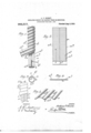
The invention is fully `disclosed in the 'following specification, o't'cvhch the accom panying dra wing` forins a part,iin which the separate parts ofiny improvement are des? ignated by suitableV reference clniracterslin each ot` the views and in which2- Figurel .is a` perspective v1e\v showingr in v in'iproved electric conduit and showing" u V the niethod of its construction; 141g'. 2 a
plan and cud view of a strip of fibrous inaterial which l employ' in the construction of iny improved electric conduit; rFig. 3 an end view of atube formed troni the fibrous strip shown in Fig'. 2, said tube being also shown in Fig. l; Fig; fl a partial section on the line Ll-fl of Fig. 2; Fig. 5 a perspective view of a iiictal strip or strips which, in practice, are wound Von the fibrous 'tube shown iii Figs. 2 and 3, said strip or strips and the inethod of their windingou the .fibrous tube beingalso shown in Fig; l, and Fig. (i a. view similar to Fig. 1` b ut showing a` modification.
, ln the practice of my invention I provide a strip cot tibrous `material, said strip be-` ing composed ot'papei.' pulp or similar inaterial.` or said strip may be composed of pasteboard or a thick heavypaper, and said `strip may be-of aiiyidesred length, andthe i' airrnoirr 1?: einsamer nnooiitifiv; nnwfrczaa. 1 "Instinafrinelconnorirony-sinonimo `,Wiens oa coiinUcToRs;
' i accom- Specification of Letterslatentl l Patented ilfr: `$9., 1910.. Vapplication. rilea If'elnriuanryV 1,1310", Serial No. 541,222. i
v tudinally a tube of a1-1y desired transverse I diniei'isioiis.` u'llie strip ainay bet'roin a sixteenth of an inch to an eighth ot' aninch in thickness according to the size of thetube be `.torn'ied therefrom, and in practice the `oi'iter side of said strip, or tlieside`ivlich `fouine ,the outer side of the tubeyis corru-V `gated` transversely as shown at zgto form corresponding transverse grooves i3 the object of `which is ,to render the `coii'ipleted tube or conduit Hcxihleand elastic.
The transverse corrugations a2 do not, in ,the torin ot 'construction shown, extend entirely across thefstrip o but terminate adjacent' to' the opposite side edgesthereof so as to' torni narrow` strips a* which are not :cormigrated transversely, and when the strip a folded longitudinally to t'orin thetube I) tleedge portions a4 `which are not corrugated transversely `form `a longitudinal Y groove bf" inthe outer surface of said tube,Y at the point where thesi-de edges thereof are brought together, and in this` groove is placed a: narrow strip cofrubber or fibrous material saturated with an insulating and preservative compound, and the tube Z) is also treated in asimilar manner, and ,the `coniplete tubewhen so formed is thus rende'ied `iml'iervions to water or other liquid substances and is niade water and air tight. The material employed for saturating the tube o or the strips o and c, when the latter lis coiiipossed ot'itbrous material, so as to render the saine impervious to moisture or liquids and; at the saine time to give said conduit or tube the requisite insulatin qualities niay consist of any 'of the liquid conipositioris `now useclfor this purprrse` and the application iand use ofwhich are well known. 4 i
After thc tube o has been formed and ref pared iu the manner described l p ace thereon, in the nia/nner shown in Fig. 1, a' flexible and elastic casing or covering al composed, in the :torni of construction shown, of: two narrow strips d2 of metal placed together as shown in Fig. 5 and4 Wound `on the tube o in spiral form, this` operation being performed by means of suitable machinery or by handildesired. The metal strips d2 are bent or curved lon gitudnally so Vas to form, in cross section, a curve which is substantially similar to an oiayee curve and in practice two of said strips;Y are placed together so that the edge of one"` overlaps the edge of theother and a narrow strip e of rubber, or fibrous material, treated with an insulating and preservative compound is placed between the overlapping edges of said stri-ps and when the said strips are wound on the tube b in the manner shown and described they form a eXible metallic casing for said. tube, and together with said tube form a flexible conduit for the purpose specified, the casing d of which is water and air tight.
Although I prefer vto place two of the strips d2 together in forming the casing d of the tube b as shown and described it will be apparent that a single metal strip Z2 may be employed for this purpose as shown in F ig. (i of the drawing, said strip being curved in transverse section` and the edges thereof overlapped and' interlocked when helically wound on the tube.v b in such manner as to render said conduit freely flexible at all points.
In the form of construction shown theclaim, without departing from the spirit of my invention di' sacrificing its advantages.
Having fully described my invention what l claim as new,and desire to secure by Letters Patent, is g A flexible tubular conduit for electric wires or conductors'composed of an inner fibrous tube formed by folding a strip 0f fibrous material so that the side edges thereoi abut, said strip of fibrous material being edges, the said side edges where they abut being overlapped by a narrow strip of tibrousinaterlal' which closes and seals the space between said edges, the said tube of fibrous material being inclosed by a helically wyound 'metal strip curved in cross section so that one edge of Said strip overlaps the other and a fibrous strip placed between tsaid overlapping edges, all of said fibrous parts being treated so as to render them impervious .to moisture or liquids and so as to render said conduit water-tight.
In testimony that I claim the foregoing as my invention I have signed my name in presence of the subscribing witnesses this 29th day of January 1910.
ANTHONY PJHINsKY.
corrugated at an angle to its opposite side
Priority Applications (1)
| Application Number | Priority Date | Filing Date | Title |
|---|---|---|---|
| US54122210A US966917A (en) | 1910-02-01 | 1910-02-01 | Insulating-conduit for electric wires or conductors. |
Applications Claiming Priority (1)
| Application Number | Priority Date | Filing Date | Title |
|---|---|---|---|
| US54122210A US966917A (en) | 1910-02-01 | 1910-02-01 | Insulating-conduit for electric wires or conductors. |
Publications (1)
| Publication Number | Publication Date |
|---|---|
| US966917A true US966917A (en) | 1910-08-09 |
Family
ID=3035309
Family Applications (1)
| Application Number | Title | Priority Date | Filing Date |
|---|---|---|---|
| US54122210A Expired - Lifetime US966917A (en) | 1910-02-01 | 1910-02-01 | Insulating-conduit for electric wires or conductors. |
Country Status (1)
| Country | Link |
|---|---|
| US (1) | US966917A (en) |
-
1910
- 1910-02-01 US US54122210A patent/US966917A/en not_active Expired - Lifetime
Similar Documents
| Publication | Publication Date | Title |
|---|---|---|
| US2043044A (en) | Electric cable | |
| US753461A (en) | Electrical conductor and coil | |
| US463107A (en) | Sylvania | |
| US3836181A (en) | Cleat for joining duct work | |
| US2040383A (en) | Means for joining electric current conductors | |
| US479525A (en) | Frederic a | |
| US1827035A (en) | Insulating jacket | |
| KR870006689A (en) | Gas Discharge Surge Voltage Protector | |
| US967260A (en) | Spiral metallic hose. | |
| US1585124A (en) | Cable joint | |
| US1622032A (en) | Electrical conduit | |
| US1939451A (en) | Flexible metallic conduit | |
| GB191005048A (en) | Insulating Conduits for Electric Wires or Conductors. | |
| US1095648A (en) | Armored conduit or conductor. | |
| US475920A (en) | Electric conductor | |
| US778666A (en) | Flexible conduit. | |
| US1022943A (en) | Conduit. | |
| US2331116A (en) | Flexible hollow conductor | |
| US996515A (en) | Flexible protector for electric cables and like purposes. | |
| USRE26273E (en) | Pipe wrapping | |
| US956186A (en) | Armored electric conductor. | |
| GB1459579A (en) | Heat-generating pipe utilizing skin effect current having an insulated wire provided with a divided corona shield layer | |
| US456271A (en) | Flexible conduit for electric conductors | |
| GB517225A (en) | Improvements relating to electric cables and other electrical conductors | |
| US916741A (en) | Armored conductor. |