US9664014B2 - Method and system for segmental flow control in oil-gas well - Google Patents
Method and system for segmental flow control in oil-gas well Download PDFInfo
- Publication number
- US9664014B2 US9664014B2 US13/514,743 US201013514743A US9664014B2 US 9664014 B2 US9664014 B2 US 9664014B2 US 201013514743 A US201013514743 A US 201013514743A US 9664014 B2 US9664014 B2 US 9664014B2
- Authority
- US
- United States
- Prior art keywords
- annular space
- flow control
- particles
- channeling
- perforated pipe
- Prior art date
- Legal status (The legal status is an assumption and is not a legal conclusion. Google has not performed a legal analysis and makes no representation as to the accuracy of the status listed.)
- Active, expires
Links
Images


Classifications
-
- E—FIXED CONSTRUCTIONS
- E21—EARTH OR ROCK DRILLING; MINING
- E21B—EARTH OR ROCK DRILLING; OBTAINING OIL, GAS, WATER, SOLUBLE OR MELTABLE MATERIALS OR A SLURRY OF MINERALS FROM WELLS
- E21B43/00—Methods or apparatus for obtaining oil, gas, water, soluble or meltable materials or a slurry of minerals from wells
- E21B43/12—Methods or apparatus for controlling the flow of the obtained fluid to or in wells
-
- E—FIXED CONSTRUCTIONS
- E21—EARTH OR ROCK DRILLING; MINING
- E21B—EARTH OR ROCK DRILLING; OBTAINING OIL, GAS, WATER, SOLUBLE OR MELTABLE MATERIALS OR A SLURRY OF MINERALS FROM WELLS
- E21B43/00—Methods or apparatus for obtaining oil, gas, water, soluble or meltable materials or a slurry of minerals from wells
- E21B43/14—Obtaining from a multiple-zone well
Definitions
- the present application relates to a flow control method in an oil-gas well exploitation field, and in particular to a sectional flow control method using a flow control filter string in an oil-gas well having a perforated pipe.
- An oil-gas well generally refers to a production well in the oil-gas field development in a broad sense, including an oil well, a gas well, an injection well and so on.
- the oil-gas well In the production process of the oil-gas well, due to the heterogeneous characteristic of the oil reservoir, the oil-gas well, regardless of a vertical well or a horizontal well, has to be sealed off and separated into multiple independent zones for production.
- the oil-gas well production mentioned herein includes the production and injection of the fluid in the oil-gas well production process, for example, injecting water and vapor into the formation in the petroleum exploitation or production process, and injecting chemical agents for improving the oil field recovery ratio, and also includes the injection of acid liquor into the formation in some operation processes, etc.
- a device for controlling flow rate in sections for example, a flow control filter string
- a device for separating the production section of the oil-gas well into several flow units along the axial direction of the oil-gas well for example, a packer
- FIG. 1 is a schematic view illustrating the flow control by using a flow control filter string and a packer in an open hole.
- reference numeral 1 indicates a borehole wall of the oil-gas well
- reference numeral 2 indicates a flow control filter string
- reference numeral 3 indicates an annular space between the flow control filter string and the borehole wall
- reference numeral 4 indicates a packer hung with the flow control filter string
- reference numeral 5 indicates a flow control packer.
- FIG. 1 shows a non-oil-bearing formation, an oil-bearing formation and bottom water under the oil-bearing formation.
- Various formations are schematically indicated by horizontal lines in FIG. 1 , though the person skilled in the art may understand that these formations may not be horizontal, which depends on the geologic structure of the locality where the oil-gas well is located.
- the oil-gas well as shown in the figure includes a vertical section and a horizontal section.
- the horizontal section substantially extends along the oil-bearing formation so as to increase the contact area between the borehole wall and the oil-bearing formation.
- FIG. 1 illustratively shows two zones having different permeability, i.e.
- a high permeability zone and a low permeability zone Under the situation without flow control in the oil-gas well (i.e. no packer 5 is provided in FIG. 1 ), since the permeability of the two zones is different, a flow rate of the fluid in the high permeability zone is larger than a flow rate of the fluid in the low permeability zone. In this case, due to the difference between the pressure of the bottom water and the pressure inside the oil-gas well, the bottom water under the oil-bearing formation may firstly pass through the high permeability zone and enter into the oil-gas well, which may cause the decrease of oil and gas and the increase of water in the production of the oil-gas well. This should be avoided in the production.
- the sectional flow-rate control production in many oil-gas wells is realized as follows.
- a flow control filter string 2 is lowered into the production section inside the oil-gas well, and the flow control filter string 2 and the packer 5 are used to effectively seal off and partition an annular space between the flow control filter string 2 and the production section inside the oil-gas well, i.e. axial channeling passage of fluid outside the flow control filter string is blocked, thereby realizing a better sectional flow-rate control production.
- the packer is provided between two zones having different permeability.
- the packer Since the flow control filter can play a role of flow-rate control, the packer is used to pack off the zones having different permeability so as to perform independent control or sectional control of various zones having different permeability. Therefore, it is possible for the oil-gas well to achieve a good production, and to effectively control the quantity of the bottom water entering into the oil-gas well.
- the current well completion of the oil-gas well is achieved by running a perforated pipe into an open hole, and an annular space between the perforated pipe and the open hole wall is not sealed by filling cement or other materials between the perforated pipe and the borehole wall.
- the well completion method has an advantage of the low cost, and a disadvantage that the annular space becomes a passage for fluid channeling, so that it is difficult to realize the sectional flow control in the later production.
- Each meter of the perforated pipe is provided with several to dozens of holes with a diameter about 10 mm.
- the perforated pipe is mainly used in the oil-gas well to support the borehole wall and prevent lumps in the well from entering into the perforated pipe so as to ensure that the whole flow passage of the oil-gas well is not blocked by lumps.
- reference numeral 11 indicates a borehole wall of the oil-gas well
- reference numeral 12 indicates a perforated pipe
- reference numeral 13 indicates an annular space between the perforated pipe and the borehole wall
- reference numeral 14 indicates a packer hung with the perforated pipe
- reference numeral 15 indicates a flow control filter string
- reference numeral 16 indicates a flow control filter on the flow control filter string
- reference numeral 17 indicates a packer provided in the annular space between the flow control filter string and the perforated pipe
- reference numeral 18 indicates a packer hung with the flow control filter string.
- a direction of arrows in the figure indicates the fluid channeling direction. As shown in FIG.
- the fluid in the formation passes through the borehole wall and enters into the annular space between the borehole wall and the perforated pipe, so that the axial channeling is formed in the annular space between the borehole wall and the perforated pipe, and then passes through the flow control filter and enters into the flow control filter string.
- This axial channeling destroys the pack-off effect of the packer provided between the flow control filter string and the perforated pipe, thus a good water control effect can not be realized.
- a technical problem to be solved by the present application is to provide a sectional flow control method using a flow control filter string in an oil-gas well having a perforated pipe, in which the annular space between the flow control filter string and the perforated pipe and the annular space between the perforated pipe and the borehole wall are filled with anti-channeling pack-off particles, so as to realize a good pack-off effect, thereby realizing a good sectional flow control production.
- one embodiment of the present application provides a sectional flow control method in an oil-gas well, wherein the oil-gas well includes a first annular space formed between a borehole wall of the oil-gas well and a perforated pipe, and a second annular space formed between the perforated pipe and a flow control filter string.
- the perforated pipe is located inside the oil-gas well and extends along an axial direction of the oil-gas well.
- the flow control filter string is located inside the perforated pipe and extends along the axial direction of the oil-gas well.
- the method includes the step of: filling anti-channeling pack-off particles into the first annular space and the second annular space such that fluid can flow in a penetration manner in the first annular space and the second annular space filled with the anti-channeling pack-off particles.
- filling the anti-channeling pack-off particles into the first annular space and the second annular space is performed by injecting particle-carrying fluid with the anti-channeling pack-off particles into the first annular space and the second annular space.
- the particle-carrying fluid has a density substantially equal to a density of the anti-channeling pack-off particles.
- the particle-carrying fluid is water or aqueous solution.
- the anti-channeling pack-off particles are high molecular polymer particles with an average particle size ranging from 0.05 mm to 1.0 mm and a density ranging from 0.8 g/cm 3 to 1.4 g/cm 3 .
- the anti-channeling pack-off particles are high molecular polymer particles with an average particle size ranging from 0.1 mm to 0.5 mm and a density ranging from 0.94 g/cm 3 to 1.06 g/cm 3 .
- the anti-channeling pack-off particles are high-density polyethylene particles with an average particle size ranging from 0.1 mm to 0.05 mm and a density ranging from 0.90 g/cm 3 to 0.98 g/cm 3 .
- the anti-channeling pack-off particles are styrene and divinylbenzene crosslinking copolymer particles with an average particle size ranging from 0.05 mm to 1.0 mm and a density ranging from 0.96 g/cm 3 to 1.06 g/cm 3 .
- the anti-channeling pack-off particles are polypropylene and polyvinyl chloride high molecular polymer particles with an average particle size ranging from 0.05 mm to 1.0 mm and a density ranging from 0.8 g/cm 3 to 1.2 g/cm 3 .
- the anti-channeling pack-off particles are filled into the first annular space and the second annular space until the first annular space and the second annular space are substantially full of the anti-channeling pack-off particles, and the first annular space and the second annular space are closed.
- the oil-gas well is a horizontal well or an inclined well.
- a difference between a density of the particle-carrying fluid and a density of the anti-channeling pack-off particles is within a range of ⁇ 0.4 g/cm 3 or a range of ⁇ 0.2 g/cm 3 .
- a sectional flow control system for an oil-gas well including: a first annular space formed between a borehole wall of the oil-gas well and a perforated pipe; a second annular space formed between the perforated pipe and a flow control filter string; and anti-channeling pack-off particles.
- the perforated pipe is located inside the oil-gas well and extends along an axial direction of the oil-gas well.
- the flow control filter string is located inside the perforated pipe and extends along the axial direction of the oil-gas well.
- the anti-channeling pack-off particles are filled in the first annular space and the second annular space such that fluid can flow in a penetration manner in the first annular space and the second annular space filled with the anti-channeling pack-off particles.
- the first annular space and the second annular space are filled by injecting particle-carrying fluid with the anti-channeling pack-off particles into the first annular space and the second annular space.
- the particle-carrying fluid has a density substantially equal to a density of the anti-channeling pack-off particles.
- the particle-carrying fluid is water or aqueous solution.
- the anti-channeling pack-off particles are high molecular polymer particles with an average particle size ranging from 0.05 mm to 1.0 mm and a density ranging from 0.8 g/cm 3 to 1.4 g/cm 3 .
- the anti-channeling pack-off particles are high molecular polymer particles with an average particle size ranging from 0.1 mm to 0.5 mm and a density ranging from 0.94 g/cm 3 to 1.06 g/cm 3 .
- the anti-channeling pack-off particles are high-density polyethylene particles with an average particle size ranging from 0.1 mm to 0.5 mm and a density ranging from 0.90 g/cm 3 to 0.98 g/cm 3 .
- the anti-channeling pack-off particles are styrene and divinylbenzene crosslinking copolymer particles with an average particle size ranging from 0.05 mm to 1.0 mm and a density ranging from 0.96 g/cm 3 to 1.06 g/cm 3 .
- the anti-channeling pack-off particles are polypropylene and polyvinyl chloride high molecular polymer particles with an average particle size ranging from 0.05 mm to 1.0 mm and a density ranging from 0.8 g/cm 3 to 1.2 g/cm 3 .
- the first annular space and the second annular space are substantially full of the anti-channeling pack-off particles, and are closed.
- the oil-gas well is a horizontal well or an inclined well.
- a difference between the density of the particle-carrying fluid and the density of the anti-channeling pack-off particles is within a range of ⁇ 0.4 g/cm 3 or a range of ⁇ 0.2 g/cm 3 .
- a sectional flow control method using a flow control filter string in an oil-gas well having a perforated pipe wherein the oil-gas well having the perforated pipe includes a borehole wall of the oil-gas well and the perforated pipe running in the oil-gas well, one end of the perforated pipe adjacent to a wellhead is fixedly connected to the borehole wall, and an annular space is formed between the perforated pipe and the borehole wall.
- the sectional flow control method using a flow control filter string includes the following steps:
- the particle density mentioned in the present application is the true density of the individual particles, rather than the packing density of the particles.
- the present application uses water or aqueous solution with a density about 1 g/cm 3 as the particle-carrying fluid to carry anti-channeling pack-off particles, and the present application uses anti-channeling pack-off particles having almost the same density as the particle-carrying fluid, thus the particle-carrying fluid may easily carry the anti-channeling pack-off particles to fill in the annular space between the flow control filter string and the perforated pipe and the annular space between the perforated pipe and the borehole wall.
- the anti-channeling pack-off particles are accumulated both in the annular space between the flow control filter string and the perforated pipe and in the annular space between the perforated pipe and the borehole wall, so that the annular space between the flow control filter string and the perforated pipe and the annular space between the perforated pipe and the borehole wall are filled with and full of the anti-channeling pack-off particles.
- a part of the particle-carrying fluid enters into the flow control filter and then flows back to the ground, and another part of the particle-carrying fluid passes through the borehole wall and penetrates into the formation.
- a well completion structure is formed, in which the annular space between the flow control filter string and the perforated pipe and the annular space between the perforated pipe and the borehole wall are filled with the anti-channeling pack-off particles.
- the anti-channeling pack-off particles are filled tightly and there is almost no channeling.
- the oil-gas well may effectively be sealed off and separated into multiple independent zones with combination of the flow control filter string, so as to perform oil-gas well production, realize the object of flow control, and facilitate the flow-rate sectional management, thereby bringing good effects of the oil-gas well production, for example, improving the production efficiency of the oil-gas well.
- the formation fluid flows in media formed by the accumulation of the anti-channeling pack-off particles in the penetration manner.
- the penetration resistance is proportional to the penetration distance, and is inversely proportional to the penetration area.
- the accumulation body of the anti-channeling pack-off particles has a thin thickness, a small section and a long axial length. Accordingly, a channeling resistance of the formation fluid flowing in the anti-channeling pack-off particles along the axial direction of the oil-gas well is very high.
- the penetration area is big and the penetration distance is short, thus the flow resistance is very small.
- the resistance flowing in the accumulation body for several meters or tens of meters along the axial direction of the oil-gas well is hundreds times even thousands times more than the resistance flowing in the accumulation body for several centimeters along the radial direction of the oil-gas well. Due to the great difference between the resistance flowing in the accumulation body along the axial direction of the oil-gas well and the resistance flowing in the accumulation body along the radial direction of the oil-gas well, the flow rate flowing in the accumulation body along the axial direction of the oil-gas well is far less than the flow rate flowing in the accumulation body along the radial direction of the oil-gas well under the same pressure difference.
- the smooth flow of the formation fluid in the accumulation body along the radial direction of the oil-gas well may be ensured, and the flow of the formation fluid along the axial direction of the oil-gas well may be limited, thereby functioning as a packer.
- the present application provides a convenient and useful sectional flow control method using a flow control filter string in an oil-gas well having a perforated pipe, which may pack off the annular space between the flow control filter string and the perforated pipe and the annular space between the perforated pipe and the borehole wall, thereby having a good pack-off effect, realizing the sectional flow control production well, and satisfying the actual production requirements of the oil field, for example, improving the oil recovery ratio.
- FIG. 1 is a schematic view illustrating the flow control by using a flow control filter string and a packer in an open hole in the prior art
- FIG. 2 is a schematic view of a hypothetical state where the flow control technology using the flow control filter string and the packer as shown in FIG. 1 is applied to an oil-gas well having a perforated pipe, the flow control filter string is lowered into the perforated pipe, an annular space between the flow control filter string and the perforated pipe is packed off, while an annular space between the perforated pipe and a borehole wall is not packed off;
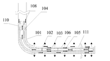
- FIG. 3 is a schematic view of a sectional flow control method using a flow control filter string in an oil-gas well having a perforated pipe according to an embodiment of the present application.
- FIG. 4 is a schematic view of a well completion structure according to an embodiment of the present application, in which an annular space between the flow control filter string and the perforated pipe and an annular space between the perforated pipe and a borehole wall are both filled with anti-channeling pack-off particles.
- the present application provides a sectional flow control method using a flow control filter string in an oil-gas well having a perforated pipe.
- the oil-gas well having the perforated pipe therein includes a borehole wall of the oil-gas well and the perforated pipe running into the oil-gas well.
- One end of the perforated pipe adjacent to a wellhead is fixedly connected to the borehole wall, and an annular space is formed between the perforated pipe and the borehole wall.
- the sectional flow control method using the flow control filter string includes the following steps:
- the particle-carrying fluid carrying the anti-channeling pack-off particles is water or aqueous solution.
- the anti-channeling pack-off particles may be high molecular polymer particles with a particle size ranging from 0.05 mm to 0.7 mm and a density ranging from 0.8 g/cm 3 to 1.2 g/cm 3 .
- the anti-channeling pack-off particles may be high molecular polymer particles with an average particle size ranging from 0.05 mm to 1.0 mm and a density ranging from 0.8 g/cm 3 to 1.4 g/cm 3 .
- the anti-channeling pack-off particles may be high molecular polymer particles with an average particle size ranging from 0.1 mm to 0.5 mm and a density ranging from 0.94 g/cm 3 to 1.06 g/cm 3 .
- the anti-channeling pack-off particles may be high-density polyethylene particles with an average particle size ranging from 0.1 mm to 0.5 mm and a density ranging from 0.90 g/cm 3 to 0.98 g/cm 3 .
- the anti-channeling pack-off particles may be styrene and divinylbenzene crosslinking copolymer particles with an average particle size ranging from 0.05 mm to 1.0 mm and a density ranging from 0.96 g/cm 3 to 1.06 g/cm 3 .
- the anti-channeling pack-off particles may be polypropylene and polyvinyl chloride high molecular polymer particles with an average particle size ranging from 0.05 mm to 1.0 mm and a density ranging from 0.8 g/cm 3 to 1.2 g/cm 3 .
- the embodiment of the present application provides a sectional flow control method using a flow control filter string in an oil-gas well having a perforated pipe.
- the oil-gas well structure having the perforated pipe includes a borehole wall 101 of the oil-gas well and a perforated pipe 102 running in the oil-gas well.
- Each meter of the perforated pipe 102 is provided with multiple small holes. For example, the number of the small holes is 30 .
- the diameter of the small holes is configured to be able to prevent lumps from entering into the perforated pipe 102 , for example 10 mm.
- a packer 104 hung with the perforated pipe 102 is provided between an upper portion of the perforated pipe 102 and the borehole wall 101 .
- An annular space 103 is formed between the perforated pipe 102 and the borehole wall 101 .
- a flow control filter string 105 is run into the perforated pipe 102 via a running string (not shown).
- a flow control filter 106 is provided on the flow control filter string 105 .
- a packer 108 hung with the flow control filter string 105 is provided between an upper portion of the flow control filter string 105 and the borehole wall 101 .
- An annular space 103 is formed between the flow control filter string 105 and the perforated pipe 102 .
- a particle-carrying fluid 110 carrying the anti-channeling pack-off particles is injected into the annular space 103 between the flow control filter string 105 and the perforated pipe 102 .
- the particle-carrying fluid 110 carrying the anti-channeling pack-off particles passes through small holes in the perforated pipe 102 and enters into the annular space 111 between the perforated pipe 102 and the borehole wall 101 .
- the anti-channeling pack-off particles are accumulated both in the annular space 103 between the flow control filter string 105 and the perforated pipe 102 and in the annular space 111 between the perforated pipe 102 and the borehole wall 101 , so that the annular space 103 between the flow control filter string 105 and the perforated pipe 102 and the annular space 111 between the perforated pipe 102 and the borehole wall 101 are filled with and full of the anti-channeling pack-off particles.
- a part of the particle-carrying fluid penetrates through the flow control filter 106 and enters into the flow control filter string 105 and then flows back to the ground, and another part of the particle-carrying fluid passes through the borehole wall 101 and penetrates into the formation.
- the direction of arrows in FIG. 3 is the flowing direction of the particle-carrying fluid.
- the anti-channeling pack-off particles are high-density polyethylene particles with an average particle size ranging from 0.1 mm to 0.5 mm and a density ranging from 0.90 g/cm 3 to 0.98 g/cm 3 .
- the particle-carrying fluid is water.
- the packer 108 hung with the flow control filter string 105 is set so as to close both the annular space 103 between the flow control filter string 105 and the perforated pipe 102 and the annular space 111 between the perforated pipe 102 and the borehole wall 101 which are filled with the anti-channeling pack-off particles.
- the running string (not shown) connected to the flow control filter string 105 is disengaged and a well completion structure is formed.
- the annular space 103 between the flow control filter string 105 and the perforated pipe 102 and the annular space 111 between the perforated pipe 102 and the borehole wall 101 are filled with the anti-channeling pack-off particles, as shown in FIG. 4 .
- FIG. 4 In FIG.
- reference numeral 101 indicates the borehole wall of the oil-gas well
- reference numeral 102 indicates the perforated pipe
- reference numeral 104 indicates the packer hung with the perforated pipe
- reference numeral 105 indicates the flow control filter string
- reference numeral 106 indicates the flow control filter on the flow control filter string
- reference numeral 107 indicates the anti-channeling pack-off particles filled the annular space between the flow control filter string and the perforated pipe
- reference numeral 108 indicates the packer hung with the flow control filter string
- reference numeral 109 indicates the anti-channeling pack-off particles filled the annular space between the perforated pipe and the borehole wall.
- the anti-channeling pack-off particles are polypropylene and polyvinyl chloride high molecular polymer particles with an average particle size ranging from 0.1 mm to 0.5 mm and a density being 0.97 g/cm 3 .
- the anti-channeling pack-off particles are styrene and divinylbenzene crosslinking copolymer particles with an average particle size ranging from 0.05 mm to 1.0 mm and a density ranging from 0.96 g/cm 3 to 1.06 g/cm 3 .
- water is used to carry the anti-channeling pack-off particles.
- the density of water is 1 g/cm 3 .
- the density of the anti-channeling pack-off particles selected in the present application is almost the same as the density of water. Therefore, the water may easily carry the anti-channeling pack-off particles to fill in the annular space 103 between the flow control filter string 105 and the perforated pipe 102 and the annular space 111 between the perforated pipe 102 and the borehole wall 101 .
- the anti-channeling pack-off particles are accumulated both in the annular space 103 between the flow control filter string 105 and the perforated pipe 102 and in the annular space 111 between the perforated pipe 102 and the borehole wall 101 , so that the annular space 103 between the flow control filter string 105 and the perforated pipe 102 and the annular space 111 between the perforated pipe 102 and the borehole wall 101 are filled with and full of the anti-channeling pack-off particles.
- a part of the water passes through the flow control filter 106 and enters into the flow control filter string 105 and then flows back to the ground, and another part of the water passes through the borehole wall 101 and penetrates into the formation.
- annular space 103 between the flow control filter string 105 and the perforated pipe 102 and the annular space 111 between the perforated pipe 102 and the borehole wall 101 are filled with the anti-channeling pack-off particles.
- the formation fluid flows in media formed by the accumulation of the anti-channeling pack-off particles in a penetration manner.
- the penetration resistance is proportional to the penetration distance, and is inversely proportional to the penetration area.
- the accumulation body of the anti-channeling pack-off particles is a medium having a thin thickness, a small section and a long axial length, thus the channeling resistance of the formation fluid flowing in the accumulation body of the anti-channeling pack-off particles along the axial direction of the oil-gas well is very high.
- the penetration area is big and the penetration distance is short, thus the flow resistance is very small.
- the resistance flowing in the accumulation body for several meters or tens of meters along the axial direction of the oil-gas well is hundreds times even thousands times more than the resistance flowing in the accumulation body for several centimeters along the radial direction of the oil-gas well. Due to the great difference between the resistance flowing in the accumulation body along the axial direction of the oil-gas well and the resistance flowing in the accumulation body along the radial direction of the oil-gas well, the flow rate flowing in the accumulation body along the axial direction of the oil-gas well is far less than the flow rate flowing in the accumulation body along the radial direction of the oil-gas well under the same pressure difference.
- the smooth flow of the formation fluid in the accumulation body along the radial direction of the oil-gas well may be ensured, and the flow of the formation fluid along the axial direction of the oil-gas well may be limited, thereby functioning as a packer.
- the present application provides a convenient and useful sectional flow control method in an oil-gas well having a perforated pipe, which may pack off both the annular space between the flow control filter string and the perforated pipe and the annular space between the perforated pipe and the borehole wall.
- the sectional flow control production may be realized due to the good pack-off effect, so as to improve the oil recovery ratio and satisfy the actual production requirements of the oil field.
- the production section referred in the present application is a generalized production section. There may be some non-flowing sections (for example, an interlayer, a sandwich layer and an imperforated interval after the casing cementing) along the length of the production section.
- non-flowing sections for example, an interlayer, a sandwich layer and an imperforated interval after the casing cementing
- the flow control filter string in the present application includes filtering sections and blank sections which are arranged alternately.
- the blank section is a pipe without holes on its wall surface.
- the anti-channeling pack-off particle ring outside the blank sections plays a major role in preventing the axial channeling.
- the blank sections are provided in two ways.
- each filter itself includes a filtering section and blank sections provided at two ends of the filter and provided with screw threads, so that two filters may be connected via the screw threads on the blank sections of the two filters.
- the blank section is a place for setting the pliers.
- an additional blank section may be connected between two filters. Under the situation that a relatively long flow control filter string is desired, the flow control filter string may be formed by connecting multiple flow control filters in series.
- the anti-channeling pack-off particles in the present application is preferably circular.
- a sectional flow control method using a flow control filter string in an oil-gas well having a perforated pipe wherein the oil-gas well having the perforated pipe includes a borehole wall of the oil-gas well and the perforated pipe running into the oil-gas well, one end of the perforated pipe adjacent to a wellhead is fixedly connected to the borehole wall, and an annular space is formed between the perforated pipe and the borehole wall.
- the particle-carrying fluid carrying the anti-channeling pack-off particles is water or aqueous solution.
- the anti-channeling pack-off particles may be high molecular polymer particles with an average particle size ranging from 0.05 mm to 1.0 mm and a density ranging from 0.8 g/cm 3 to 1.4 g/cm 3 .
- the anti-channeling pack-off particles may be high molecular polymer particles with an average particle size ranging from 0.1 mm to 0.5 mm and a density ranging from 0.94 g/cm 3 to 1.06 g/cm 3 .
- the anti-channeling pack-off particles may be high-density polyethylene particles with an average particle size ranging from 0.1 mm to 0.5 mm and a density ranging from 0.90 g/cm 3 to 0.98 g/cm 3 .
- the anti-channeling pack-off particles may be styrene and divinylbenzene crosslinking copolymer particles with an average particle size ranging from 0.05 mm to 1.0 mm and a density ranging from 0.96 g/cm 3 to 1.06 g/cm 3 .
- the anti-channeling pack-off particles may be polypropylene and polyvinyl chloride high molecular polymer particles with an average particle size ranging from 0.05 mm to 1.0 mm and a density ranging from 0.8 g/cm 3 to 1.2 g/cm 3 .
Landscapes
- Life Sciences & Earth Sciences (AREA)
- Engineering & Computer Science (AREA)
- Geology (AREA)
- Mining & Mineral Resources (AREA)
- Physics & Mathematics (AREA)
- Environmental & Geological Engineering (AREA)
- Fluid Mechanics (AREA)
- General Life Sciences & Earth Sciences (AREA)
- Geochemistry & Mineralogy (AREA)
- Filtering Materials (AREA)
- Treatment Of Liquids With Adsorbents In General (AREA)
Abstract
Description
Claims (14)
Applications Claiming Priority (4)
| Application Number | Priority Date | Filing Date | Title |
|---|---|---|---|
| CN200910250793 | 2009-12-11 | ||
| CN200910250793.1 | 2009-12-11 | ||
| CN200910250793A CN101705810B (en) | 2009-12-11 | 2009-12-11 | Segmented current controlling method of current controlling filter pipe column of oil-gas well having perforated pipe |
| PCT/CN2010/079550 WO2011069447A1 (en) | 2009-12-11 | 2010-12-08 | Method and system for segmental flow control in oil -gas well |
Publications (2)
| Publication Number | Publication Date |
|---|---|
| US20120241168A1 US20120241168A1 (en) | 2012-09-27 |
| US9664014B2 true US9664014B2 (en) | 2017-05-30 |
Family
ID=42376059
Family Applications (2)
| Application Number | Title | Priority Date | Filing Date |
|---|---|---|---|
| US13/514,743 Active 2033-05-16 US9664014B2 (en) | 2009-12-11 | 2010-12-08 | Method and system for segmental flow control in oil-gas well |
| US13/514,721 Pending US20120318505A1 (en) | 2009-12-11 | 2010-12-08 | Method and system for segmental flow control in oil-gas well |
Family Applications After (1)
| Application Number | Title | Priority Date | Filing Date |
|---|---|---|---|
| US13/514,721 Pending US20120318505A1 (en) | 2009-12-11 | 2010-12-08 | Method and system for segmental flow control in oil-gas well |
Country Status (3)
| Country | Link |
|---|---|
| US (2) | US9664014B2 (en) |
| CN (1) | CN101705810B (en) |
| WO (1) | WO2011069447A1 (en) |
Families Citing this family (16)
| Publication number | Priority date | Publication date | Assignee | Title |
|---|---|---|---|---|
| CN101705802B (en) * | 2009-12-11 | 2013-05-15 | 安东石油技术(集团)有限公司 | Anti-crossflow packing particles for production sections of oil and gas wells |
| CN101705808B (en) * | 2009-12-11 | 2012-05-30 | 安东石油技术(集团)有限公司 | Sectional flow control method for flow control filter pipe column of oil-gas well with bushing outside channel |
| CN101705810B (en) * | 2009-12-11 | 2012-09-05 | 安东石油技术(集团)有限公司 | Segmented current controlling method of current controlling filter pipe column of oil-gas well having perforated pipe |
| RU2488686C1 (en) * | 2012-01-10 | 2013-07-27 | Открытое акционерное общество "Татнефть" имени В.Д. Шашина | Method for separation and control of development of deposits drains with horizontal well, and device for its implementation |
| US10260330B2 (en) | 2015-04-29 | 2019-04-16 | General Electric Company | Fluid intake for an artificial lift system and method of operating such system |
| US20180187533A1 (en) * | 2017-01-05 | 2018-07-05 | Saudi Arabian Oil Company | Hydrocarbon production by fluidically isolating vertical regions of formations |
| EP3695095A4 (en) * | 2017-10-13 | 2021-07-21 | Abu Dhabi National Oil Company | Method and device for producing fluids or gases from a horizontal well |
| CN111949650A (en) | 2019-05-15 | 2020-11-17 | 华为技术有限公司 | Multi-language fusion query method and multi-mode database system |
| CN110173230A (en) * | 2019-06-06 | 2019-08-27 | 安东柏林石油科技(北京)有限公司 | Prevent artificial borehole wall, forming method and the completion structure of shale layer mud output or channelling |
| CN110593862B (en) * | 2019-09-02 | 2020-09-18 | 中国石油大学(北京) | Method, device and computer equipment for determining dominant seepage channel |
| CA3217398A1 (en) | 2021-05-11 | 2022-11-17 | Dragan Stojkovic | Polyolefin-coke composite granules as a hydraulic fracturing proppant |
| CN113833437A (en) * | 2021-09-24 | 2021-12-24 | 安东柏林石油科技(北京)有限公司 | A method and structure for improving axial anti-channeling flow capability in downhole annulus |
| CA3245321A1 (en) | 2022-03-04 | 2023-09-07 | ExxonMobil Technology and Engineering Company | Proppants derived from crosslinking mixed aromatic resins |
| CN117489296B (en) * | 2023-12-29 | 2024-03-22 | 克拉玛依市白碱滩区(克拉玛依高新区)石油工程现场(中试)实验室 | Inter-well channeling prevention method and simulation experiment device |
| US12540273B2 (en) | 2024-01-19 | 2026-02-03 | ExxonMobil Technology and Engineering Company | Proppant particles formed from fluid coke and flexicoke, fracturing fluids comprising such proppant particles, and methods related thereto |
| US12521764B2 (en) | 2024-06-19 | 2026-01-13 | ExxonMobil Technology and Engineering Company | Methods for preparing petroleum coke proppant particles for hydraulic fracturing |
Citations (13)
| Publication number | Priority date | Publication date | Assignee | Title |
|---|---|---|---|---|
| US20020020524A1 (en) | 2000-05-04 | 2002-02-21 | Halliburton Energy Services, Inc. | Expandable liner and associated methods of regulating fluid flow in a well |
| US20030075315A1 (en) * | 1997-10-16 | 2003-04-24 | Nguyen Philip D. | Methods and apparatus for completing wells in unconsolidated subterranean zones |
| WO2005078235A1 (en) | 2004-02-12 | 2005-08-25 | Shell Internationale Research Maatschappij B.V. | Suppressing fluid communication to or from a wellbore |
| CN101238271A (en) | 2005-06-01 | 2008-08-06 | 贝克休斯公司 | expandable flow control device |
| US20080230223A1 (en) * | 2007-03-22 | 2008-09-25 | Hexion Specialty Chemicals, Inc. | Low temperature coated particles for use as proppants or in gravel packs, methods for making and using the same |
| US20090000787A1 (en) | 2007-06-27 | 2009-01-01 | Schlumberger Technology Corporation | Inflow control device |
| CN201254976Y (en) | 2008-09-04 | 2009-06-10 | 安东石油技术(集团)有限公司 | New horizontal well sand prevention well completion structure |
| CN101463719A (en) | 2009-01-21 | 2009-06-24 | 安东石油技术(集团)有限公司 | Flow control device of high-efficiency flow control screen pipe |
| CN101476455A (en) | 2008-01-04 | 2009-07-08 | 安东石油技术(集团)有限公司 | Filling water-control sieve tube and its laying method |
| CN101705810A (en) | 2009-12-11 | 2010-05-12 | 安东石油技术(集团)有限公司 | Segmented current controlling method of current controlling filter pipe column of oil-gas well having perforated pipe |
| CN101705809A (en) | 2009-12-11 | 2010-05-12 | 安东石油技术(集团)有限公司 | Segmented current controlling method of current controlling filter pipe column of oil-gas well having sand control pipe |
| CN101705808A (en) | 2009-12-11 | 2010-05-12 | 安东石油技术(集团)有限公司 | Sectional flow control method for flow control filter pipe column of oil-gas well with bushing outside channel |
| CN101748999B (en) | 2008-12-11 | 2012-09-05 | 安东石油技术(集团)有限公司 | Flow control sieve tube |
-
2009
- 2009-12-11 CN CN200910250793A patent/CN101705810B/en active Active
-
2010
- 2010-12-08 WO PCT/CN2010/079550 patent/WO2011069447A1/en not_active Ceased
- 2010-12-08 US US13/514,743 patent/US9664014B2/en active Active
- 2010-12-08 US US13/514,721 patent/US20120318505A1/en active Pending
Patent Citations (16)
| Publication number | Priority date | Publication date | Assignee | Title |
|---|---|---|---|---|
| US20030075315A1 (en) * | 1997-10-16 | 2003-04-24 | Nguyen Philip D. | Methods and apparatus for completing wells in unconsolidated subterranean zones |
| US20020020524A1 (en) | 2000-05-04 | 2002-02-21 | Halliburton Energy Services, Inc. | Expandable liner and associated methods of regulating fluid flow in a well |
| WO2005078235A1 (en) | 2004-02-12 | 2005-08-25 | Shell Internationale Research Maatschappij B.V. | Suppressing fluid communication to or from a wellbore |
| CN1918361A (en) | 2004-02-12 | 2007-02-21 | 国际壳牌研究有限公司 | Suppressing fluid communication to or from a wellbore |
| CN101238271A (en) | 2005-06-01 | 2008-08-06 | 贝克休斯公司 | expandable flow control device |
| US7413022B2 (en) | 2005-06-01 | 2008-08-19 | Baker Hughes Incorporated | Expandable flow control device |
| US20080230223A1 (en) * | 2007-03-22 | 2008-09-25 | Hexion Specialty Chemicals, Inc. | Low temperature coated particles for use as proppants or in gravel packs, methods for making and using the same |
| US20090000787A1 (en) | 2007-06-27 | 2009-01-01 | Schlumberger Technology Corporation | Inflow control device |
| CN101476455A (en) | 2008-01-04 | 2009-07-08 | 安东石油技术(集团)有限公司 | Filling water-control sieve tube and its laying method |
| CN201254976Y (en) | 2008-09-04 | 2009-06-10 | 安东石油技术(集团)有限公司 | New horizontal well sand prevention well completion structure |
| CN101748999B (en) | 2008-12-11 | 2012-09-05 | 安东石油技术(集团)有限公司 | Flow control sieve tube |
| CN101463719A (en) | 2009-01-21 | 2009-06-24 | 安东石油技术(集团)有限公司 | Flow control device of high-efficiency flow control screen pipe |
| CN101705810A (en) | 2009-12-11 | 2010-05-12 | 安东石油技术(集团)有限公司 | Segmented current controlling method of current controlling filter pipe column of oil-gas well having perforated pipe |
| CN101705809A (en) | 2009-12-11 | 2010-05-12 | 安东石油技术(集团)有限公司 | Segmented current controlling method of current controlling filter pipe column of oil-gas well having sand control pipe |
| CN101705808A (en) | 2009-12-11 | 2010-05-12 | 安东石油技术(集团)有限公司 | Sectional flow control method for flow control filter pipe column of oil-gas well with bushing outside channel |
| WO2011069447A1 (en) | 2009-12-11 | 2011-06-16 | 安东石油技术(集团)有限公司 | Method and system for segmental flow control in oil -gas well |
Non-Patent Citations (1)
| Title |
|---|
| For the American Heritage Dictionary definition: control. (n.d.) American Heritage® Dictionary of the English Language, Fifth Edition. (2011). Retrieved Feb. 19, 2016 from http://www.thefreedictionary.com/control. * |
Also Published As
| Publication number | Publication date |
|---|---|
| US20120241168A1 (en) | 2012-09-27 |
| CN101705810A (en) | 2010-05-12 |
| CN101705810B (en) | 2012-09-05 |
| WO2011069447A1 (en) | 2011-06-16 |
| US20120318505A1 (en) | 2012-12-20 |
Similar Documents
| Publication | Publication Date | Title |
|---|---|---|
| US9664014B2 (en) | Method and system for segmental flow control in oil-gas well | |
| US9022110B2 (en) | Segmental flow-control method for flow-control filter string in oil-gas well and oil-gas well structure | |
| US9151142B2 (en) | Segmental flow control method and apparatus for a flow control filter string in an oil-gas well | |
| CN101421486B (en) | Wellbore methods and apparatus for sand control and inflow control during well operations | |
| AU2012321258B2 (en) | Fluid filtering device for a wellbore and method for completing a wellbore | |
| WO2011069339A1 (en) | Isolating particles for preventing channeling in production section of oil-gas well, completion method and production method using the same | |
| CN103688015A (en) | Wellbore apparatus and methods for multi-zone well completion, production and injection | |
| CN110242264B (en) | Packing method and well completion structure for same-well injection and production | |
| US10487630B2 (en) | High flow injection screen system with sleeves | |
| CN207122305U (en) | The oil gas well completion structure of decreasing water cut and increasing oil ability can be improved | |
| CN108060915B (en) | Completion structure capable of improving dewatering and oil increasing capacity | |
| CN104948149B (en) | A kind of multimedium dispensing system suitable in mining site complexity oil reservoir | |
| CN210685949U (en) | Well completion structure for injection and production in same well | |
| CN115030697A (en) | Method of operating a water injection well and water injection well | |
| CN113803050A (en) | Self-adaptive inflow control device, intelligent well completion pipe string and well completion method | |
| CN110173230A (en) | Prevent artificial borehole wall, forming method and the completion structure of shale layer mud output or channelling | |
| CN103867181B (en) | The method for carrying out sectional flow control using excluder ring is partly oozed | |
| AU2015284363B2 (en) | Injector fill displacement tubes |
Legal Events
| Date | Code | Title | Description |
|---|---|---|---|
| AS | Assignment |
Owner name: ANTON OILFIELD SERVICES (GROUP) LTD., CHINA Free format text: ASSIGNMENT OF ASSIGNORS INTEREST;ASSIGNORS:PEI, BAILIN;XUE, YONG;ZHANG, SONGMEI;REEL/FRAME:028410/0917 Effective date: 20120521 |
|
| AS | Assignment |
Owner name: ANTON BAILIN OILFIELD TECHNOLOGIES (BEIJING) CO., Free format text: ASSIGNMENT OF ASSIGNORS INTEREST;ASSIGNOR:ANTON OILFIELD SERVICES (GROUP) LTD.;REEL/FRAME:030435/0349 Effective date: 20130508 |
|
| STCF | Information on status: patent grant |
Free format text: PATENTED CASE |
|
| MAFP | Maintenance fee payment |
Free format text: PAYMENT OF MAINTENANCE FEE, 4TH YEAR, LARGE ENTITY (ORIGINAL EVENT CODE: M1551); ENTITY STATUS OF PATENT OWNER: LARGE ENTITY Year of fee payment: 4 |
|
| FEPP | Fee payment procedure |
Free format text: ENTITY STATUS SET TO SMALL (ORIGINAL EVENT CODE: SMAL); ENTITY STATUS OF PATENT OWNER: SMALL ENTITY |
|
| MAFP | Maintenance fee payment |
Free format text: PAYMENT OF MAINTENANCE FEE, 8TH YR, SMALL ENTITY (ORIGINAL EVENT CODE: M2552); ENTITY STATUS OF PATENT OWNER: SMALL ENTITY Year of fee payment: 8 |