US9654156B2 - Nonlinear compensating apparatus and method, transmitter and communication system - Google Patents
Nonlinear compensating apparatus and method, transmitter and communication system Download PDFInfo
- Publication number
- US9654156B2 US9654156B2 US14/884,239 US201514884239A US9654156B2 US 9654156 B2 US9654156 B2 US 9654156B2 US 201514884239 A US201514884239 A US 201514884239A US 9654156 B2 US9654156 B2 US 9654156B2
- Authority
- US
- United States
- Prior art keywords
- signal
- coefficient
- amplitude
- zooming
- nonlinear
- Prior art date
- Legal status (The legal status is an assumption and is not a legal conclusion. Google has not performed a legal analysis and makes no representation as to the accuracy of the status listed.)
- Active
Links
Images


Classifications
-
- H—ELECTRICITY
- H04—ELECTRIC COMMUNICATION TECHNIQUE
- H04B—TRANSMISSION
- H04B1/00—Details of transmission systems, not covered by a single one of groups H04B3/00 - H04B13/00; Details of transmission systems not characterised by the medium used for transmission
- H04B1/02—Transmitters
- H04B1/04—Circuits
- H04B1/0475—Circuits with means for limiting noise, interference or distortion
-
- H—ELECTRICITY
- H03—ELECTRONIC CIRCUITRY
- H03F—AMPLIFIERS
- H03F1/00—Details of amplifiers with only discharge tubes, only semiconductor devices or only unspecified devices as amplifying elements
- H03F1/32—Modifications of amplifiers to reduce non-linear distortion
- H03F1/3241—Modifications of amplifiers to reduce non-linear distortion using predistortion circuits
-
- H—ELECTRICITY
- H04—ELECTRIC COMMUNICATION TECHNIQUE
- H04B—TRANSMISSION
- H04B1/00—Details of transmission systems, not covered by a single one of groups H04B3/00 - H04B13/00; Details of transmission systems not characterised by the medium used for transmission
- H04B1/62—Details of transmission systems, not covered by a single one of groups H04B3/00 - H04B13/00; Details of transmission systems not characterised by the medium used for transmission for providing a predistortion of the signal in the transmitter and corresponding correction in the receiver, e.g. for improving the signal/noise ratio
-
- H—ELECTRICITY
- H04—ELECTRIC COMMUNICATION TECHNIQUE
- H04L—TRANSMISSION OF DIGITAL INFORMATION, e.g. TELEGRAPHIC COMMUNICATION
- H04L25/00—Baseband systems
- H04L25/02—Details ; arrangements for supplying electrical power along data transmission lines
- H04L25/03—Shaping networks in transmitter or receiver, e.g. adaptive shaping networks
- H04L25/03006—Arrangements for removing intersymbol interference
- H04L25/03343—Arrangements at the transmitter end
-
- H—ELECTRICITY
- H04—ELECTRIC COMMUNICATION TECHNIQUE
- H04B—TRANSMISSION
- H04B1/00—Details of transmission systems, not covered by a single one of groups H04B3/00 - H04B13/00; Details of transmission systems not characterised by the medium used for transmission
- H04B1/02—Transmitters
- H04B1/04—Circuits
- H04B2001/0408—Circuits with power amplifiers
- H04B2001/0425—Circuits with power amplifiers with linearisation using predistortion
Definitions
- the present disclosure relates to the field of communications, and in particular to a nonlinear compensating apparatus and method in a communication system, a transmitter and a communication system.
- nonlinear distortion produced in signal transmission is generally compensated for by performing predistortion at a data transmitter end, so as to improve communication quality.
- a nonlinear compensating coefficient used in the predistortion may be obtained in a direct learning method or an indirect learning method.
- either the direct learning method or the indirect learning method needs to measure signals at the data receiver end many times after the signals pass through the communication system, and perform many times of iteration calculation based on the signals at the data transmitter end and the signals at the data receiver end.
- complexity of circuits of the whole communication system and complexity of calculation are greatly increased.
- An object of the embodiments of the present disclosure is to provide a nonlinear compensating apparatus and method, which may efficiently compensate for nonlinear distortion produced in a communication process, thereby improving communication quality, and lowering complexity of circuits of the communication system and complexity of calculation.
- a nonlinear compensating apparatus including: a preprocessor configured to preprocess a transmitted signal according to a pre-obtained preprocessing coefficient; and a predistorter configured to perform predistortion for the preprocessed signal; wherein a result of comparison of a characteristic parameter of the signal that has been preprocessed and then predistorted with that of the transmitted signal satisfies a predetermined condition.
- a nonlinear compensating method including: preprocessing a transmitted signal according to a pre-obtained preprocessing coefficient; performing predistortion for the preprocessed signal; wherein a result of comparison of a characteristic parameter of the signal that has been preprocessed and then predistorted with that of the transmitted signal satisfies a predetermined condition.
- An advantage of the embodiments of the present disclosure exists in that nonlinear distortion produced in a communication process is efficiently compensated, and complexity of circuits of the communication system and complexity of calculation are lowered.
- FIG. 1 is a flowchart of performing nonlinear compensation by a nonlinear compensating apparatus in the prior art
- FIG. 2( a ) is an input-output curve diagram of a nonlinear channel 101 in FIG. 1
- FIG. 2( b ) is an input-output curve diagram of a predistortion measurer 103 and a predistorter 104 in FIG. 1 ;
- FIG. 3 is a schematic diagram of a structure of a nonlinear compensating apparatus 300 of Embodiment 1 of the present disclosure
- FIG. 4 is a schematic diagram of a structure of a nonlinear compensating apparatus 400 of Embodiment 2 of the present disclosure
- FIG. 5 is a schematic diagram of a structure of a preprocessor 401 in FIG. 4 ;
- FIG. 6 is a flowchart of a method of preprocessing a transmitted signal by the preprocessor 401 ;
- FIG. 7 is a schematic diagram of a structure of a preprocessing coefficient acquiring unit 403 in FIG. 4 ;
- FIG. 8 is a schematic diagram of a structure of a comparator 701 in FIG. 7 ;
- FIG. 9 is a flowchart of a method of acquiring a preprocessing coefficient of Embodiment 2 of the present disclosure.
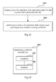
- FIG. 10 is a schematic diagram of a structure of a nonlinear compensating apparatus 1000 of Embodiment 3 of the present disclosure.
- FIG. 11 is a schematic diagram of a structure of a preprocessor 1001 in FIG. 10 ;
- FIG. 12 is a flowchart of a method of preprocessing a transmitted signal by the preprocessor 1001 in FIG. 10 ;
- FIG. 13 is a schematic diagram of a structure of a preprocessing coefficient acquiring unit 1003 in FIG. 10 ;
- FIG. 14 is a schematic diagram of a structure of a comparator 1301 in FIG. 13 ;
- FIG. 15 is a flowchart of a method of acquiring a preprocessing coefficient of Embodiment 3 of the present disclosure
- FIG. 16 is a schematic diagram of a structure of a nonlinear compensating apparatus 1600 of Embodiment 4 of the present disclosure.
- FIG. 17 is a schematic diagram of a structure of a nonlinear compensating coefficient acquiring unit of the present disclosure.
- FIG. 18 is a flowchart of a method for determining a nonlinear compensating coefficient by using a nonlinear compensating coefficient acquiring unit
- FIG. 19 is a schematic diagram of a structure of a transmitter 1900 of Embodiment 5 of the present disclosure.
- FIG. 20 is a schematic diagram of a structure of a communication system 2000 of Embodiment 6 of the present disclosure.
- FIG. 21 is a flowchart of a nonlinear compensating method of Embodiment 7 of the present disclosure.
- FIG. 22 is a flowchart of a nonlinear compensating method of Embodiment 8 of the present disclosure.
- FIG. 1 is a flowchart of performing nonlinear compensation by a nonlinear compensating apparatus in the prior art.
- the nonlinear compensating apparatus includes a nonlinear channel 101 , a gain controller 102 , a predistortion measurer 103 and a predistorter 104 .
- the predistortion measurer 103 and the predistorter 104 are completely the same; and X(t) is a transmitted signal, Z(t) is a predistorted signal, a received signal Y(t) is obtained by transmitting the Z(t) via the nonlinear channel 101 , a signal Y′(t) is obtained by performing gain control on the Y(t) by the gain controller 102 , power of the signal Y′(t) being identical to that of the transmitted signal X(t).
- a nonlinear compensating coefficient needed by the predistorter 104 in performing predistortion is obtained by repeated measurements by the predistortion measurer 103 , and in performing measurement for the first time, the predistorter 104 is removed, hence, X(t) is identical to Z(t).
- the predistortion measurer 103 may calculate an initial parameter of the predistortion measurer 103 , and the predistorter 104 is incorporated into the nonlinear compensating apparatus after calculating the initial parameter.
- the transmitted signal X(t) is again inputted into the nonlinear compensating apparatus, so as to obtain the signal Y′(t), a signal Z′(t) is obtained after the signal Y′(t) passes through the predistortion measurer 103 , and the parameter of the predistortion measurer 103 is adjusted by comparing the signal Z′(t) with the signal Z(t); the adjusted predistortion measurer 103 is copied to a position of the predistorter 104 ; and the above processes are repeated, until a difference e(t) between Z′(t) and the signal Z(t) is in a predefined range.
- FIG. 2( a ) is an input-output curve diagram of the nonlinear channel 101 in FIG. 1
- FIG. 2( b ) is an input-output curve diagram of the predistortion measurer 103 and the predistorter 104 in FIG. 1
- a curve 0-P is an input-output curve of the nonlinear channel 101 .
- a range of the input signal X(t) is 0-VppX
- a range of the output signal Y′(t) is 0-VppY′1, corresponding to a 0-P1 part of the curve; and these may be used to obtain the input-output curve 0-Q1 of the predistortion measurer 103 and the predistorter 104 in FIG. 2( b ) .
- the nonlinear compensating apparatus in the prior art needs to repeatedly measure signals of a receiver end in obtaining a nonlinear compensating coefficient, and calculates repeatedly based on the signals at the data transmitter end and the signals at the data receiver end. Hence, complexity of circuits of the whole communication system and complexity of calculation are greatly increased.
- the embodiments of the present disclosure provide a nonlinear compensating apparatus and method, which may efficiently compensate for nonlinear distortion produced in a communication process, thereby improving communication quality, and lowering complexity of circuits of the communication system and complexity of calculation.
- the nonlinear compensating apparatus and method provided by the embodiments of the present disclosure may use only the part 0-Q1 in the input-output curve, hence efficient nonlinear compensation may be performed without needing to perform measurement at the receiver end for many times, thereby greatly lowering complexity of circuits of the communication system and complexity of calculation.
- FIG. 3 is a schematic diagram of a structure of the nonlinear compensating apparatus 300 of Embodiment 1 of the present disclosure, the apparatus being provided at a UE (user equipment) side.
- the apparatus 300 includes a preprocessor 301 and a predistorter 302 .
- the preprocessor 301 is configured to preprocess a transmitted signal X(t) according to a pre-obtained preprocessing coefficient, so as to obtain a preprocessed signal X′(t); and the predistorter 302 is configured to perform predistortion for the preprocessed signal X′(t), so as to obtain a predistorted signal Z(t); so that a result of comparison of a characteristic parameter of the signal that has been preprocessed and then predistorted with that of the transmitted signal satisfies a predetermined condition.
- a received signal Y(t) obtained at a receiver end is approximately identical to the preprocessed signal X′(t) (which are completely identical in an ideal case), and the original transmitted signal X(t) may be well recovered by performing inverse transform on the preprocessing of the received signal Y(t).
- the signal that has been preprocessed and then predistorted is made to be identical to the transmitted signal by preprocessing and then predistorting the transmitted signal.
- the characteristic parameter of the signal that has been preprocessed and then predistorted is generally not completely identical to that of the transmitted signal.
- characteristic parameters that is, indices, such as one or more of power, amplitude and mean values, of the signal Z(t) that has been preprocessed and then predistorted and the transmitted signal X(t) may be compared; however, the present disclosure is not limited to such indices.
- indices such as one or more of power, amplitude and mean values
- a ratio of the amplitude of the two signals may be compared; when the ratio is equal to 1, the amplitude of the two signals is completely identical, and this is a most ideal case; and when the ratio is in a predefined range (for example, 1 ⁇ e ⁇ 5 ⁇ 1+e ⁇ 5 ), it may be deemed that the compensation requirement is satisfied.
- a difference between the mean values of the two signals may be compared; when the difference is equal to 0, the mean values of the two signals are completely identical, and this is a most ideal case; and when the difference is in a predefined range (for example, ⁇ e ⁇ 5 ⁇ e ⁇ 5 ), it may be deemed that the compensation requirement is satisfied.
- the amplitude and the mean values of the two signals may be compared at the same time, and when the ratio of the amplitude and the difference between the mean values are in the above ranges respectively, it may be deemed that the compensation requirement is satisfied.
- the comparison of the characteristic parameters of the two signals is illustrated above, the present disclosure is not limited to these characteristic parameters and parameter ranges, and the parameter ranges may be determined according to an actual situation.
- FIG. 4 is a schematic diagram of a structure of a nonlinear compensating apparatus 400 of Embodiment 2 of the present disclosure, the apparatus being provided at a transmitter end of a signal.
- the apparatus 400 includes a preprocessor 401 , a predistorter 402 and a preprocessing coefficient acquiring unit 403 .
- the preprocessor 401 is configured to preprocess a transmitted signal X(t) according to a pre-obtained preprocessing coefficient, so as to obtain a preprocessed signal X′(t); and the predistorter 402 is configured to perform predistortion for the preprocessed signal X′(t), so as to obtain a predistorted signal Z(t); so that a result of comparison of a characteristic parameter of the predistorted signal Z(t) with that of the transmitted signal X(t) satisfies a predetermined condition;
- the preprocessing coefficient acquiring unit 403 is configured to determine a preprocessing coefficient used by the preprocessor 401 in preprocessing the transmitted signal.
- the preprocessing coefficient is, for example, a zooming coefficient and/or a translating coefficient; however, the present disclosure is not limited thereto.
- the structure of the preprocessor 401 , the structure of the preprocessing coefficient acquiring unit 403 and the method for acquiring the preprocessing coefficient by using the preprocessor 401 and the preprocessing coefficient acquiring unit 403 shall be described with reference to FIGS. 5-8 , which shall not be described herein any further, and the present disclosure is not limited to such structures and method.
- the preprocessor 401 is configured to preprocess the transmitted signal, so that the result of comparison of the characteristic parameter of the predistorted signal Z(t) with that of the transmitted signal X(t) satisfies the predetermined condition.
- the characteristic parameter is, for example, power, amplitude and a mean value of a signal.
- the structure of the preprocessor 401 is set. For example, when the amplitude of the signal needs to be compared, a zooming unit configured to adjust the amplitude is correspondingly provided in the preprocessor 401 ; and when the mean value of the signal needs to be compared, a translating unit configured to adjust the mean value is correspondingly provided in the preprocessor 401 .
- FIG. 5 is a schematic diagram of the structure of the preprocessor 401 in FIG. 4 , corresponding to a case where amplitude and means values of signals needs to be compared at the same time; however, the present disclosure is not limited to such a structure.
- the preprocessor 401 includes a clipping unit 501 , a zooming unit 502 and a translating unit 503 .
- the clipping unit 501 is configured to clip a part of the amplitude of the transmitted signal X(t) that is greater than a predetermined value; r is a predetermined clipping coefficient; for example, the clipping coefficient may be a numerical value taken from ⁇ square root over (10) ⁇ ⁇ 4; however, the present disclosure is not limited to numerical values in this range. For example, if a mean square root value of the transmitted signal X(t) is k, after being clipped by the clipping unit 501 , the amplitude of the signal X(t) greater than r ⁇ K or less than ⁇ r ⁇ K will be compulsively set to be r ⁇ K or ⁇ r ⁇ K.
- a process of clipping the transmitted signal X(t) shall be described with reference to FIG. 8 , and shall not be described herein any further.
- the zooming unit 502 is configured to perform zooming on the amplitude of the clipped signal according to a pre-obtained zooming coefficient
- the translating unit 503 is configured to perform translation on a mean value of the zoomed signal according to a pre-obtained translating coefficient.
- the linear processing including the zooming processing and the translation processing by using the zooming unit 502 and the translating unit 503 may possibly have effect on a signal to noise ratio of the communication system under a condition of noise, hence for example the clipping unit 501 may be provided, so that the predistorted signal obtains a balance between a clipped noise and lowering of the signal to noise ratio brought about by lowering of power, thereby achieving a better compensation result.
- FIG. 6 is a flowchart of a method for preprocessing the transmitted signal by the preprocessor 401 . As shown in FIG. 6 , the method includes:
- step 601 clipping a part of the amplitude of the transmitted signal X(t) that is greater than a predetermined value
- step 602 performing zooming on the amplitude of the clipped signal according to a pre-obtained zooming coefficient
- step 603 performing translation on a mean value of the zoomed signal according to a pre-obtained translating coefficient.
- the zooming unit 502 and the translating unit 503 is configured to perform zooming and translation on the amplitude and the mean value of the clipped signal according to the pre-obtained zooming coefficient and translating coefficient
- the predistorter 402 is configured to perform predistortion for the zoomed and translated signal, and based on results of comparison of the amplitude and mean values of the signal that is preprocessed and then predistorted and the transmitted signal
- the preprocessing coefficient acquiring unit 403 is configured to adjust the zooming coefficient and translating coefficient, until the results of comparison of the amplitude and mean values of the signal that is preprocessed and then predistorted and the transmitted signal satisfy the predetermined condition, and is configured to determine a zooming coefficient and a translating coefficient used when the predetermined condition is satisfied as the zooming coefficient and translating coefficient, thereby acquiring the preprocessing coefficient.
- the predetermined condition is identical to that in Embodiment 1, and shall not be described herein any further.
- FIG. 7 is a schematic diagram of a structure of the preprocessing coefficient acquiring unit 403 in FIG. 4 ; however, the present disclosure is not limited to such a structure.
- the preprocessing coefficient acquiring unit 403 includes a comparator 701 , a multiplier 702 and an adder 703 .
- the preprocessing coefficient acquiring unit 403 is configured to adjust the zooming coefficient and translating coefficient for N times, so that the results of comparison of the amplitude and mean values of the predistorted signal Z(t)N and the transmitted signal X(t) obtained after N times of adjustment satisfy the predetermined condition; where, N is an integer greater than or equal to 1.
- the comparator 701 is configured to compare the amplitude of a predistorted signal of an i-th time of adjustment in the N times of adjustment with that of the transmitted signal, so as to obtain an amplitude error parameter of the i-th time of adjustment, and compare a mean value of the predistorted signal of the i-th time of adjustment with that of the transmitted signal, so as to obtain a mean value error parameter of the i-th time of adjustment; where, 0 ⁇ i ⁇ N.
- the multiplier 702 is configured to multiply the amplitude error parameter of the current adjustment by a zooming parameter of an (i ⁇ 1)-th time of adjustment, so as to obtain the zooming coefficient of the i-th time of adjustment, and multiply the amplitude error parameter of the i-th time of adjustment by the mean value error parameter of the i-th time of adjustment;
- the adder 703 is configured to add a result obtained by the multiplier 702 through multiplying the amplitude error parameter of the i-th time of adjustment by the mean value error parameter of the i-th time of adjustment to the translating coefficient of the (i ⁇ 1)-th time of adjustment, so as to obtain the translating coefficient of the current adjustment.
- the comparator 701 is configured to compare the amplitude of the predistorted signal of the i-th time of adjustment in the N times of adjustment with that of the transmitted signal, so as to obtain the amplitude error parameter of the i-th time of adjustment, and compare the mean value of the predistorted signal of the i-th time of adjustment in the N times of adjustment with that of the transmitted signal X(t), so as to obtain the mean value error parameter of the i-th time of adjustment; where, 0 ⁇ i ⁇ N.
- FIG. 8 is a schematic diagram of a structure of the comparator 701 in FIG. 7 ; however, the present disclosure is not limited to such a structure. As shown in FIG. 8 , the comparator 701 includes mean value calculation units 801 and 802 , amplitude calculation units 803 and 804 , a subtractor 805 and a divider 806 .
- the transmitted signal X(t) and a predistorted signal Z(t) i are input signals of the comparator 701 , structures of the mean value calculation units 801 and 802 are identical, the mean value calculation units 801 and 802 respectively calculate mean values of the signal X(t) and the signal Z(t)i, structures of the amplitude calculation units 803 and 804 are also identical, and the amplitude calculation units 803 and 804 respectively calculate amplitude of the signal X(t) and the signal Z(t) i ; and the mean values of the signal X(t) and the signal Z(t) i are subtracted by using the subtracter 805 , so as to obtain the mean value error parameter e mean (t) i of the i-th time of adjustment, and the amplitude of the signal X(t) and the signal Z(t) i is divided by using the divider 806 , so as to obtain the amplitude error parameter e Vpp (t) i of the i-th time of adjustment.
- the preprocessing coefficient is acquired by using the preprocessing coefficient acquiring unit 403 .
- FIG. 9 is a flowchart of a method of acquiring the preprocessing coefficient by using the preprocessing coefficient acquiring unit 403 of this embodiment; however, the present disclosure is not limited to such a method.
- 901 denotes the clipping unit 501 in FIGS. 5
- 902 and 903 denote the multiplier 702 in FIG. 7
- 904 denotes the adder 703 in FIG.
- 905 and 906 denote respectively a first memory and a second memory; for example, the first memory 905 and the second memory 906 may be provided respectively, and may also be provided integrally; and they may be provided in the preprocessing coefficient acquiring unit 403 , and may also be provided in the nonlinear compensating apparatus 400 , independent of the preprocessing coefficient acquiring unit 403 ; 907 denotes the zooming unit 502 in FIG. 5 , which may be, for example, a multiplier, in this embodiment; and 908 denotes the translating unit 503 in FIG. 5 , which may be, for example, an adder, in this embodiment.
- the first memory 905 is configured to store the zooming parameter, an initial value of the zooming parameter being, for example, 1; and the second memory 906 is configured to store the translating parameter, an initial value of the translating parameter being, for example, 0.
- the zooming unit 502 and the translating unit 503 is configured to perform the i-th time of adjustment in the N times of adjustment, the amplitude error parameter e Vpp (t) i of the i-th time of adjustment obtained in FIG.
- the zooming parameter P Vpp (i ⁇ 1) of the (i ⁇ 1)-th time of adjustment by using the multiplier 902 is multiplied by the zooming parameter P Vpp (i ⁇ 1) of the (i ⁇ 1)-th time of adjustment by using the multiplier 902 , so as to obtain a zooming coefficient P Vpp (i) of the i-th time of adjustment, and store it in the first memory 905 ;
- the signal obtained by clipping the transmitted signal X(t) by the clipping unit 901 is multiplied by the zooming coefficient P Vpp (i) of the i-th time of adjustment by using the multiplier 907 , that is, adjustment of the amplitude is performed, so as to obtain a zoomed signal of the i-th time of adjustment;
- the amplitude error parameter e Vpp (t) i of the i-th time of adjustment obtained in FIG.
- the amplitude adjusted signal of the i-th time is added to the translating coefficient P mean (i) of the i-th time of adjustment by using the adder 908 , so as to obtain the mean value translated signal X′(t) i of the i-th time; the signal X′(t) i is distorted by the predistorter 402 , so as to obtain a distorted signal Z′(t) i ; and the above process is repeated, until the results of comparison of the amplitude and mean values of the signal Z′(t) N obtained after N times of adjustment and the
- FIG. 10 is a schematic diagram of a structure of a nonlinear compensating apparatus 1000 of Embodiment 3 of the present disclosure, the apparatus being provided at a transmitter end of a signal.
- the apparatus 1000 includes a preprocessor 1001 , a predistorter 1002 and a preprocessing coefficient acquiring unit 1003 .
- the preprocessor 1001 is configured to preprocess a transmitted signal X(t) according to a pre-obtained preprocessing coefficient, so as to obtain a preprocessed signal X′(t); and the predistorter 1002 is configured to perform predistortion for the preprocessed signal X′(t), so as to obtain a predistorted signal Z(t); so that a result of comparison of a characteristic parameter of the predistorted signal Z(t) with that of the transmitted signal X(t) satisfies a predetermined condition;
- the preprocessing coefficient acquiring unit 1003 is configured to determine a preprocessing coefficient used by the preprocessor 1001 in preprocessing the transmitted signal.
- the preprocessor 1001 includes a clipping unit and a zooming unit, and the preprocessing coefficient is a zooming coefficient only; however, the present disclosure is not limited to such a case.
- the predetermined condition is identical to that in Embodiment 1, and shall not be described herein any further.
- FIG. 11 is a schematic diagram of a structure of the preprocessor 1001 in FIG. 10 , corresponding to a case where amplitude of signals is compared; however, the present disclosure is not limited to such a structure.
- the preprocessor 1001 includes a clipping unit 1101 and a zooming unit 1102 .
- the clipping unit 1101 is identical to that described in Embodiment 2, and shall not be described herein any further.
- the zooming unit 1102 is configured to perform zooming on the amplitude of the clipped signal according to a pre-obtained zooming coefficient.
- the linear processing including the zooming processing by using the zooming unit 1102 may possibly have effect on a signal to noise ratio of the communication system under a condition of noise, hence for example the clipping unit 1101 may be provided, so that the nonlinear compensated signal obtains a balance between a clipped noise and lowering of the signal to noise ratio brought about by lowering of power, thereby achieving a better compensation result.
- FIG. 12 is a flowchart of a method for preprocessing the transmitted signal by the preprocessor 1001 . As shown in FIG. 12 , the method includes:
- step 1201 clipping a part of the amplitude of the transmitted signal X(t) that is greater than a predetermined value
- step 1202 performing zooming on the amplitude of the clipped signal according to a pre-obtained zooming coefficient.
- FIG. 13 is a schematic diagram of a structure of a preprocessing coefficient acquiring unit 1003 in FIG. 10 ; however, the present disclosure is not limited to such a structure.
- the preprocessing coefficient acquiring unit 1003 includes a comparator 1301 and a multiplier 1302 .
- the comparator 1301 is configured to compare amplitude of a nonlinear compensated signal of an i-th time of adjustment in N times of adjustment with that of the transmitted signal, so as to obtain an amplitude error parameter of the i-th time of adjustment; where, 0 ⁇ i ⁇ N;
- the multiplier 1302 is configured to multiply the amplitude error parameter of the i-th time of adjustment by a zooming parameter of an (i ⁇ 1)-th time of adjustment, so as to obtain the zooming coefficient of the current time.
- the zooming unit 1102 is configured to perform zooming on the amplitude of the clipped signal according to the pre-obtained zooming coefficient
- the predistorter 1002 is configured to perform predistortion for the zoomed signal, and based on a result of comparison of the amplitude of the signal that is preprocessed and then predistorted and the transmitted signal
- the preprocessing coefficient acquiring unit 1003 is configured to adjust the zooming coefficient, until the result of comparison of the amplitude of the signal that is preprocessed and then predistorted and the transmitted signal satisfy the predetermined condition, and is configured to determine a zooming coefficient used when the predetermined condition is satisfied as the zooming coefficient, thereby acquiring the preprocessing coefficient.
- the predetermined condition is identical to that described in Embodiment 1, and shall not be described herein any further.
- the comparator 1301 is configured to compare the amplitude of the predistorted signal of the i-th time of adjustment in the N times of adjustment with that of the transmitted signal, so as to obtain the amplitude error parameter of the i-th time of adjustment; where, 0 ⁇ i ⁇ N.
- FIG. 14 is a schematic diagram of a structure of the comparator 1301 in FIG. 13 ; however, the present disclosure is not limited to such a structure.
- the comparator 1301 includes amplitude calculation units 1401 and 1402 , and a divider 1403 .
- the transmitted signal X(t) and a nonlinear compensated signal Z(t) i are input signals of the comparator 1301 , structures of the amplitude calculation units 1401 and 1402 are identical, and the amplitude calculation units 1401 and 1402 respectively calculate amplitude of the signal X(t) and the signal Z(t) i ; and the amplitude of the signal X(t) and the signal Z(t) i is divided by using the divider 1403 , so as to obtain the amplitude error parameter e Vpp (t) i of the i-th time of adjustment.
- the preprocessing coefficient is acquired by using the preprocessing coefficient acquiring unit 1003 .
- FIG. 15 is a flowchart of a method of acquiring the preprocessing coefficient by using the preprocessing coefficient acquiring unit 1003 of this embodiment; however, the present disclosure is not limited to such a method.
- 1501 denotes the clipping unit 1101 in FIG. 11
- 1502 denotes the multiplier 1302 in FIGS. 13
- 1503 denotes a third memory; for example, the third memory may be provided in the preprocessing coefficient acquiring unit 1003 , and may also be provided in the nonlinear compensating apparatus 1000 , independent of the preprocessing coefficient acquiring unit 1003
- 1504 denotes the zooming unit 1102 in FIG. 11 , which may be, for example, a multiplier, in this embodiment.
- the third memory 1503 is configured to store the zooming parameter, an initial value of the zooming parameter being, for example, 1.
- the zooming unit 1102 is configured to perform the i-th time of adjustment in the N times of adjustment, the amplitude error parameter e Vpp (t) i of the i-th time of adjustment obtained in FIG.
- the signal obtained by clipping the transmitted signal X(t) by the clipping unit 1501 is multiplied by the zooming coefficient P Vpp (i) of the i-th time of adjustment by using the multiplier 1304 , that is, adjustment of the amplitude is performed, so as to obtain a zoomed signal X′(t) i of the i-th time of adjustment; the signal X′(t) i is distorted by the predistorter 1002 , so as to obtain a distorted signal Z′(t) i ; and the above process is repeated, until the result of comparison of the amplitude of the signal Z′(t) N obtained after N times of adjustment and the transmitted signal X(t) satisfy the predetermined condition
- the preprocessor when only the mean value of the nonlinear compensated signal Z(t) is compared with that of the transmitted signal X(t), the preprocessor includes the clipping unit and the translating unit, and the preprocessing coefficient includes only the translating coefficient. At this moment, calculation of the translating coefficient in FIG. 9 in Embodiment 2 may only be used, and the part of calculating of the zooming coefficient and the zooming unit may be removed.
- FIG. 16 is a schematic diagram of a structure of a nonlinear compensating apparatus 1600 of Embodiment 4 of the present disclosure, the apparatus being provided at a transmitter end of a signal.
- the apparatus 1600 includes a preprocessor 1601 , a linear damage device 1602 , a predistorter 1603 and a linear compensator 1604 .
- the preprocessor 1601 is configured to preprocess a transmitted signal X(t) according to a pre-obtained preprocessing coefficient, so as to obtain a preprocessed signal;
- the linear damage device 1602 is configured to perform linear damage processing on the preprocessed signal;
- the predistorter 1603 is configured to perform predistortion for the linearly damaged signal;
- the linear compensator 1604 is configured to linearly compensate for the predistorted signal, so as to obtain a linearly compensated signal; so that a result of comparison of a characteristic parameter of the predistorted signal Z(t) with that of the transmitted signal X(t) satisfies a predetermined condition.
- the linear damage device 1602 and the linear compensator 1604 are reverse to each other, that is, processing of a signal in the linear compensator 1604 is a reverse process of processing of the signal in the linear damage device 1602 .
- Embodiment 1 Different from Embodiment 1, a long memory effect resulted from the linear damage in the communication system is removed in this embodiment by providing the mutually reverse linear damage device and linear compensator, so that the nonlinear compensating apparatus only compensates for the nonlinear damage in which relatively short memory is remained, thereby overcoming a problem of power loss resulted from the linear compensation at the transmitter end.
- a received signal Y(t) obtained at a receiver end is approximately identical to the preprocessed signal X′(t) (which are completely identical in an ideal case), and the original transmitted signal X(t) may be well recovered by performing inverse transform on the preprocessing of the received signal Y(t).
- the signal that has been preprocessed and then predistorted is made to be identical to the transmitted signal by preprocessing and then predistorting the transmitted signal.
- the characteristic parameter of the signal that has been preprocessed and then predistorted is generally not completely identical to that of the transmitted signal.
- the predetermined condition in this embodiment is identical to that in Embodiment 1, and the process of predistortion in this embodiment is identical to that in Embodiment 2 or 3, which shall not be described herein any further.
- the predistortion performed by the predistorter may include the nonlinear compensation performed according to the preobtained nonlinear compensation coefficient, and the nonlinear compensation coefficient may be obtained by using any method in the prior art.
- a nonlinear compensating coefficient acquiring unit configured to determine the preobtained nonlinear compensating coefficient may be provided in the nonlinear compensating apparatus 300 ( 400 , 900 , 1600 ), so as to provide the nonlinear compensation coefficient to the predistorter for performing nonlinear compensation.
- FIG. 17 is a schematic diagram of a structure of the nonlinear compensating coefficient acquiring unit. As shown in FIG. 17 , the nonlinear compensating coefficient acquiring unit includes a nonlinear transmitting unit 1701 , a linear filtering unit 1702 and a calculating unit 1703 ;
- the nonlinear transmitting unit 1701 and the linear filtering unit 1702 are connected to each other, and an input signal and an output signal of the nonlinear transmitting unit 1701 need to be measured once; and the calculating unit 1703 is configured to obtain the nonlinear compensating coefficient based on the input signal and the output signal of the nonlinear transmitting unit 1701 .
- the nonlinear transmitting unit 1701 and the linear filtering unit 1702 are simulation models set up for nonlinear distortion and linear distortion in the communication system.
- a memory effect is extremely serious in some communication systems (such as optical fiber communication)
- the linear filtering unit 1702 and the nonlinear transmitting unit 1701 are provided.
- a method for determining a nonlinear compensating coefficient by using the nonlinear compensating coefficient acquiring unit is illustrated below; however, the present disclosure is not limited to such a method.
- FIG. 18 is a flowchart of the method for determining the nonlinear compensating coefficient by using the nonlinear compensating coefficient acquiring unit.
- the nonlinear transmitting unit 1701 is provided after the linear filtering unit 1702 , and the calculating unit 1703 is configured to calculate the nonlinear compensating coefficient according to the input signal S 1 of the nonlinear transmitting unit 1701 and the output signal S 2 of the nonlinear transmitting unit 1701 .
- the relevant art may be used for calculating the nonlinear compensating coefficient.
- a recursive least square (RLS) method or a least mean square (LMS) method may be used to obtain a tap coefficient of the linear filtering unit 1702 , and the output signal of the nonlinear transmitting unit 1701 may be obtained according to the input signal of the nonlinear transmitting unit 1701 , the output signal of the linear filtering unit 1702 and the tap coefficient.
- RLS recursive least square
- LMS least mean square
- a Volterra expansion method may be employed to determine a nonlinear compensation item, and an initial parameter of the predistorter may be obtained according to the least square method or the least mean square method.
- the calculating unit still calculates the nonlinear compensating coefficient according to the input signal of the nonlinear transmitting unit 1701 and the output signal of the nonlinear transmitting unit 1701 . And the method of calculation is similar to that described above, and shall not be described herein any further.
- the nonlinear compensating coefficient may be obtained by performing measurement at the transmitter end once, thereby lowering complexity of circuits of the communication system and complexity of calculation.
- FIG. 19 is a schematic diagram of a structure of a transmitter 1900 of Embodiment 5 of the present disclosure.
- the transmitter 1900 includes the nonlinear compensating apparatus 1901 ( 300 , 400 , 900 , 1600 ) in any one of embodiments 1-4.
- FIG. 20 is a schematic diagram of a structure of a communication system 2000 of Embodiment 6 of the present disclosure.
- the communication system 2000 includes the transmitter 2001 ( 1900 ) of Embodiment 5 and a receiver 2002 .
- the receiver 2002 further includes a post-compensator 2003 configured to perform post nonlinear compensation on a received signal Y(t) according to a result of comparison of the received signal and a signal X′(t) preprocessed at a transmitter end.
- a nonlinear compensating coefficient used by the post-compensator 2003 may be obtained by the nonlinear compensating coefficient acquiring unit shown in FIG. 17 .
- it may also be obtained by using the method shown in FIG. 18 , which shall not be described herein any further.
- FIG. 21 is a flowchart of a nonlinear compensating method of Embodiment 7 of the present disclosure, corresponding to the nonlinear compensating apparatus of Embodiment 1. As shown in FIG. 21 , the method includes:
- step 2101 preprocessing a transmitted signal according to a pre-obtained preprocessing coefficient
- step 2102 performing predistortion for the preprocessed signal
- a received signal obtained at a receiver end is approximately identical to the preprocessed signal (which are completely identical in an ideal case), and the original transmitted signal may be well recovered by performing inverse transform on the preprocessing of the received signal.
- the signal that has been preprocessed and then predistorted is made to be identical to the transmitted signal by preprocessing and then predistorting the transmitted signal.
- the characteristic parameter of the signal that has been preprocessed and then predistorted is generally not completely identical to that of the transmitted signal.
- the predetermined condition in this embodiment is identical to that in Embodiment 1, and the method for obtaining the preprocessing coefficient used in preprocessing in this embodiment is identical to that in Embodiment 2 or 3, which shall not be described herein any further.
- the predistortion may include the nonlinear compensation performed according to the preobtained nonlinear compensation coefficient.
- the method for obtaining the nonlinear compensation coefficient in this embodiment is identical to that in embodiments 1-4, which shall not be described herein any further.
- FIG. 22 is a flowchart of a nonlinear compensating method of Embodiment 8 of the present disclosure, corresponding to the nonlinear compensating apparatus of Embodiment 4. As shown in FIG. 22 , the method includes:
- step 2201 preprocessing a transmitted signal according to a pre-obtained preprocessing coefficient
- step 2202 performing linear damage processing on the preprocessed signal
- step 2203 performing predistortion for the linearly damaged signal
- step 2204 linearly compensating for the predistorted signal
- a received signal obtained at a receiver end is approximately identical to the preprocessed signal (which are completely identical in an ideal case), and the original transmitted signal may be well recovered by performing inverse transform on the preprocessing of the received signal.
- the signal that has been preprocessed and then predistorted is made to be identical to the transmitted signal by preprocessing and then predistorting the transmitted signal.
- the characteristic parameter of the signal that has been preprocessed and then predistorted is generally not completely identical to that of the transmitted signal.
- the predetermined condition in this embodiment is identical to that in Embodiment 1, the method for obtaining the preprocessing coefficient used in preprocessing in this embodiment is identical to that in Embodiment 2 or 3, and the descriptions of linear damage processing and linear compensation in this embodiment are identical to that in Embodiment 4, which shall not be described herein any further.
- the predistortion may include the nonlinear compensation performed according to the preobtained nonlinear compensation coefficient.
- the method for obtaining the nonlinear compensation coefficient in this embodiment is identical to that in embodiments 1-4, which shall not be described herein any further.
- the above apparatuses and methods of the present disclosure may be implemented by hardware, or by hardware in combination with software.
- the present disclosure relates to such a computer-readable program that when the program is executed by a logic device, the logic device is enabled to carry out the apparatus or components as described above, or to carry out the methods or steps as described above.
- the present disclosure also relates to a storage medium for storing the above program, such as a hard disk, a floppy disk, a CD, a DVD, and a flash memory, etc.
Abstract
A nonlinear compensating apparatus and method, a transmitter and a communication system are provided. The apparatus includes a preprocessor configured to preprocess a transmitted signal according to a pre-obtained preprocessing coefficient and a predistorter configured to perform predistortion for the preprocessed signal, and a result of comparison of a characteristic parameter of the signal that has been preprocessed and then predistorted with that of the transmitted signal satisfies a predetermined condition. By preprocessing the transmitted signal at the transmitter end, the embodiments of the present disclosure may perform efficient nonlinear compensation only needing to measure at the transmitter end and without needing to perform many times of measurement at the receiver end, and may lower complexity of circuits of the communication system and complexity of calculation.
Description
This application is a continuation of International Application No. PCT/CN2014/075027, filed Apr. 10, 2014, and claims the benefit of Chinese Application No. 201310128976.2, filed Apr. 15, 2013, the disclosures of all of which are incorporated herein by reference.
The present disclosure relates to the field of communications, and in particular to a nonlinear compensating apparatus and method in a communication system, a transmitter and a communication system.
Currently, in a communication system, transmission of a transmitted signal at a data transmitter end via the communication system produces nonlinear distortion resulted from a nonlinear effect in the communication system, thereby resulting in degradation of communication quality.
In the prior art, nonlinear distortion produced in signal transmission is generally compensated for by performing predistortion at a data transmitter end, so as to improve communication quality. And a nonlinear compensating coefficient used in the predistortion may be obtained in a direct learning method or an indirect learning method. However, either the direct learning method or the indirect learning method needs to measure signals at the data receiver end many times after the signals pass through the communication system, and perform many times of iteration calculation based on the signals at the data transmitter end and the signals at the data receiver end. Hence, complexity of circuits of the whole communication system and complexity of calculation are greatly increased.
It should be noted that the above description of the background is merely provided for clear and complete explanation of the present disclosure and for easy understanding by those skilled in the art. And it should not be understood that the above technical solution is known to those skilled in the art as it is described in the background of the present disclosure.
An object of the embodiments of the present disclosure is to provide a nonlinear compensating apparatus and method, which may efficiently compensate for nonlinear distortion produced in a communication process, thereby improving communication quality, and lowering complexity of circuits of the communication system and complexity of calculation.
According to an aspect of the embodiments of the present disclosure, there is provided a nonlinear compensating apparatus, including: a preprocessor configured to preprocess a transmitted signal according to a pre-obtained preprocessing coefficient; and a predistorter configured to perform predistortion for the preprocessed signal; wherein a result of comparison of a characteristic parameter of the signal that has been preprocessed and then predistorted with that of the transmitted signal satisfies a predetermined condition.
According to another aspect of the embodiments of the present disclosure, there is provided a nonlinear compensating method, including: preprocessing a transmitted signal according to a pre-obtained preprocessing coefficient; performing predistortion for the preprocessed signal; wherein a result of comparison of a characteristic parameter of the signal that has been preprocessed and then predistorted with that of the transmitted signal satisfies a predetermined condition.
An advantage of the embodiments of the present disclosure exists in that nonlinear distortion produced in a communication process is efficiently compensated, and complexity of circuits of the communication system and complexity of calculation are lowered.
With reference to the following description and drawings, the particular embodiments of the present disclosure are disclosed in detail, and the principles of the present disclosure and the manners of use are indicated. It should be understood that the scope of the embodiments of the present disclosure is not limited thereto. The embodiments of the present disclosure contain many alternations, modifications and equivalents within the scope of the terms of the appended claims.
Features that are described and/or illustrated with respect to one embodiment may be used in the same way or in a similar way in one or more other embodiments and/or in combination with or instead of the features of the other embodiments.
It should be emphasized that the term “comprise/include” when used in this specification is taken to specify the presence of stated features, integers, steps or components but does not preclude the presence or addition of one or more other features, integers, steps, components or groups thereof.
Many aspects of the disclosure can be better understood with reference to the following drawings. The components in the drawings are not necessarily to scale, emphasis instead being placed upon clearly illustrating the principles of the present disclosure. To facilitate illustrating and describing some parts of the disclosure, corresponding portions of the drawings may be exaggerated or reduced in size. Elements and features depicted in one drawing or embodiment of the disclosure may be combined with elements and features depicted in one or more additional drawings or embodiments. Moreover, in the drawings, like reference numerals designate corresponding parts throughout the several views and may be used to designate like or similar parts in more than one embodiment. In the drawings:
These and further aspects and features of the present disclosure will be apparent with reference to the following description and attached drawings. In the description and drawings, particular embodiments of the disclosure have been disclosed in detail as being indicative of some of the ways in which the principles of the disclosure may be employed, but it is understood that the disclosure is not limited correspondingly in scope. Rather, the disclosure includes all changes, modifications and equivalents coming within the terms of the appended claims.
Currently, a nonlinear compensating apparatus and method in the prior art need to perform many times of iteration calculation based on the signals at the data transmitter end and the signals at the data receiver end. FIG. 1 is a flowchart of performing nonlinear compensation by a nonlinear compensating apparatus in the prior art. As shown in FIG. 1 , the nonlinear compensating apparatus includes a nonlinear channel 101, a gain controller 102, a predistortion measurer 103 and a predistorter 104. For example, the predistortion measurer 103 and the predistorter 104 are completely the same; and X(t) is a transmitted signal, Z(t) is a predistorted signal, a received signal Y(t) is obtained by transmitting the Z(t) via the nonlinear channel 101, a signal Y′(t) is obtained by performing gain control on the Y(t) by the gain controller 102, power of the signal Y′(t) being identical to that of the transmitted signal X(t).
A nonlinear compensating coefficient needed by the predistorter 104 in performing predistortion is obtained by repeated measurements by the predistortion measurer 103, and in performing measurement for the first time, the predistorter 104 is removed, hence, X(t) is identical to Z(t). According to the signal Z(t) and the signal Y′(t), the predistortion measurer 103 may calculate an initial parameter of the predistortion measurer 103, and the predistorter 104 is incorporated into the nonlinear compensating apparatus after calculating the initial parameter. The transmitted signal X(t) is again inputted into the nonlinear compensating apparatus, so as to obtain the signal Y′(t), a signal Z′(t) is obtained after the signal Y′(t) passes through the predistortion measurer 103, and the parameter of the predistortion measurer 103 is adjusted by comparing the signal Z′(t) with the signal Z(t); the adjusted predistortion measurer 103 is copied to a position of the predistorter 104; and the above processes are repeated, until a difference e(t) between Z′(t) and the signal Z(t) is in a predefined range.
In a normal case, VppY′1<VppX, hence when input of the predistorter 104 is 0-VppX, a corresponding input-output curve is a 0-Q2 part in FIG. 2(b) . A Q1-Q2 part in the input-output curve has not been measured, hence, measurement needs to be performed again, until the whole input-output curve 0-Q in FIG. 2(b) to which the curve 0-P in FIG. 2(a) corresponds is measured.
It can be seen that the nonlinear compensating apparatus in the prior art needs to repeatedly measure signals of a receiver end in obtaining a nonlinear compensating coefficient, and calculates repeatedly based on the signals at the data transmitter end and the signals at the data receiver end. Hence, complexity of circuits of the whole communication system and complexity of calculation are greatly increased.
The embodiments of the present disclosure provide a nonlinear compensating apparatus and method, which may efficiently compensate for nonlinear distortion produced in a communication process, thereby improving communication quality, and lowering complexity of circuits of the communication system and complexity of calculation.
Corresponding to FIG. 2(b) , the nonlinear compensating apparatus and method provided by the embodiments of the present disclosure may use only the part 0-Q1 in the input-output curve, hence efficient nonlinear compensation may be performed without needing to perform measurement at the receiver end for many times, thereby greatly lowering complexity of circuits of the communication system and complexity of calculation.
The nonlinear compensating apparatus and method of the present disclosure shall be described in detail below with reference to the accompanying drawings.
The preprocessor 301 is configured to preprocess a transmitted signal X(t) according to a pre-obtained preprocessing coefficient, so as to obtain a preprocessed signal X′(t); and the predistorter 302 is configured to perform predistortion for the preprocessed signal X′(t), so as to obtain a predistorted signal Z(t); so that a result of comparison of a characteristic parameter of the signal that has been preprocessed and then predistorted with that of the transmitted signal satisfies a predetermined condition.
In this embodiment, a received signal Y(t) obtained at a receiver end is approximately identical to the preprocessed signal X′(t) (which are completely identical in an ideal case), and the original transmitted signal X(t) may be well recovered by performing inverse transform on the preprocessing of the received signal Y(t).
In this embodiment, the signal that has been preprocessed and then predistorted is made to be identical to the transmitted signal by preprocessing and then predistorting the transmitted signal. In practical use, taking such factors as equipment precision, and calculation precision, etc. into account, the characteristic parameter of the signal that has been preprocessed and then predistorted is generally not completely identical to that of the transmitted signal. Thus, by comparing the characteristic parameter of the signal that has been preprocessed and then predistorted with that of the transmitted signal, it may be deemed that a compensation requirement is satisfied when the result of comparison satisfies the predetermined condition.
For example, characteristic parameters, that is, indices, such as one or more of power, amplitude and mean values, of the signal Z(t) that has been preprocessed and then predistorted and the transmitted signal X(t) may be compared; however, the present disclosure is not limited to such indices. For example, a ratio of the amplitude of the two signals may be compared; when the ratio is equal to 1, the amplitude of the two signals is completely identical, and this is a most ideal case; and when the ratio is in a predefined range (for example, 1−e−5˜1+e−5), it may be deemed that the compensation requirement is satisfied. For another example, a difference between the mean values of the two signals may be compared; when the difference is equal to 0, the mean values of the two signals are completely identical, and this is a most ideal case; and when the difference is in a predefined range (for example, −e−5˜e−5), it may be deemed that the compensation requirement is satisfied. For a further example, the amplitude and the mean values of the two signals may be compared at the same time, and when the ratio of the amplitude and the difference between the mean values are in the above ranges respectively, it may be deemed that the compensation requirement is satisfied. The comparison of the characteristic parameters of the two signals is illustrated above, the present disclosure is not limited to these characteristic parameters and parameter ranges, and the parameter ranges may be determined according to an actual situation.
It can be seen from the above embodiment that by preprocessing the transmitted signal at the transmitter end, measurement is only needed to be performed at the transmitter end and many times of measurement at the receiver end are not needed to be performed, thereby efficiently compensating for nonlinear distortion produced in a communication process, improving communication quality, and lowering complexity of circuits of the communication system and complexity of calculation.
The preprocessor 401 is configured to preprocess a transmitted signal X(t) according to a pre-obtained preprocessing coefficient, so as to obtain a preprocessed signal X′(t); and the predistorter 402 is configured to perform predistortion for the preprocessed signal X′(t), so as to obtain a predistorted signal Z(t); so that a result of comparison of a characteristic parameter of the predistorted signal Z(t) with that of the transmitted signal X(t) satisfies a predetermined condition;
and the preprocessing coefficient acquiring unit 403 is configured to determine a preprocessing coefficient used by the preprocessor 401 in preprocessing the transmitted signal.
In this embodiment, the preprocessing coefficient is, for example, a zooming coefficient and/or a translating coefficient; however, the present disclosure is not limited thereto.
In this embodiment, the structure of the preprocessor 401, the structure of the preprocessing coefficient acquiring unit 403 and the method for acquiring the preprocessing coefficient by using the preprocessor 401 and the preprocessing coefficient acquiring unit 403 shall be described with reference to FIGS. 5-8 , which shall not be described herein any further, and the present disclosure is not limited to such structures and method.
In this embodiment, the preprocessor 401 is configured to preprocess the transmitted signal, so that the result of comparison of the characteristic parameter of the predistorted signal Z(t) with that of the transmitted signal X(t) satisfies the predetermined condition. The characteristic parameter is, for example, power, amplitude and a mean value of a signal. Corresponding to a characteristic parameter needing to be compared, the structure of the preprocessor 401 is set. For example, when the amplitude of the signal needs to be compared, a zooming unit configured to adjust the amplitude is correspondingly provided in the preprocessor 401; and when the mean value of the signal needs to be compared, a translating unit configured to adjust the mean value is correspondingly provided in the preprocessor 401. FIG. 5 is a schematic diagram of the structure of the preprocessor 401 in FIG. 4 , corresponding to a case where amplitude and means values of signals needs to be compared at the same time; however, the present disclosure is not limited to such a structure.
As shown in FIG. 5 , the preprocessor 401 includes a clipping unit 501, a zooming unit 502 and a translating unit 503.
The clipping unit 501 is configured to clip a part of the amplitude of the transmitted signal X(t) that is greater than a predetermined value; r is a predetermined clipping coefficient; for example, the clipping coefficient may be a numerical value taken from √{square root over (10)}˜4; however, the present disclosure is not limited to numerical values in this range. For example, if a mean square root value of the transmitted signal X(t) is k, after being clipped by the clipping unit 501, the amplitude of the signal X(t) greater than r×K or less than −r×K will be compulsively set to be r×K or −r×K. A process of clipping the transmitted signal X(t) shall be described with reference to FIG. 8 , and shall not be described herein any further.
The zooming unit 502 is configured to perform zooming on the amplitude of the clipped signal according to a pre-obtained zooming coefficient, and the translating unit 503 is configured to perform translation on a mean value of the zoomed signal according to a pre-obtained translating coefficient.
In this embodiment, the linear processing including the zooming processing and the translation processing by using the zooming unit 502 and the translating unit 503 may possibly have effect on a signal to noise ratio of the communication system under a condition of noise, hence for example the clipping unit 501 may be provided, so that the predistorted signal obtains a balance between a clipped noise and lowering of the signal to noise ratio brought about by lowering of power, thereby achieving a better compensation result.
step 601: clipping a part of the amplitude of the transmitted signal X(t) that is greater than a predetermined value;
step 602: performing zooming on the amplitude of the clipped signal according to a pre-obtained zooming coefficient; and
step 603: performing translation on a mean value of the zoomed signal according to a pre-obtained translating coefficient.
In this embodiment, the zooming unit 502 and the translating unit 503 is configured to perform zooming and translation on the amplitude and the mean value of the clipped signal according to the pre-obtained zooming coefficient and translating coefficient, the predistorter 402 is configured to perform predistortion for the zoomed and translated signal, and based on results of comparison of the amplitude and mean values of the signal that is preprocessed and then predistorted and the transmitted signal, the preprocessing coefficient acquiring unit 403 is configured to adjust the zooming coefficient and translating coefficient, until the results of comparison of the amplitude and mean values of the signal that is preprocessed and then predistorted and the transmitted signal satisfy the predetermined condition, and is configured to determine a zooming coefficient and a translating coefficient used when the predetermined condition is satisfied as the zooming coefficient and translating coefficient, thereby acquiring the preprocessing coefficient.
In this embodiment, the predetermined condition is identical to that in Embodiment 1, and shall not be described herein any further.
The preprocessing coefficient acquiring unit 403 is configured to adjust the zooming coefficient and translating coefficient for N times, so that the results of comparison of the amplitude and mean values of the predistorted signal Z(t)N and the transmitted signal X(t) obtained after N times of adjustment satisfy the predetermined condition; where, N is an integer greater than or equal to 1.
The comparator 701 is configured to compare the amplitude of a predistorted signal of an i-th time of adjustment in the N times of adjustment with that of the transmitted signal, so as to obtain an amplitude error parameter of the i-th time of adjustment, and compare a mean value of the predistorted signal of the i-th time of adjustment with that of the transmitted signal, so as to obtain a mean value error parameter of the i-th time of adjustment; where, 0<i≦N.
the multiplier 702 is configured to multiply the amplitude error parameter of the current adjustment by a zooming parameter of an (i−1)-th time of adjustment, so as to obtain the zooming coefficient of the i-th time of adjustment, and multiply the amplitude error parameter of the i-th time of adjustment by the mean value error parameter of the i-th time of adjustment;
and the adder 703 is configured to add a result obtained by the multiplier 702 through multiplying the amplitude error parameter of the i-th time of adjustment by the mean value error parameter of the i-th time of adjustment to the translating coefficient of the (i−1)-th time of adjustment, so as to obtain the translating coefficient of the current adjustment.
In this embodiment, the comparator 701 is configured to compare the amplitude of the predistorted signal of the i-th time of adjustment in the N times of adjustment with that of the transmitted signal, so as to obtain the amplitude error parameter of the i-th time of adjustment, and compare the mean value of the predistorted signal of the i-th time of adjustment in the N times of adjustment with that of the transmitted signal X(t), so as to obtain the mean value error parameter of the i-th time of adjustment; where, 0<i≦N. FIG. 8 is a schematic diagram of a structure of the comparator 701 in FIG. 7 ; however, the present disclosure is not limited to such a structure. As shown in FIG. 8 , the comparator 701 includes mean value calculation units 801 and 802, amplitude calculation units 803 and 804, a subtractor 805 and a divider 806.
The transmitted signal X(t) and a predistorted signal Z(t)i are input signals of the comparator 701, structures of the mean value calculation units 801 and 802 are identical, the mean value calculation units 801 and 802 respectively calculate mean values of the signal X(t) and the signal Z(t)i, structures of the amplitude calculation units 803 and 804 are also identical, and the amplitude calculation units 803 and 804 respectively calculate amplitude of the signal X(t) and the signal Z(t)i; and the mean values of the signal X(t) and the signal Z(t)i are subtracted by using the subtracter 805, so as to obtain the mean value error parameter emean(t)i of the i-th time of adjustment, and the amplitude of the signal X(t) and the signal Z(t)i is divided by using the divider 806, so as to obtain the amplitude error parameter eVpp(t)i of the i-th time of adjustment.
After the mean value error parameter emean(t)i of (t) the i-th time of adjustment and the amplitude error parameter eVpp(t)i of the i-th time of adjustment are obtained, the preprocessing coefficient is acquired by using the preprocessing coefficient acquiring unit 403.
The first memory 905 is configured to store the zooming parameter, an initial value of the zooming parameter being, for example, 1; and the second memory 906 is configured to store the translating parameter, an initial value of the translating parameter being, for example, 0. When the zooming unit 502 and the translating unit 503 is configured to perform the i-th time of adjustment in the N times of adjustment, the amplitude error parameter eVpp(t)i of the i-th time of adjustment obtained in FIG. 8 is multiplied by the zooming parameter PVpp(i−1) of the (i−1)-th time of adjustment by using the multiplier 902, so as to obtain a zooming coefficient PVpp(i) of the i-th time of adjustment, and store it in the first memory 905; the signal obtained by clipping the transmitted signal X(t) by the clipping unit 901 is multiplied by the zooming coefficient PVpp(i) of the i-th time of adjustment by using the multiplier 907, that is, adjustment of the amplitude is performed, so as to obtain a zoomed signal of the i-th time of adjustment; the amplitude error parameter eVpp(t)i of the i-th time of adjustment obtained in FIG. 8 is multiplied by the mean value error parameter emean(t)i of the i-th time of adjustment by using the multiplier 903, and a result of multiplication is added to the translating coefficient Pmean(i−1) of an (i−1)-th time of adjustment by using the adder 904, so as to obtain the translating coefficient Pmean(i) of the i-th time of adjustment, and store it in the second memory 906; the amplitude adjusted signal of the i-th time is added to the translating coefficient Pmean(i) of the i-th time of adjustment by using the adder 908, so as to obtain the mean value translated signal X′(t)i of the i-th time; the signal X′(t)i is distorted by the predistorter 402, so as to obtain a distorted signal Z′(t)i; and the above process is repeated, until the results of comparison of the amplitude and mean values of the signal Z′(t)N obtained after N times of adjustment and the transmitted signal X(t) satisfy the predetermined condition. When the results of comparison satisfy the predetermined condition, a zooming coefficient PVpp(N) and a translating coefficient Pmean(N) of N times of adjustment are taken as the preprocessing coefficients and provided to the preprocessor 401 for preprocessing.
It can be seen from the above embodiment that by preprocessing the transmitted signal at the transmitter end, measurement is only needed to be performed at the transmitter end and many times of measurement at the receiver end are not needed to be performed, thereby efficiently compensating for nonlinear distortion produced in a communication process, improving communication quality, and lowering complexity of circuits of the communication system and complexity of calculation.
The preprocessor 1001 is configured to preprocess a transmitted signal X(t) according to a pre-obtained preprocessing coefficient, so as to obtain a preprocessed signal X′(t); and the predistorter 1002 is configured to perform predistortion for the preprocessed signal X′(t), so as to obtain a predistorted signal Z(t); so that a result of comparison of a characteristic parameter of the predistorted signal Z(t) with that of the transmitted signal X(t) satisfies a predetermined condition;
and the preprocessing coefficient acquiring unit 1003 is configured to determine a preprocessing coefficient used by the preprocessor 1001 in preprocessing the transmitted signal.
In this embodiment, different from Embodiment 2, only the amplitude of the predistorted signal Z(t) is compared with that of the transmitted signal X(t), and correspondingly, the preprocessor 1001 includes a clipping unit and a zooming unit, and the preprocessing coefficient is a zooming coefficient only; however, the present disclosure is not limited to such a case.
In this embodiment, the predetermined condition is identical to that in Embodiment 1, and shall not be described herein any further.
As shown in FIG. 11 , the preprocessor 1001 includes a clipping unit 1101 and a zooming unit 1102.
The clipping unit 1101 is identical to that described in Embodiment 2, and shall not be described herein any further.
The zooming unit 1102 is configured to perform zooming on the amplitude of the clipped signal according to a pre-obtained zooming coefficient. In this embodiment, the linear processing including the zooming processing by using the zooming unit 1102 may possibly have effect on a signal to noise ratio of the communication system under a condition of noise, hence for example the clipping unit 1101 may be provided, so that the nonlinear compensated signal obtains a balance between a clipped noise and lowering of the signal to noise ratio brought about by lowering of power, thereby achieving a better compensation result.
step 1201: clipping a part of the amplitude of the transmitted signal X(t) that is greater than a predetermined value; and
step 1202: performing zooming on the amplitude of the clipped signal according to a pre-obtained zooming coefficient.
The comparator 1301 is configured to compare amplitude of a nonlinear compensated signal of an i-th time of adjustment in N times of adjustment with that of the transmitted signal, so as to obtain an amplitude error parameter of the i-th time of adjustment; where, 0<i≦N;
and the multiplier 1302 is configured to multiply the amplitude error parameter of the i-th time of adjustment by a zooming parameter of an (i−1)-th time of adjustment, so as to obtain the zooming coefficient of the current time.
In this embodiment, the zooming unit 1102 is configured to perform zooming on the amplitude of the clipped signal according to the pre-obtained zooming coefficient, the predistorter 1002 is configured to perform predistortion for the zoomed signal, and based on a result of comparison of the amplitude of the signal that is preprocessed and then predistorted and the transmitted signal, the preprocessing coefficient acquiring unit 1003 is configured to adjust the zooming coefficient, until the result of comparison of the amplitude of the signal that is preprocessed and then predistorted and the transmitted signal satisfy the predetermined condition, and is configured to determine a zooming coefficient used when the predetermined condition is satisfied as the zooming coefficient, thereby acquiring the preprocessing coefficient.
In this embodiment, the predetermined condition is identical to that described in Embodiment 1, and shall not be described herein any further.
In this embodiment, the comparator 1301 is configured to compare the amplitude of the predistorted signal of the i-th time of adjustment in the N times of adjustment with that of the transmitted signal, so as to obtain the amplitude error parameter of the i-th time of adjustment; where, 0<i≦N. FIG. 14 is a schematic diagram of a structure of the comparator 1301 in FIG. 13 ; however, the present disclosure is not limited to such a structure. As shown in FIG. 14 , the comparator 1301 includes amplitude calculation units 1401 and 1402, and a divider 1403.
The transmitted signal X(t) and a nonlinear compensated signal Z(t)i are input signals of the comparator 1301, structures of the amplitude calculation units 1401 and 1402 are identical, and the amplitude calculation units 1401 and 1402 respectively calculate amplitude of the signal X(t) and the signal Z(t)i; and the amplitude of the signal X(t) and the signal Z(t)i is divided by using the divider 1403, so as to obtain the amplitude error parameter eVpp(t)i of the i-th time of adjustment.
After the amplitude error parameter eVpp(t)i of the i-th time of adjustment is obtained, the preprocessing coefficient is acquired by using the preprocessing coefficient acquiring unit 1003.
The third memory 1503 is configured to store the zooming parameter, an initial value of the zooming parameter being, for example, 1. When the zooming unit 1102 is configured to perform the i-th time of adjustment in the N times of adjustment, the amplitude error parameter eVpp(t)i of the i-th time of adjustment obtained in FIG. 15 is multiplied by the zooming parameter PVpp(i−1) of the (i−1)-th time of adjustment by using the multiplier 1302, so as to obtain a zooming coefficient PVpp(i) of the i-th time of adjustment, and store it in the third memory 1503; the signal obtained by clipping the transmitted signal X(t) by the clipping unit 1501 is multiplied by the zooming coefficient PVpp(i) of the i-th time of adjustment by using the multiplier 1304, that is, adjustment of the amplitude is performed, so as to obtain a zoomed signal X′(t)i of the i-th time of adjustment; the signal X′(t)i is distorted by the predistorter 1002, so as to obtain a distorted signal Z′(t)i; and the above process is repeated, until the result of comparison of the amplitude of the signal Z′(t)N obtained after N times of adjustment and the transmitted signal X(t) satisfy the predetermined condition. When the result of comparison satisfies the predetermined condition, a zooming coefficient PVpp(N) of N times of adjustment is taken as the preprocessing coefficient and provided to the preprocessor 1001 for preprocessing.
Furthermore, when only the mean value of the nonlinear compensated signal Z(t) is compared with that of the transmitted signal X(t), the preprocessor includes the clipping unit and the translating unit, and the preprocessing coefficient includes only the translating coefficient. At this moment, calculation of the translating coefficient in FIG. 9 in Embodiment 2 may only be used, and the part of calculating of the zooming coefficient and the zooming unit may be removed.
It can be seen from the above embodiment that by preprocessing the transmitted signal at the transmitter end, measurement is only needed to be performed at the transmitter end and many times of measurement at the receiver end are not needed to be performed, thereby efficiently compensating for nonlinear distortion produced in a communication process, improving communication quality, and lowering complexity of circuits of the communication system and complexity of calculation.
The preprocessor 1601 is configured to preprocess a transmitted signal X(t) according to a pre-obtained preprocessing coefficient, so as to obtain a preprocessed signal; the linear damage device 1602 is configured to perform linear damage processing on the preprocessed signal; the predistorter 1603 is configured to perform predistortion for the linearly damaged signal; and the linear compensator 1604 is configured to linearly compensate for the predistorted signal, so as to obtain a linearly compensated signal; so that a result of comparison of a characteristic parameter of the predistorted signal Z(t) with that of the transmitted signal X(t) satisfies a predetermined condition.
In this embodiment, the linear damage device 1602 and the linear compensator 1604 are reverse to each other, that is, processing of a signal in the linear compensator 1604 is a reverse process of processing of the signal in the linear damage device 1602.
Different from Embodiment 1, a long memory effect resulted from the linear damage in the communication system is removed in this embodiment by providing the mutually reverse linear damage device and linear compensator, so that the nonlinear compensating apparatus only compensates for the nonlinear damage in which relatively short memory is remained, thereby overcoming a problem of power loss resulted from the linear compensation at the transmitter end.
In this embodiment, a received signal Y(t) obtained at a receiver end is approximately identical to the preprocessed signal X′(t) (which are completely identical in an ideal case), and the original transmitted signal X(t) may be well recovered by performing inverse transform on the preprocessing of the received signal Y(t).
In this embodiment, the signal that has been preprocessed and then predistorted is made to be identical to the transmitted signal by preprocessing and then predistorting the transmitted signal. In practical use, taking such factors as equipment precision, and calculation precision, etc. into account, the characteristic parameter of the signal that has been preprocessed and then predistorted is generally not completely identical to that of the transmitted signal. Thus, by comparing the characteristic parameter of the signal that has been preprocessed and then predistorted with that of the transmitted signal, it may be deemed that a compensation requirement is satisfied when the result of comparison satisfies the predetermined condition.
The predetermined condition in this embodiment is identical to that in Embodiment 1, and the process of predistortion in this embodiment is identical to that in Embodiment 2 or 3, which shall not be described herein any further.
It can be seen from the above embodiment that by preprocessing the transmitted signal at the transmitter end, measurement is only needed to be performed at the transmitter end and many times of measurement at the receiver end are not needed to be performed, thereby efficiently compensating for nonlinear distortion produced in a communication process, improving communication quality, and lowering complexity of circuits of the communication system and complexity of calculation.
In embodiments 1-4, the predistortion performed by the predistorter may include the nonlinear compensation performed according to the preobtained nonlinear compensation coefficient, and the nonlinear compensation coefficient may be obtained by using any method in the prior art.
For example, a nonlinear compensating coefficient acquiring unit configured to determine the preobtained nonlinear compensating coefficient may be provided in the nonlinear compensating apparatus 300 (400, 900, 1600), so as to provide the nonlinear compensation coefficient to the predistorter for performing nonlinear compensation. FIG. 17 is a schematic diagram of a structure of the nonlinear compensating coefficient acquiring unit. As shown in FIG. 17 , the nonlinear compensating coefficient acquiring unit includes a nonlinear transmitting unit 1701, a linear filtering unit 1702 and a calculating unit 1703;
the nonlinear transmitting unit 1701 and the linear filtering unit 1702 are connected to each other, and an input signal and an output signal of the nonlinear transmitting unit 1701 need to be measured once; and the calculating unit 1703 is configured to obtain the nonlinear compensating coefficient based on the input signal and the output signal of the nonlinear transmitting unit 1701.
The nonlinear transmitting unit 1701 and the linear filtering unit 1702 are simulation models set up for nonlinear distortion and linear distortion in the communication system. As a memory effect is extremely serious in some communication systems (such as optical fiber communication), it is deemed that the memory effect in the communication system is resulted from the linear damage, and the communication system is deemed as a combination of a linear filter and a nonlinear device of no memory or short memory. Thus, the linear filtering unit 1702 and the nonlinear transmitting unit 1701 are provided.
A method for determining a nonlinear compensating coefficient by using the nonlinear compensating coefficient acquiring unit is illustrated below; however, the present disclosure is not limited to such a method.
Furthermore, when the nonlinear transmitting unit 1701 is provided before the linear filtering unit 1702, the calculating unit still calculates the nonlinear compensating coefficient according to the input signal of the nonlinear transmitting unit 1701 and the output signal of the nonlinear transmitting unit 1701. And the method of calculation is similar to that described above, and shall not be described herein any further.
It can be seen from the above embodiment that in embodiments 1-4, as the transmitted signal is preprocessed, the nonlinear compensating coefficient may be obtained by performing measurement at the transmitter end once, thereby lowering complexity of circuits of the communication system and complexity of calculation.
It can be seen from the above embodiment that by preprocessing the transmitted signal at the transmitter end, measurement is only needed to be performed at the transmitter end and many times of measurement at the receiver end are not needed to be performed, thereby efficiently compensating for nonlinear distortion produced in a communication process, improving communication quality, and lowering complexity of circuits of the communication system and complexity of calculation.
In this embodiment, the receiver 2002 further includes a post-compensator 2003 configured to perform post nonlinear compensation on a received signal Y(t) according to a result of comparison of the received signal and a signal X′(t) preprocessed at a transmitter end.
In this embodiment, a nonlinear compensating coefficient used by the post-compensator 2003 may be obtained by the nonlinear compensating coefficient acquiring unit shown in FIG. 17 . For example, it may also be obtained by using the method shown in FIG. 18 , which shall not be described herein any further.
In this embodiment, by providing the post-compensator 2003 at a receiver end, the nonlinear distortion produced in the process of transmission of the compensation signal, thereby improving the communication quality.
step 2101: preprocessing a transmitted signal according to a pre-obtained preprocessing coefficient; and
step 2102: performing predistortion for the preprocessed signal;
so that a result of comparison of a characteristic parameter of the signal that has been preprocessed and then predistorted with that of the transmitted signal satisfies a predetermined condition.
In this embodiment, a received signal obtained at a receiver end is approximately identical to the preprocessed signal (which are completely identical in an ideal case), and the original transmitted signal may be well recovered by performing inverse transform on the preprocessing of the received signal.
In this embodiment, the signal that has been preprocessed and then predistorted is made to be identical to the transmitted signal by preprocessing and then predistorting the transmitted signal. In practical use, taking such factors as equipment precision, and calculation precision, etc. into account, the characteristic parameter of the signal that has been preprocessed and then predistorted is generally not completely identical to that of the transmitted signal. Thus, by comparing the characteristic parameter of the signal that has been preprocessed and then predistorted with that of the transmitted signal, it may be deemed that a compensation requirement is satisfied when the result of comparison satisfies the predetermined condition.
The predetermined condition in this embodiment is identical to that in Embodiment 1, and the method for obtaining the preprocessing coefficient used in preprocessing in this embodiment is identical to that in Embodiment 2 or 3, which shall not be described herein any further.
In this embodiment, the predistortion may include the nonlinear compensation performed according to the preobtained nonlinear compensation coefficient. And the method for obtaining the nonlinear compensation coefficient in this embodiment is identical to that in embodiments 1-4, which shall not be described herein any further.
It can be seen from the above embodiment that by preprocessing the transmitted signal at the transmitter end, measurement is only needed to be performed at the transmitter end and many times of measurement at the receiver end are not needed to be performed, thereby efficiently compensating for nonlinear distortion produced in a communication process, improving communication quality, and lowering complexity of circuits of the communication system and complexity of calculation.
step 2201: preprocessing a transmitted signal according to a pre-obtained preprocessing coefficient;
step 2202: performing linear damage processing on the preprocessed signal;
step 2203: performing predistortion for the linearly damaged signal;
step 2204: linearly compensating for the predistorted signal;
so that a result of comparison of a characteristic parameter of the predistorted signal with that of the transmitted signal satisfies a predetermined condition.
In this embodiment, a received signal obtained at a receiver end is approximately identical to the preprocessed signal (which are completely identical in an ideal case), and the original transmitted signal may be well recovered by performing inverse transform on the preprocessing of the received signal.
In this embodiment, the signal that has been preprocessed and then predistorted is made to be identical to the transmitted signal by preprocessing and then predistorting the transmitted signal. In practical use, taking such factors as equipment precision, and calculation precision, etc. into account, the characteristic parameter of the signal that has been preprocessed and then predistorted is generally not completely identical to that of the transmitted signal. Thus, by comparing the characteristic parameter of the signal that has been preprocessed and then predistorted with that of the transmitted signal, it may be deemed that a compensation requirement is satisfied when the result of comparison satisfies the predetermined condition.
The predetermined condition in this embodiment is identical to that in Embodiment 1, the method for obtaining the preprocessing coefficient used in preprocessing in this embodiment is identical to that in Embodiment 2 or 3, and the descriptions of linear damage processing and linear compensation in this embodiment are identical to that in Embodiment 4, which shall not be described herein any further.
In this embodiment, the predistortion may include the nonlinear compensation performed according to the preobtained nonlinear compensation coefficient. And the method for obtaining the nonlinear compensation coefficient in this embodiment is identical to that in embodiments 1-4, which shall not be described herein any further.
It can be seen from the above embodiment that by preprocessing the transmitted signal at the transmitter end, measurement is only needed to be performed at the transmitter end and many times of measurement at the receiver end are not needed to be performed, thereby efficiently compensating for nonlinear distortion produced in a communication process, improving communication quality, and lowering complexity of circuits of the communication system and complexity of calculation.
The above apparatuses and methods of the present disclosure may be implemented by hardware, or by hardware in combination with software. The present disclosure relates to such a computer-readable program that when the program is executed by a logic device, the logic device is enabled to carry out the apparatus or components as described above, or to carry out the methods or steps as described above.
The present disclosure also relates to a storage medium for storing the above program, such as a hard disk, a floppy disk, a CD, a DVD, and a flash memory, etc.
The present disclosure is described above with reference to particular embodiments. However, it should be understood by those skilled in the art that such a description is illustrative only, and not intended to limit the protection scope of the present disclosure. Various variants and modifications may be made by those skilled in the art according to the principles of the present disclosure, and such variants and modifications fall within the scope of the present disclosure.
Claims (10)
1. A nonlinear compensating apparatus, comprising:
a preprocessor configured to preprocess a transmitted signal according to a pre-obtained preprocessing coefficient to produce a preprocessed signal; and
a predistorter configured to perform predistortion for the preprocessed signal to produce a predistorted signal;
wherein the preprocess and predistortion is repeated until a result of comparison of a characteristic parameter of the transmitted signal that has been preprocessed to produce the preprocessed signal and then predistorted to produce the predistorted signal with that of the transmitted signal satisfies a predetermined condition,
and the processing coefficient comprises one or both of a zooming coefficient and a translating coefficient,
wherein the apparatus further comprises:
a first processor configured to determine the one or both of the zooming coefficient and the translating coefficient according to the transmitted signal, one or both of a predetermined initial zooming coefficient and a predetermined initial translating coefficient and the predistorted signal,
wherein the first processor is further configured to perform linear damage processing on the preprocessed signal to produce a linear damage processed signal, and input the linear damage processed signal into the predistorter; and
linearly compensate for a linear damaged signal that is linear damage processed and then predistorted.
2. The apparatus according to claim 1 , wherein the characteristic parameter comprises one or more of power, amplitude and a mean value of one of power and amplitude;
and when the preprocessing coefficient comprises the zooming coefficient and the translating coefficient, the preprocessor comprises:
a second processor configured to clip a part of the amplitude of the transmitted signal greater than a predetermined value to produce a clipped signal,
perform zooming on the amplitude of the clipped signal according to the zooming coefficient to produce a zoomed signal; and
perform translation on a mean value of the zoomed signal according to the pre-obtained translating coefficient.
3. The apparatus according to claim 2 , wherein
the second processor is configured to perform one or both of zooming and translation on the one or both of amplitude and a mean value of the clipped signal according to the one or both of the predetermined initial zooming coefficient and the initial translating coefficient,
the predistorter is configured to perform predistortion for the one or both of zoomed and translated signal, and
the first processor is configured to adjust the one or both of the zooming coefficient and the translating coefficient based on a result of comparison of a characteristic parameter of the signal that has been preprocessed and then predistorted with that of the transmitted signal, until the result of comparison of the characteristic parameter of the signal that has been preprocessed and then pre-distorted with that of the transmitted signal satisfies a predetermined condition, and determine one or both of the zooming coefficient and the translating coefficient used when the predetermined condition is satisfied as the one or both of the zooming coefficient and the translating coefficient.
4. The apparatus according to claim 3 , wherein the first processor comprises a comparator, a multiplier and an adder, or the first processor comprises a comparator and a multiplier;
and wherein in the process of adjusting the one of the zooming coefficient and the first processor,
the comparator is configured to one of compare the amplitude of a nonlinear compensated signal of a current adjustment with that of the transmitted signal, so as to obtain an amplitude error parameter of the current adjustment, and compare the mean value of the nonlinear compensated signal of the current adjustment with that of the transmitted signal, so as to obtain a mean value error parameter of the current adjustment;
the multiplier is configured one of to multiply the amplitude error parameter of the current adjustment by a zooming parameter of preceding adjustment, so as to obtain the zooming coefficient of the current adjustment, and to multiply the amplitude error parameter of the current adjustment by the mean value error parameter of the current adjustment;
and the adder is configured to add a result obtained by the multiplier through multiplying the amplitude error parameter of the current adjustment by the mean value error parameter of the current adjustment to the translating coefficient of the preceding adjustment, so as to obtain the translating coefficient of the current adjustment.
5. The apparatus according to claim 1 , wherein the predistorting the preprocessed signal by the predistorter comprises nonlinear compensating for the preprocessed signal;
and the first processor is further configured to determine a nonlinear compensating coefficient used by the predistorter in nonlinear compensating.
6. The apparatus according to claim 5 , wherein,
the first processor comprises a nonlinear transmitter, a linear filter and a calculator;
and wherein the nonlinear transmitter and the linear filter are connected to each other, and the calculator is configured to obtain the nonlinear compensating coefficient based on an input signal and an output signal of the nonlinear transmitter.
7. A transmitter, comprising the apparatus as claimed in claim 1 .
8. A communication system, comprising the transmitter as claimed in claim 7 and a receiver, the receiver comprising a post-compensator, the post-compensator being configured to nonlinear compensate for a received signal according to a result of comparison of the received signal and the preprocessed signal transmitted by the transmitter.
9. The apparatus according to claim 1 , wherein the characteristic parameter comprises one or more of power, amplitude and a mean value of one of power and amplitude;
and when the preprocessing coefficient comprises only the zooming coefficient, the preprocessor comprises:
a second processor configured to clip a part of the amplitude of the transmitted signal greater than a predetermined value to produce a clipped signal; and
perform zooming on the amplitude of the clipped signal according to the zooming coefficient.
10. The apparatus according to claim 1 , wherein the characteristic parameter comprises one or more of power, amplitude and a mean value of one of power and amplitude;
and when the preprocessing coefficient comprises only the translating coefficient, the preprocessor comprises:
a second processor configured to clip a part of the amplitude of the transmitted signal greater than a predetermined value to produce a clipped signal; and
perform translation on a clip mean value of the clipped signal according to the translating coefficient.
Applications Claiming Priority (4)
| Application Number | Priority Date | Filing Date | Title |
|---|---|---|---|
| CN201310128976.2 | 2013-04-15 | ||
| CN201310128976 | 2013-04-15 | ||
| CN201310128976.2A CN104104633B (en) | 2013-04-15 | 2013-04-15 | Nonlinear compensating device and its method, emitter and communication system |
| PCT/CN2014/075027 WO2014169774A1 (en) | 2013-04-15 | 2014-04-10 | Nonlinear compensation device and method, transmitter and communication system |
Related Parent Applications (1)
| Application Number | Title | Priority Date | Filing Date |
|---|---|---|---|
| PCT/CN2014/075027 Continuation WO2014169774A1 (en) | 2013-04-15 | 2014-04-10 | Nonlinear compensation device and method, transmitter and communication system |
Publications (2)
| Publication Number | Publication Date |
|---|---|
| US20160036473A1 US20160036473A1 (en) | 2016-02-04 |
| US9654156B2 true US9654156B2 (en) | 2017-05-16 |
Family
ID=51672438
Family Applications (1)
| Application Number | Title | Priority Date | Filing Date |
|---|---|---|---|
| US14/884,239 Active US9654156B2 (en) | 2013-04-15 | 2015-10-15 | Nonlinear compensating apparatus and method, transmitter and communication system |
Country Status (4)
| Country | Link |
|---|---|
| US (1) | US9654156B2 (en) |
| JP (1) | JP6150005B2 (en) |
| CN (1) | CN104104633B (en) |
| WO (1) | WO2014169774A1 (en) |
Families Citing this family (2)
| Publication number | Priority date | Publication date | Assignee | Title |
|---|---|---|---|---|
| CN106161125B (en) * | 2015-03-31 | 2019-05-17 | 富士通株式会社 | The estimation device and method of nonlinear characteristic |
| JP6561713B2 (en) | 2015-09-15 | 2019-08-21 | 富士通株式会社 | Transmission apparatus and transmission system |
Citations (11)
| Publication number | Priority date | Publication date | Assignee | Title |
|---|---|---|---|---|
| US20010050592A1 (en) * | 1999-07-13 | 2001-12-13 | Wright Andrew S. | Amplifier measurement and modeling processes for use in generating predistortion parameters |
| CN101175061A (en) | 2007-11-30 | 2008-05-07 | 北京北方烽火科技有限公司 | Self-adapting digital predistortion method and apparatus for OFDM transmitter |
| CN101330481A (en) | 2007-06-19 | 2008-12-24 | 中兴通讯股份有限公司 | Predistortion model apparatus as well as apparatus, system and method for processing predistortion of signal |
| US20090190647A1 (en) | 2008-01-28 | 2009-07-30 | Fujitsu Limited | Distortion compensating apparatus and power amplifier apparatus |
| US20090262862A1 (en) * | 2008-04-21 | 2009-10-22 | Ralink Technology Corporation | Signal transmitting apparatus for ofdm system and parameter adjusting method thereof |
| CN101621305A (en) | 2008-06-30 | 2010-01-06 | 富士通株式会社 | Base band predistortion device and method |
| US20110221527A1 (en) * | 2010-03-15 | 2011-09-15 | Samsung Electronics Co., Ltd. | Digital predistortion apparatus and method for improving performance using peak level expansion |
| US20110316623A1 (en) * | 2009-03-02 | 2011-12-29 | Alcatel Lucent | Method for amplifying a signal by a power amplifier, power amplifier system, device, computer program product, and digital storage medium thereof |
| CN102394846A (en) | 2011-11-10 | 2012-03-28 | 电子科技大学 | Predistortion method based on memory non-linear system and predistortion apparatus thereof |
| US20120286985A1 (en) | 2011-05-12 | 2012-11-15 | Andrew Llc | Interpolation-Based Digital Pre-Distortion Architecture |
| US20140003553A1 (en) * | 2012-06-28 | 2014-01-02 | Fujitsu Limited | Predistortion apparatus for power amplifier |
Family Cites Families (5)
| Publication number | Priority date | Publication date | Assignee | Title |
|---|---|---|---|---|
| JP2003032219A (en) * | 2001-07-17 | 2003-01-31 | Nippon Hoso Kyokai <Nhk> | Ofdm high-performance amplifying device |
| US20040203540A1 (en) * | 2003-04-14 | 2004-10-14 | Kiomars Anvari | Combined RF peak suppression and pre-distortion circuit |
| US7099399B2 (en) * | 2004-01-27 | 2006-08-29 | Crestcom, Inc. | Distortion-managed digital RF communications transmitter and method therefor |
| JP5176692B2 (en) * | 2008-05-28 | 2013-04-03 | 日本電気株式会社 | Distortion compensation circuit and distortion compensation method |
| JP2013005354A (en) * | 2011-06-20 | 2013-01-07 | Toshiba Corp | Power amplifier and amplification control method |
-
2013
- 2013-04-15 CN CN201310128976.2A patent/CN104104633B/en active Active
-
2014
- 2014-04-10 WO PCT/CN2014/075027 patent/WO2014169774A1/en active Application Filing
- 2014-04-10 JP JP2016506772A patent/JP6150005B2/en active Active
-
2015
- 2015-10-15 US US14/884,239 patent/US9654156B2/en active Active
Patent Citations (13)
| Publication number | Priority date | Publication date | Assignee | Title |
|---|---|---|---|---|
| US20010050592A1 (en) * | 1999-07-13 | 2001-12-13 | Wright Andrew S. | Amplifier measurement and modeling processes for use in generating predistortion parameters |
| CN101330481A (en) | 2007-06-19 | 2008-12-24 | 中兴通讯股份有限公司 | Predistortion model apparatus as well as apparatus, system and method for processing predistortion of signal |
| CN101175061A (en) | 2007-11-30 | 2008-05-07 | 北京北方烽火科技有限公司 | Self-adapting digital predistortion method and apparatus for OFDM transmitter |
| US20090190647A1 (en) | 2008-01-28 | 2009-07-30 | Fujitsu Limited | Distortion compensating apparatus and power amplifier apparatus |
| CN101499781A (en) | 2008-01-28 | 2009-08-05 | 富士通株式会社 | Distortion compensating apparatus and power amplifier apparatus |
| US20090262862A1 (en) * | 2008-04-21 | 2009-10-22 | Ralink Technology Corporation | Signal transmitting apparatus for ofdm system and parameter adjusting method thereof |
| CN101621305A (en) | 2008-06-30 | 2010-01-06 | 富士通株式会社 | Base band predistortion device and method |
| US20100001795A1 (en) | 2008-06-30 | 2010-01-07 | Zhan Shi | Baseband Predistortion Device And Method |
| US20110316623A1 (en) * | 2009-03-02 | 2011-12-29 | Alcatel Lucent | Method for amplifying a signal by a power amplifier, power amplifier system, device, computer program product, and digital storage medium thereof |
| US20110221527A1 (en) * | 2010-03-15 | 2011-09-15 | Samsung Electronics Co., Ltd. | Digital predistortion apparatus and method for improving performance using peak level expansion |
| US20120286985A1 (en) | 2011-05-12 | 2012-11-15 | Andrew Llc | Interpolation-Based Digital Pre-Distortion Architecture |
| CN102394846A (en) | 2011-11-10 | 2012-03-28 | 电子科技大学 | Predistortion method based on memory non-linear system and predistortion apparatus thereof |
| US20140003553A1 (en) * | 2012-06-28 | 2014-01-02 | Fujitsu Limited | Predistortion apparatus for power amplifier |
Non-Patent Citations (2)
| Title |
|---|
| Chinese Office Action dated Nov. 28, 2016 in corresponding Chinese Patent Application No. 201310128976.2. |
| International Search Report mailed Jul. 9, 2014, in corresponding International Application No. PCT/CN2014/075027. |
Also Published As
| Publication number | Publication date |
|---|---|
| JP2016514932A (en) | 2016-05-23 |
| WO2014169774A1 (en) | 2014-10-23 |
| US20160036473A1 (en) | 2016-02-04 |
| CN104104633A (en) | 2014-10-15 |
| CN104104633B (en) | 2017-08-04 |
| JP6150005B2 (en) | 2017-06-21 |
Similar Documents
| Publication | Publication Date | Title |
|---|---|---|
| CN107425929B (en) | Non-auxiliary data equalization method for fading channel under Alpha stable distributed noise | |
| US10756682B1 (en) | Compensating for transmitter nonlinearities | |
| US20080281893A1 (en) | Optimization Of Spectrum Extrapolation For Causal Impulse Response Calculation Using The Hilbert Transform | |
| US9536539B2 (en) | Nonlinear acoustic echo signal suppression system and method using volterra filter | |
| US9654156B2 (en) | Nonlinear compensating apparatus and method, transmitter and communication system | |
| CN103701414B (en) | The selecting device of nonlinear terms and method, identification system and compensation system | |
| CN110457854A (en) | The Volterra digit pre-distortion parameters discrimination method of supported collection adjusted mean approximation message transmission | |
| US6684233B1 (en) | Adaptive filter, control method of adaptive filter and storage medium storing therein program thereof | |
| US20170078046A1 (en) | Method and apparatus for determining nonlinear characteristic and system | |
| US20170041164A1 (en) | Adaptive equalizer, adaptive equalization method and receiver | |
| RU2448414C2 (en) | Signal quality determination in cable networks | |
| JP7051749B2 (en) | Signal processing equipment, signal processing systems, signal processing methods, and programs | |
| US20050216542A1 (en) | Transform domain adaptive filter, equalizer and wireless communication device using the same, and decision feedback equalization method | |
| Hofmann et al. | Recent advances on LIP nonlinear filters and their applications: Efficient solutions and significance-aware filtering | |
| CN113407908B (en) | Method for vector fitting in multi-peak frequency spectrum | |
| Queiroz et al. | New closed-form expressions for SNR estimates of Nakagami fading channels by the method of moments | |
| Averina et al. | Two-block model of a digital corrector for linearization of an analog radio channel | |
| WO2016009654A1 (en) | Noise suppression system and recording medium on which noise suppression method and program are stored | |
| KR100625445B1 (en) | Prediction apparatus with a varying order and its control method | |
| US11496166B1 (en) | Predistortion method and system for a non-linear device-under-test | |
| Jiang et al. | A piecewise rls-based digital predistortion scheme for power amplifier | |
| Schoukens et al. | Combining the best linear approximation and dimension reduction to identify the linear blocks of parallel Wiener systems | |
| KR101105903B1 (en) | Apparatus and method for digital predistortion using adaptive noise cancelation | |
| Fatungase | Digital Predistortion for Nonlinear RF Power Amplifiers in Wideband Communication Systems | |
| KR100288195B1 (en) | Adaptive precompensating method using polynomial function |
Legal Events
| Date | Code | Title | Description |
|---|---|---|---|
| AS | Assignment |
Owner name: FUJITSU LIMITED, JAPAN Free format text: ASSIGNMENT OF ASSIGNORS INTEREST;ASSIGNORS:LIU, BO;YAN, WEIZHEN;LI, LEI;SIGNING DATES FROM 20150928 TO 20150929;REEL/FRAME:036830/0206 |
|
| STCF | Information on status: patent grant |
Free format text: PATENTED CASE |
|
| MAFP | Maintenance fee payment |
Free format text: PAYMENT OF MAINTENANCE FEE, 4TH YEAR, LARGE ENTITY (ORIGINAL EVENT CODE: M1551); ENTITY STATUS OF PATENT OWNER: LARGE ENTITY Year of fee payment: 4 |