US9654010B2 - Power converter circuitry with switching frequency control circuitry - Google Patents
Power converter circuitry with switching frequency control circuitry Download PDFInfo
- Publication number
- US9654010B2 US9654010B2 US14/558,214 US201414558214A US9654010B2 US 9654010 B2 US9654010 B2 US 9654010B2 US 201414558214 A US201414558214 A US 201414558214A US 9654010 B2 US9654010 B2 US 9654010B2
- Authority
- US
- United States
- Prior art keywords
- switching
- circuitry
- signal
- power converter
- switching control
- Prior art date
- Legal status (The legal status is an assumption and is not a legal conclusion. Google has not performed a legal analysis and makes no representation as to the accuracy of the status listed.)
- Active, expires
Links
- 230000001105 regulatory effect Effects 0.000 claims abstract description 11
- 238000006243 chemical reaction Methods 0.000 claims abstract description 6
- 230000001276 controlling effect Effects 0.000 claims abstract description 6
- 230000007704 transition Effects 0.000 claims description 15
- 238000012544 monitoring process Methods 0.000 claims description 7
- 239000007787 solid Substances 0.000 claims description 5
- 238000004804 winding Methods 0.000 description 54
- 239000003990 capacitor Substances 0.000 description 44
- 230000007423 decrease Effects 0.000 description 5
- 230000004907 flux Effects 0.000 description 3
- 238000005516 engineering process Methods 0.000 description 2
- 230000005669 field effect Effects 0.000 description 2
- 238000012986 modification Methods 0.000 description 2
- 230000004048 modification Effects 0.000 description 2
- 239000004065 semiconductor Substances 0.000 description 2
- 239000000758 substrate Substances 0.000 description 2
- 230000009286 beneficial effect Effects 0.000 description 1
- 230000008901 benefit Effects 0.000 description 1
- 230000003247 decreasing effect Effects 0.000 description 1
- 230000001419 dependent effect Effects 0.000 description 1
- 230000000694 effects Effects 0.000 description 1
- 238000001914 filtration Methods 0.000 description 1
- 238000012423 maintenance Methods 0.000 description 1
- 239000000463 material Substances 0.000 description 1
- 238000005457 optimization Methods 0.000 description 1
- 238000011084 recovery Methods 0.000 description 1
- 230000009467 reduction Effects 0.000 description 1
- 230000004044 response Effects 0.000 description 1
Images


Classifications
-
- H—ELECTRICITY
- H02—GENERATION; CONVERSION OR DISTRIBUTION OF ELECTRIC POWER
- H02M—APPARATUS FOR CONVERSION BETWEEN AC AND AC, BETWEEN AC AND DC, OR BETWEEN DC AND DC, AND FOR USE WITH MAINS OR SIMILAR POWER SUPPLY SYSTEMS; CONVERSION OF DC OR AC INPUT POWER INTO SURGE OUTPUT POWER; CONTROL OR REGULATION THEREOF
- H02M3/00—Conversion of dc power input into dc power output
- H02M3/22—Conversion of dc power input into dc power output with intermediate conversion into ac
- H02M3/24—Conversion of dc power input into dc power output with intermediate conversion into ac by static converters
- H02M3/28—Conversion of dc power input into dc power output with intermediate conversion into ac by static converters using discharge tubes with control electrode or semiconductor devices with control electrode to produce the intermediate ac
- H02M3/325—Conversion of dc power input into dc power output with intermediate conversion into ac by static converters using discharge tubes with control electrode or semiconductor devices with control electrode to produce the intermediate ac using devices of a triode or a transistor type requiring continuous application of a control signal
- H02M3/335—Conversion of dc power input into dc power output with intermediate conversion into ac by static converters using discharge tubes with control electrode or semiconductor devices with control electrode to produce the intermediate ac using devices of a triode or a transistor type requiring continuous application of a control signal using semiconductor devices only
- H02M3/33507—Conversion of dc power input into dc power output with intermediate conversion into ac by static converters using discharge tubes with control electrode or semiconductor devices with control electrode to produce the intermediate ac using devices of a triode or a transistor type requiring continuous application of a control signal using semiconductor devices only with automatic control of the output voltage or current, e.g. flyback converters
-
- H—ELECTRICITY
- H02—GENERATION; CONVERSION OR DISTRIBUTION OF ELECTRIC POWER
- H02M—APPARATUS FOR CONVERSION BETWEEN AC AND AC, BETWEEN AC AND DC, OR BETWEEN DC AND DC, AND FOR USE WITH MAINS OR SIMILAR POWER SUPPLY SYSTEMS; CONVERSION OF DC OR AC INPUT POWER INTO SURGE OUTPUT POWER; CONTROL OR REGULATION THEREOF
- H02M1/00—Details of apparatus for conversion
- H02M1/44—Circuits or arrangements for compensating for electromagnetic interference in converters or inverters
-
- H05B33/0815—
-
- H—ELECTRICITY
- H05—ELECTRIC TECHNIQUES NOT OTHERWISE PROVIDED FOR
- H05B—ELECTRIC HEATING; ELECTRIC LIGHT SOURCES NOT OTHERWISE PROVIDED FOR; CIRCUIT ARRANGEMENTS FOR ELECTRIC LIGHT SOURCES, IN GENERAL
- H05B45/00—Circuit arrangements for operating light-emitting diodes [LED]
- H05B45/30—Driver circuits
- H05B45/37—Converter circuits
- H05B45/3725—Switched mode power supply [SMPS]
- H05B45/382—Switched mode power supply [SMPS] with galvanic isolation between input and output
-
- H—ELECTRICITY
- H02—GENERATION; CONVERSION OR DISTRIBUTION OF ELECTRIC POWER
- H02M—APPARATUS FOR CONVERSION BETWEEN AC AND AC, BETWEEN AC AND DC, OR BETWEEN DC AND DC, AND FOR USE WITH MAINS OR SIMILAR POWER SUPPLY SYSTEMS; CONVERSION OF DC OR AC INPUT POWER INTO SURGE OUTPUT POWER; CONTROL OR REGULATION THEREOF
- H02M1/00—Details of apparatus for conversion
- H02M1/0048—Circuits or arrangements for reducing losses
- H02M1/0054—Transistor switching losses
- H02M1/0058—Transistor switching losses by employing soft switching techniques, i.e. commutation of transistors when applied voltage is zero or when current flow is zero
-
- H02M2001/0058—
-
- Y—GENERAL TAGGING OF NEW TECHNOLOGICAL DEVELOPMENTS; GENERAL TAGGING OF CROSS-SECTIONAL TECHNOLOGIES SPANNING OVER SEVERAL SECTIONS OF THE IPC; TECHNICAL SUBJECTS COVERED BY FORMER USPC CROSS-REFERENCE ART COLLECTIONS [XRACs] AND DIGESTS
- Y02—TECHNOLOGIES OR APPLICATIONS FOR MITIGATION OR ADAPTATION AGAINST CLIMATE CHANGE
- Y02B—CLIMATE CHANGE MITIGATION TECHNOLOGIES RELATED TO BUILDINGS, e.g. HOUSING, HOUSE APPLIANCES OR RELATED END-USER APPLICATIONS
- Y02B20/00—Energy efficient lighting technologies, e.g. halogen lamps or gas discharge lamps
- Y02B20/30—Semiconductor lamps, e.g. solid state lamps [SSL] light emitting diodes [LED] or organic LED [OLED]
-
- Y—GENERAL TAGGING OF NEW TECHNOLOGICAL DEVELOPMENTS; GENERAL TAGGING OF CROSS-SECTIONAL TECHNOLOGIES SPANNING OVER SEVERAL SECTIONS OF THE IPC; TECHNICAL SUBJECTS COVERED BY FORMER USPC CROSS-REFERENCE ART COLLECTIONS [XRACs] AND DIGESTS
- Y02—TECHNOLOGIES OR APPLICATIONS FOR MITIGATION OR ADAPTATION AGAINST CLIMATE CHANGE
- Y02B—CLIMATE CHANGE MITIGATION TECHNOLOGIES RELATED TO BUILDINGS, e.g. HOUSING, HOUSE APPLIANCES OR RELATED END-USER APPLICATIONS
- Y02B70/00—Technologies for an efficient end-user side electric power management and consumption
- Y02B70/10—Technologies improving the efficiency by using switched-mode power supplies [SMPS], i.e. efficient power electronics conversion e.g. power factor correction or reduction of losses in power supplies or efficient standby modes
-
- Y02B70/1491—
Definitions
- the present disclosure relates to power converter circuitry, and specifically to circuitry for limiting the switching frequency of power converter circuitry.
- LEDs light-emitting diodes
- LED-based lighting fixtures are more efficient, last longer, are more environmentally friendly, and require less maintenance than incandescent and fluorescent lighting fixtures. Accordingly, LEDs are poised to replace conventional lighting technologies in applications such as traffic lights, automobiles, general-purpose lighting, and liquid-crystal-display (LCD) backlighting.
- LCD liquid-crystal-display
- LED lighting fixtures may be driven by a linear (i.e., direct current) driver signal or a pulse-width modulated (PWM) driver signal. Since most lighting fixtures receive power from an alternating current (AC) power source, power conversion must be performed in order to produce the linear driver signal or PWM driver signal for driving the LED lighting fixture. While the color of light emitted from an LED primarily depends on the composition of the material used to fabricate the LED, the light output of an LED is directly related to the current flowing through the P-N junction of the LED. Accordingly, driver circuitry capable of providing a constant current is desirable for an LED lighting fixture.
- a linear driver signal or PWM pulse-width modulated
- FIG. 1 shows conventional driver circuitry 10 for an LED lighting fixture.
- the conventional driver circuitry 10 includes power converter circuitry 16 and switching control circuitry 18 coupled to the power converter circuitry 16 .
- the power converter circuitry 16 includes a bridge rectifier 20 , a power converter switching element Q_PC, a power converter transformer T_PC, a power converter diode D_PC, and a power converter output capacitor C_PC.
- the bridge rectifier 20 includes a first rectifier diode D_R 1 with a cathode coupled to a first rectifier output node 22 and an anode coupled to a positive output of the AC power source 12 , a second rectifier diode D_R 2 with a cathode coupled to the first rectifier output node 22 and an anode coupled to a negative output of the AC power source 12 , a third rectifier diode D_R 3 with a cathode coupled to the positive output of the AC power source 12 and an anode coupled to a second rectifier output node 24 , and a fourth rectifier diode D_R 4 with a cathode coupled to the negative output of the AC power source 12 and an anode coupled to the second rectifier output node 24 .
- the power converter transformer T_PC includes a primary winding 26 coupled in series with the power converter switching element Q_PC between the first rectifier output node 22 and the second rectifier output node 24 . Further, the power converter transformer T_PC includes a secondary winding 28 coupled in parallel with the power converter output capacitor C_PC and the LED light source 14 and an auxiliary winding 30 coupled between the second rectifier output node 24 and the switching control circuitry 18 .
- the power converter diode D_PC is coupled between the secondary winding 28 of the power converter transformer T_PC and the power converter output capacitor C_PC.
- the switching control circuitry 18 is further coupled to the power converter switching element Q_PC.
- the second rectifier output node 24 is typically used as a ground for the switching control circuitry 18 .
- the power converter switching element Q_PS may be a metal-oxide-semiconductor field-effect transistor (MOSFET). Accordingly, a drain contact (D) of the power converter switching element Q_PS may be coupled to the primary winding 26 of the power converter transformer T_PC, a source contact (S) of the power converter switching element Q_PS may be coupled to the second rectifier output node 24 , and a gate contact (G) of the power converter switching element Q_PS may be coupled to the switching control circuitry 18 .
- MOSFET metal-oxide-semiconductor field-effect transistor
- an AC power supply signal AC_PS is received and rectified by the bridge rectifier 20 to provide a rectified input signal R_IS to the primary winding 26 of the power converter transformer T_PC.
- the power converter switching element Q_PC receives a switching control signal SW_C from the switching control circuitry 18 , which modulates the state of the power converter switching element Q_PC.
- the rectified input signal R_IS flows through the primary winding 26 of the power converter transformer T_PC, resulting in a storage of energy in the primary winding 26 via a build-up of magnetic flux.
- a voltage induced in the secondary winding 28 is negative, such that the power converter diode D_PC is reverse biased and the power converter output capacitor C_PC supplies power to the LED light source 14 .
- the power converter switching element Q_PC is in an OFF state, the magnetic field of the primary winding 26 begins to collapse, such that the primary winding 26 induces a positive voltage in the secondary winding 28 , thereby forward biasing the power converter diode D_PC and providing power to the power converter output capacitor C_PC and the LED light source 14 .
- the auxiliary winding 30 receives a similar signal to the secondary winding 28 , and thus is used to indirectly measure the characteristics of the primary winding 26 and/or the secondary winding 28 .
- Energy from the secondary winding 28 is placed across the power converter output capacitor C_PC where it is smoothed and delivered to the LED light source 14 as a regulated driver output signal R_OUT.
- a voltage signal from the auxiliary winding 30 is delivered to the switching control circuitry 18 as a switching indicator signal SW_I, which is used by the switching control circuitry 18 to modulate the switching control signal SW_C.
- the switching control circuitry 18 may modulate the switching control signal SW_C in many different ways. In a first mode of operation, the switching control circuitry 18 may provide the switching control signal SW_C such that the energy stored in the power converter transformer T_PC never falls to zero. In this case, the conventional driver circuitry 10 is said to operate in a continuous conduction mode (CCM). In a second mode of operation, the switching control circuitry 18 may provide the switching control signal SW_C such that the energy stored in the power converter transformer T_PC falls to zero and remains at zero for some period of time (i.e., “dead time”) before ramping back up. Specifically, neither the primary winding 26 nor the secondary winding 28 is conducting during the dead time of the power converter transformer T_PC.
- ad time some period of time
- the conventional driver circuitry 10 is said to operate in a discontinuous conduction mode (DCM).
- the switching control circuitry 18 may provide the switching control signal SW_C such that the energy stored in the power converter transformer T_PC immediately begins to ramp up after falling to zero. Specifically, the primary winding 26 of the power converter transformer T_PC begins to conduct current immediately after the current through the secondary winding 28 decreases to zero.
- the conventional driver circuitry 10 is said to operate in a critical or boundary conduction mode (BCM).
- discontinuous conduction mode Operation in a discontinuous conduction mode (DCM) is preferred in many situations, especially for medium to low power applications. Because the power converter switching element Q_PC is turned on only when the power converter diode D_PC is not conducting current, the power loss due to the reverse recovery effect of the power converter diode D_PC can be eliminated, which may lead to significant efficiency improvements for high voltage applications.
- DCM discontinuous conduction mode
- PF unity power factor
- SEPICs single-ended primary-inductor converters
- DCM discontinuous conduction mode
- RMS root mean square
- minimum off-time circuitry 32 has been used along with conventional driver circuitry 10 , as discussed in copending U.S. patent application Ser. No. 14/071,733 and shown in FIG. 2 .
- the minimum off-time circuitry 32 is coupled between the switching control circuitry 18 and the auxiliary winding 30 of the power converter transformer T_PC, such that the minimum off-time circuitry 32 receives the switching indicator signal SW_I from the auxiliary winding 30 and the switching control signal SW_C from the switching control circuitry 18 and provides an off-time limited switching trigger signal SW_T to the switching control circuitry 18 .
- the switching control circuitry 18 is generally a pre-made critical or boundary conduction mode switching controller such as the L656X series of switching controllers made by STMicroelectronics, Inc. of Geneva, Switzerland. Accordingly, the adjustability of the switching control circuitry 18 may be minimal, such that the switching control circuitry 18 is configured to turn ON the power converter switching element Q_PC whenever the current of the switching indicator signal SW_I normally provided to the switching control circuitry 18 drops below zero. Instead of directly providing the switching indicator signal SW_I to the switching control circuitry 18 in FIG.
- the minimum off-time circuitry 32 alters the switching indicator signal SW_I with reference to the switching control signal SW_C to provide the off-time limited switching trigger signal SW_T, which effectively allows the switching indicator signal SW_I to drop below zero for some period of time before the switching control circuitry 18 switches the power converter switching element Q_PC back ON.
- the minimum off-time circuitry 32 may directly provide the switching indicator signal SW_I as the off-time limited switching trigger signal SW_T such that the conventional driver circuitry 10 operates in a critical or boundary conduction mode.
- the minimum off-time circuitry 32 may alter the switching indicator signal SW_I and provide the modified signal as the off-time limited switching trigger signal SW_T such that the conventional power converter circuitry 10 operates in a discontinuous conduction mode, wherein the off-time of the switching control signal SW_C and thus the power converter switching element Q_SW is contained at a minimum value.
- the conventional power converter circuitry 10 may advantageously operate in a combination of a boundary conduction mode (BCM) and a discontinuous conduction mode (DCM) through an AC line cycle, thereby providing an opportunity to optimize the performance of the system.
- FIG. 3 shows details of the minimum off-time circuitry 32 discussed above.
- the minimum off-time circuitry 32 includes a minimum off-time diode D_MOT, a number of minimum off-time resistors R_MOT, a number of minimum off-time capacitors C_MOT, and a minimum off-time switching element Q_MOT.
- the minimum off-time diode D_MOT is coupled in series with a first minimum off-time resistor R_MOT 1 between a first input node 34 of the minimum off-time circuitry 32 and a base contact (B) of the minimum off-time switching element Q_MOT.
- a second minimum off-time resistor R_MOT 2 is coupled between the base contact (B) of the minimum off-time switching element Q_MOT and ground.
- a first minimum off-time capacitor C_MOT 1 is coupled in parallel with the first minimum off-time resistor R_MOT between the minimum off-time diode D_MOT and the base contact (B) of the minimum off-time switching element Q_MOT.
- a second minimum off-time capacitor C_MOT 2 is coupled in parallel with the second minimum off-time resistor R_MOT 2 between the base contact (B) of the minimum off-time switching element Q_MOT and ground.
- a collector contact (C) of the minimum off-time switching element Q_MOT is coupled to a supply voltage VDD.
- An emitter contact (E) of the minimum off-time switching element Q_MOT is coupled to ground via a third minimum off-time resistor R_MOT 3 and additionally coupled to an output node 38 of the minimum off-time circuitry 32 .
- a fourth minimum off-time resistor R_MOT 4 is coupled between a second input node 36 of the minimum off-time circuitry 32 and the emitter contact (E) of the minimum off-time switching element Q_MOT.
- the minimum off-time circuitry 32 receives the switching control signal SW_C at the first input node 34 and the switching indicator signal SW_I at the second input node 36 .
- the RC network created by the first minimum off-time resistor R_MOT 1 , the second minimum off-time resistor R_MOT 2 , the first minimum off-time capacitor C_MOT 1 , and the second minimum off-time capacitor C_MOT 2 results in a controlled decay of the switching control signal SW_C, which is presented as a decayed switching control signal SW_CD to the base contact (B) of the minimum off-time switching control element Q_MOT.
- the switching control signal SW_C is a square wave signal, while the decayed switching control signal SW_CD includes a plateau corresponding with the ON time of the switching control signal SW_C followed by a ramping decline starting when the switching control signal SW_C transitions from high to low.
- the switching control signal SW_C When the switching control signal SW_C is high, the first minimum off-time capacitor C_MOT 1 and the second minimum off-time capacitor C_MOT 2 are charged, and the minimum off-time switching element Q_MOT is turned ON by the divided voltage across the first minimum off-time resistor R_MOT 1 and the second minimum off-time resistor R_MOT 2 , thereby clamping the off-time limited switching trigger signal SW_T high by the base-to-emitter voltage of the minimum off time switching element Q_MOT induced by the decayed switching control signal SW_CD. Closing the power converter switching element Q_PC effectively shorts the primary winding 26 of the power converter transformer T_PC to ground, as shown by the sharp dip in the switching indicator signal SW_I at time t 0 .
- Magnetic flux then builds in the primary winding 26 of the power converter transformer T_PC, resulting in a small ramping increase in the switching indicator signal SW_I between time t 0 and t 1 , which in turn increases the magnitude of the off-time limited switching trigger signal SW_T.
- the switching control circuitry 18 transitions the switching control signal SW_C from high to low. Although though the switching control signal SW_C is low at this point, the stored voltage in the first minimum off-time capacitor C_MOT 1 and the second minimum off-time capacitor C_MOT 2 begin to discharge into the base contact (B) of the minimum off-time switching element Q_MOT, thereby continuing to keep the device ON until the voltage supplied by the minimum off-time capacitors decays below the threshold voltage of the device.
- the magnetic field of the primary winding 26 of the power converter transformer T_PC decays below a certain threshold, such that the power delivered to the secondary winding 28 and the auxiliary winding 30 as measured by the switching indicator signal SW_I drops significantly and begins to resonate, as shown starting at time t 2 .
- the switching period of the switching control signal SW_C due to the minimum off-time circuitry 32 is therefore described by Equation (1):
- t S is the switching period of the switching control signal SW_C
- t on is the ON time of the switching control signal SW_C
- t off is the OFF time of the switching control signal SW_C
- V BO is the initial voltage of the decayed switching control signal SW_CD at the base contact (B) of the minimum off-time switching element Q_MOT when the switching control signal SW_C transitions from low to high
- V BF is the final voltage of the decayed switching control signal SW_CD just before the next transition of the switching control signal SW_C from low to high again at time t 3 .
- the off-time limited switching trigger signal SW_T tracks the switching indicator signal SW_I, but further receives a scaled version of the decayed switching control signal SW_CD due to the base-to-emitter voltage of the minimum off-time switching element Q_MOT.
- the base-to-emitter voltage of the minimum off-time switching element Q_MOT therefore effectively clamps the switching trigger signal SW_T above a predetermined threshold, such that the switching trigger signal SW_T will not trigger the beginning of a new cycle in the switching control circuitry 18 until a desired amount of off-time has been achieved.
- the desired amount of off-time may be altered by setting the component values of the first minimum off-time resistor R_MOT 1 , the second minimum off-time resistor R_MOT 2 , the first minimum off-time capacitor C_MOT 1 , and the second minimum off-time capacitor C_MOT 2 , such that the decay rate of the decayed switching control signal SW_CD provides a desired response.
- the minimum off-time circuitry 32 discussed above reduces excessive interference and switching losses at high switching frequencies, interference and switching losses may still occur due to high frequency transitions in the ON period of the switching control signal SW_C. Further, the minimum off-time circuitry 32 discussed above may suffer from time mismatch and reliability issues due to a relatively large area in the switching cycle over which the minimum off-time circuitry 32 may cause the switching control circuitry 18 to begin a new cycle.
- the time mismatch and reliability issues may result in a shorter than desired off-time and a failure to provide the off-time limited switching trigger signal SW_T such that the power converter switching element Q_PC is switched ON during a resonant valley of the switching indicator signal SW_I and thus a zero or low current condition of the primary winding 26 of the power converter transformer T_PC in some situations.
- Failing to provide the off-time limited switching trigger signal SW_T such that the power converter switching element Q_PC is switched ON during a resonant valley of the switching indicator signal SW_I and thus a zero or low current condition of the primary winding 26 of the power converter transformer T_PC may result in excess switching losses that degrade the efficiency of the conventional power converter circuitry 10 . Accordingly, there is a need for a switching control scheme that reliably provides further reductions in interference and switching losses at high frequencies.
- driver circuitry includes power converter circuitry, switching control circuitry, and switching frequency limiting circuitry.
- the power converter circuitry is configured to receive and selectively provide an input signal to one or more power conversion components via a power converter switching element to produce a regulated output signal.
- the switching control circuitry is coupled to the power converter switching element and configured to provide a switching control signal for controlling the power converter switching element based on a frequency limited switching trigger signal.
- the switching frequency limiting circuitry is coupled to the power converter circuitry and the switching control circuitry and configured to receive a switching indicator signal from the power converter circuitry and provide the frequency limited switching trigger signal based on the switching indicator signal and the switching control signal such that the frequency limited switching trigger signal limits the frequency of the switching control signal.
- a lighting fixture in an additional embodiment, includes a solid state light source and driver circuitry coupled to the solid-state light source.
- the solid state light source includes a number of light emitting diodes (LEDs).
- the driver circuitry includes power converter circuitry, switching control circuitry, and switching frequency limiting circuitry.
- the power converter circuitry is configured to receive and selectively provide an input signal to one or more power conversion components via a power converter switching element to produce a regulated output signal, which is provided to the solid-state light source.
- the switching control circuitry is coupled to the power converter switching element and configured to provide a switching control signal for controlling the power converter switching element based on a frequency limited switching trigger signal.
- the switching frequency limiting circuitry is coupled to the power converter circuitry and the switching control circuitry and configured to receive a switching indicator signal from the power converter circuitry and provide the frequency limited switching trigger signal based on the switching indicator signal and the switching control signal such that the frequency limited switching trigger signal limits the frequency of the switching control signal.
- FIG. 1 is a schematic illustrating conventional driver circuitry.
- FIG. 2 is a schematic illustrating alternative conventional driver circuitry.
- FIG. 3 is a schematic illustrating details of minimum off-time circuitry shown in the conventional driver circuitry of FIG. 2 .
- FIG. 4 is a graph illustrating one or more operational parameters of the minimum off-time circuitry shown in FIG. 3 .
- FIG. 5 is a schematic illustrating driver circuitry including frequency limiting circuitry according to one embodiment of the present disclosure.
- FIG. 6 is a schematic illustrating details of the frequency limiting circuitry shown in FIG. 5 according to one embodiment of the present disclosure.
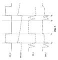
- FIG. 7 is a graph illustrating one or more operational parameters of the frequency limiting circuitry shown in FIG. 6 according to one embodiment of the present disclosure.
- FIG. 8 is a schematic illustrating details of the frequency limiting circuitry shown in FIG. 5 according to an additional embodiment of the present disclosure.
- FIG. 5 shows driver circuitry 40 according to one embodiment of the present disclosure.
- the driver circuitry 40 includes power converter circuitry 46 , switching control circuitry 48 , and frequency limiting circuitry 50 .
- the switching control circuitry 48 and the frequency limiting circuitry 50 may be referred to as frequency-limited switching control circuitry 51 , and the functionality thereof may be combined into a single component in some embodiments.
- the power converter circuitry 46 includes a bridge rectifier 52 , a power converter switching element Q_PC, a power converter transformer T_PC, and a power converter output capacitor C_PC.
- the bridge rectifier 52 includes a first rectifier diode D_R 1 with a cathode coupled to a first rectifier output node 54 and an anode coupled to a positive output of the AC power source 42 , a second rectifier diode D_R 2 with a cathode coupled to the first rectifier output node 54 and an anode coupled to a negative output of the AC power source 42 , a third rectifier diode D_R 3 with a cathode coupled to the positive output of the AC power source 42 and an anode coupled to a second rectifier output node 56 , and a fourth rectifier diode D_R 4 with a cathode coupled to the negative output of the AC power source 42 and an anode coupled to the second rectifier output node 56 .
- the power converter transformer T_PC includes a primary winding 58 coupled in series with the power converter switching element Q_PC between the first rectifier output node 54 and the second rectifier output node 56 . Further, the power converter transformer T_PC includes a secondary winding 60 coupled to a power converter diode D_PC and an auxiliary winding 62 coupled between the second rectifier output node 56 and the frequency limiting circuitry 50 .
- the power converter diode D_PC is coupled to the power converter output capacitor C_PC and the LED light source 44 .
- the switching control circuitry 48 is further coupled to the power converter switching element Q_PC.
- the frequency limiting circuitry 50 is coupled between the auxiliary winding 62 of the power converter transformer T_PC and the switching control circuitry 48 .
- the second rectifier output node 56 is typically used as ground for the switching control circuitry 48 .
- the power converter switching element Q_PS may be a metal-oxide-semiconductor field-effect transistor (MOSFET). Accordingly, a drain contact (D) of the power converter switching element Q_PS may be coupled to the primary winding 58 of the power converter transformer T_PC, a source contact (S) of the power converter switching element Q_PS may be coupled to the second rectifier output node 56 , and a gate contact (G) of the power converter switching element Q_PS may be coupled to the switching control circuitry 48 .
- MOSFET metal-oxide-semiconductor field-effect transistor
- an AC power supply signal AC_PS is received and rectified by the bridge rectifier 52 to provide a rectified input signal R_IS to the primary winding 58 of the power converter transformer T_PC.
- the power converter switching element Q_PC receives a switching control signal SW_C from the switching control circuitry 48 , which modulates the state of the power converter switching element Q_PC.
- the rectified input signal R_IS flows through the primary winding 58 of the power converter transformer T_PC, resulting in a storage of energy in the primary winding 58 via a build-up of magnetic flux.
- a voltage induced in the secondary winding 60 is negative, such that the power converter diode D_PC is reverse biased and the power converter output capacitor C_PC supplies power to the LED light source 44 .
- the power converter switching element Q_PC is in an OFF state, the magnetic field of the primary winding 58 begins to collapse, such that the primary winding 58 induces a positive voltage in the secondary winding 60 , thereby forward biasing the power converter diode D_PC and providing power to the power converter output capacitor C_PC and the LED light source 44 .
- the auxiliary winding 62 receives a similar signal to the secondary winding 60 , and thus is used to indirectly measure the characteristics of the primary winding 58 and/or the secondary winding 60 .
- Energy from the secondary winding 60 is placed across the power converter output capacitor C_PC where it is smoothed and delivered to the LED light source 44 as a regulated driver output signal R_OUT.
- a voltage signal from the auxiliary winding 62 is delivered to the frequency limiting circuitry 50 as a switching indicator signal SW_I, which is used by the frequency limiting circuitry 50 along with the switching control signal SW_C to provide a frequency limited switching trigger signal SW_T to the switching control circuitry 48 .
- the frequency limiting circuitry 50 may forward the switching indicator signal SW_I as the frequency limited switching trigger signal SW_T directly to the switching control circuitry 48 .
- the switching control circuitry 48 may be a pre-made critical or boundary conduction mode switching controller such as the L656X series of switching controllers made by STMicroelectronics, Inc. of Geneva, Switzerland. Accordingly, at frequencies of the switching control signal SW_C that are below a predetermined threshold, the switching control circuitry 48 may operate in a critical or boundary conduction mode.
- the frequency limiting circuitry 50 may alter one or more parameters of the switching indicator signal SW_I and forward the modified signal as the frequency limited switching trigger signal SW_T to the switching control circuitry 48 such that the overall frequency of the switching control signal SW_C is limited, as discussed in detail below.
- switching control circuitry 48 and the frequency limiting circuitry 50 are shown separately in FIG. 5 , the disclosure is not so limited. That is, the functionality of the switching control circuitry 48 and the frequency limiting circuitry 50 may be combined into a single module without departing from the principles described herein.
- FIG. 6 shows details of frequency limiting circuitry 50 according to one embodiment of the present disclosure.
- the frequency limiting circuitry 50 includes a first frequency limiting capacitor C_FL 1 and a first frequency limiting diode D_FL 1 coupled in series between a first input node 64 and a base contact (B) of a frequency limiting switching element Q_FL, such that an anode of the first frequency limiting diode D_FL 1 is coupled to the first frequency limiting capacitor C_FL 1 and a cathode of the first frequency limiting diode D_FL 1 is coupled to the base contact (B) of the frequency limiting switching element Q_FL.
- a second frequency limiting capacitor C_FL 2 is coupled between the base contact (B) of the frequency limiting switching element Q_FL and ground.
- a second frequency limiting diode D_FL 2 which may be a Zener diode, is coupled such that its anode is coupled to ground and its cathode is coupled to the first frequency limiting capacitor C_FL 1 and the anode of the first frequency limiting diode D_FL 1 .
- a first frequency limiting resistor R_FL 1 is coupled in parallel with the second frequency limiting capacitor C_FL 2 between the base contact (B) of the frequency limiting switching element Q_FL and ground.
- a collector contact (C) of the frequency limiting switching element Q_FL is coupled to a supply voltage VDD.
- An emitter contact (E) of the frequency limiting switching element Q_FL is coupled to an output node 66 via a second frequency limiting resistor R_FL 2 .
- a third frequency limiting capacitor C_FL 3 is coupled between the output node 66 and ground.
- a third frequency limiting diode D_FL 3 is coupled in series with a third frequency limiting resistor R_FL 3 between a second input node 68 and the emitter contact (E) of the frequency limiting switching element Q_FL, such that an anode of the third frequency limiting diode D_FL 3 is coupled to the second input node 68 and a cathode of the third frequency limiting diode D_FL 3 is coupled to the third frequency limiting resistor R_FL 3 .
- a fourth frequency limiting capacitor C_FL 4 and a fourth frequency limiting diode D_FL 4 are also coupled in series between the second input node 68 and the emitter contact (E) of the frequency limiting switching element Q_FL, such that an anode of the fourth frequency limiting diode D_FL 4 is coupled to the emitter contact (E) of the frequency limiting switching element Q_FL and a cathode of the fourth frequency limiting diode D_FL 4 is coupled to the fourth frequency limiting capacitor C_FL 4 .
- the cathode of the third frequency limiting diode D_FL 3 is coupled to the cathode of the fourth frequency limiting diode D_FL 4 .
- a fifth frequency limiting diode D_FL 5 includes an anode coupled to the cathode of the third frequency limiting diode D_FL 3 and the fourth frequency limiting diode D_FL 4 and a cathode coupled to the collector contact (C) of the frequency limiting switching element Q_FL.
- first frequency limiting diode D_FL 1 , the second frequency limiting diode D_FL 2 , the first frequency limiting capacitor C_FL 1 , the second frequency limiting capacitor C_FL 2 , the first frequency limiting resistor R_FL 1 , and the first frequency limiting switching element Q_FL may be referred to as clamp circuitry 70
- the third frequency limiting resistor R_FL 3 , the third frequency limiting diode D_FL 3 , the fourth frequency limiting diode D_FL 4 , the fifth frequency limiting diode D_FL 5 , and the fourth frequency limiting capacitor C_FL 4 are referred to as switching indicator signal SW_I monitoring circuitry 72 .
- clamp circuitry 70 and the switching indicator signal SW_I monitoring circuitry 72 are shown together in the frequency limiting circuitry 50 shown in FIG. 6 , they can also be used independently from one another. Further, while a number of specific components are shown in the clamp circuitry 70 and the switching indicator signal SW_I monitoring circuitry 72 , any number of different components arranged in a variety of ways may accomplish the functionality of the clamp circuitry 70 and the switching indicator signal SW_I monitoring circuitry 72 , all of which are contemplated herein.
- the frequency limiting circuitry 50 receives the switching control signal SW_C at the first input node 64 and the switching indicator signal SW_I at the second input node 68 , and outputs the frequency limiting switching trigger signal SW_T at the output node 66 .
- the second frequency limiting capacitor C_FL 2 is charged through the first frequency limiting capacitor C_FL 1 and the first frequency limiting diode D_FL 1 , thus bringing the voltage at the base contact (B) of the frequency limiting switching element Q_FL up to a portion of the voltage of the switching control signal SW_C defined as the voltage across the second frequency limiting diode D_FL 2 less the voltage across the first frequency limiting diode D_FL 1 .
- the voltage at the base contact (B) of the frequency limiting switching element Q_FL referred to as the decayed switching control signal SW_C, decays at a rate that may be controlled by the various values chosen for the first frequency limiting capacitor C_FL 1 , the second frequency limiting capacitor C_FL 2 , and the first frequency limiting resistor R_FL 1 , as shown in Equation (2):
- V SWCD ⁇ ⁇ 1 V SWCD ⁇ ⁇ 0 ⁇ e - t on R FL ⁇ ⁇ 1 ⁇ ( C FL ⁇ ⁇ 1 + C FL ⁇ ⁇ 2 ) ( 2 )
- V SWCD0 is the voltage of the decayed switching control signal SW_CD at the base contact (B) of the frequency limiting switching element Q_FL when the switching control signal SW_C initially transitions from low to high at time t 0
- V SWCD is the voltage of the decayed switching control signal SW_CD thereafter during the ramping decline of the decayed switching control signal SW_CD between time t 0 and t 1
- t on is the elapsed time that the switching control signal SW_C has been high (in other words, the on time of the switching control signal SW_C).
- the decayed switching control signal SW_CD begins to decay immediately after the switching control signal SW_C transitions from low to high, rather than being held high by the switching control signal SW_C, which results in the continuous ramping signal shown in FIG. 7 .
- the switching indicator signal SW_I becomes negative when the power converter switching element Q_PC is ON due to the primary winding 58 of the power converter transformer T_PC being shorted to ground
- the frequency limited switching trigger signal SW_T is held high by the base-to-emitter voltage of the frequency limiting switching element Q_FL.
- the second frequency limiting capacitor C_FL 2 is discharged through the first frequency limiting resistor R_FL 1 and the voltage across the first frequency limiting capacitor C_FL 1 is reset by the second frequency limiting diode D_FL 2 . Accordingly, the decayed switching control signal SW_CD continues to decline between time t 1 and t 3 .
- the switching control circuitry 48 will not transition the switching control signal from low to high until the switching trigger signal SW_T is below a predetermined triggering voltage V trig of the switching control circuitry 48 , as shown in Equations (3) and (4):
- the switching period is significantly less dependent on the on time of the switching control signal SW_C, especially when the value of C_FL 1 is smaller than C_FL 2 . Accordingly, the switching frequency variation is less than conventional solutions even during large changes in the input voltage or load level, which is beneficial to efficiency optimization and electromagnetic interference (EMI) filtering.
- EMI electromagnetic interference
- Switching losses in the driver circuitry 40 may be further mitigated via the use of valley switching. As shown in FIG. 7 , the switching indicator signal SW_I and the switching node voltages, such as the drain voltage of the power converter switching element Q_PC, ring when the power converter diode D_PC finishes conduction due to resonance. If the power converter switching element Q_PC is turned on at the valley point of these resonant voltages, the switching loss is minimized.
- the capability of the frequency limiting circuitry 50 to achieve valley switching can be improved by using the topology shown in FIG. 6 .
- the switching indicator signal SW_I is high while the power converter switching element Q_PC is OFF, due to the transfer of power from the primary winding 58 of the power converter transformer T_PC to the auxiliary windings.
- the frequency limited switching trigger signal SW_T is pulled high through the third frequency limiting diode D_FL 3 and the third frequency limiting resistor R_FL 3 , which prevents the switching control circuitry 48 from transitioning the switching control signal SW_C from high to low until the switching indicator signal SW_I rises above a predetermined threshold at time t 1 .
- the switching indicator signal SW_I begins to resonate.
- the frequency limited switching trigger signal SW_T follows the resonant pattern of the switching indicator signal, but is clamped by the base-to-emitter voltage of the frequency limiting switching element Q_FL as long as the decayed switching control signal SW_C is above the threshold voltage of the frequency limiting switching element Q_FL. Accordingly, the frequency limited switching trigger signal SW_T will not drop to a low enough level to trigger the switching control circuitry 48 to transition the switching control signal SW_C from high to low unless the switching indicator signal SW_I is decreasing while its value is low enough.
- the period in which the triggering occurs is only about a quarter of the time of a resonance period, which is a much narrower window for triggering than conventional solutions. Accordingly, valley switching of the driver circuitry 40 can be assured, which results in improvements in the efficiency of the driver circuitry 40 .
- FIG. 8 shows the frequency limiting circuitry 50 according to an additional embodiment of the present disclosure.
- the frequency limiting circuitry 50 shown in FIG. 8 is substantially similar to that shown in FIG. 7 , but further includes a frequency control adjustment transistor Q_FCA including a collector contact (C) coupled to the base contact (B) of the frequency limiting switching element Q_FL, an emitter contact (E) coupled to ground, and a base contact (B) configured to receive a frequency control adjustment signal FCA.
- a frequency control adjustment transistor Q_FCA including a collector contact (C) coupled to the base contact (B) of the frequency limiting switching element Q_FL, an emitter contact (E) coupled to ground, and a base contact (B) configured to receive a frequency control adjustment signal FCA.
Abstract
Description
where tS is the switching period of the switching control signal SW_C, ton is the ON time of the switching control signal SW_C, toff is the OFF time of the switching control signal SW_C, VBO is the initial voltage of the decayed switching control signal SW_CD at the base contact (B) of the minimum off-time switching element Q_MOT when the switching control signal SW_C transitions from low to high, and VBF is the final voltage of the decayed switching control signal SW_CD just before the next transition of the switching control signal SW_C from low to high again at time t3.
Claims (22)
Priority Applications (1)
| Application Number | Priority Date | Filing Date | Title |
|---|---|---|---|
| US14/558,214 US9654010B2 (en) | 2014-12-02 | 2014-12-02 | Power converter circuitry with switching frequency control circuitry |
Applications Claiming Priority (1)
| Application Number | Priority Date | Filing Date | Title |
|---|---|---|---|
| US14/558,214 US9654010B2 (en) | 2014-12-02 | 2014-12-02 | Power converter circuitry with switching frequency control circuitry |
Publications (2)
| Publication Number | Publication Date |
|---|---|
| US20160156269A1 US20160156269A1 (en) | 2016-06-02 |
| US9654010B2 true US9654010B2 (en) | 2017-05-16 |
Family
ID=56079813
Family Applications (1)
| Application Number | Title | Priority Date | Filing Date |
|---|---|---|---|
| US14/558,214 Active 2035-03-16 US9654010B2 (en) | 2014-12-02 | 2014-12-02 | Power converter circuitry with switching frequency control circuitry |
Country Status (1)
| Country | Link |
|---|---|
| US (1) | US9654010B2 (en) |
Families Citing this family (2)
| Publication number | Priority date | Publication date | Assignee | Title |
|---|---|---|---|---|
| JP6315336B2 (en) * | 2014-08-27 | 2018-04-25 | パナソニックIpマネジメント株式会社 | Lighting device and lighting apparatus |
| CN109976199A (en) * | 2017-12-27 | 2019-07-05 | 高权 | A kind of signal generation apparatus and the equipment with signal generation apparatus |
Citations (3)
| Publication number | Priority date | Publication date | Assignee | Title |
|---|---|---|---|---|
| US5841643A (en) * | 1997-10-01 | 1998-11-24 | Linear Technology Corporation | Method and apparatus for isolated flyback regulator control and load compensation |
| US7778051B2 (en) * | 2007-03-14 | 2010-08-17 | System General Corp. | Output current control circuit for power converter with a changeable switching frequency |
| US20150123565A1 (en) | 2013-11-05 | 2015-05-07 | Cree, Inc. | Minimum off time control systems and methods for switching power converters in discontinuous conduction mode |
-
2014
- 2014-12-02 US US14/558,214 patent/US9654010B2/en active Active
Patent Citations (3)
| Publication number | Priority date | Publication date | Assignee | Title |
|---|---|---|---|---|
| US5841643A (en) * | 1997-10-01 | 1998-11-24 | Linear Technology Corporation | Method and apparatus for isolated flyback regulator control and load compensation |
| US7778051B2 (en) * | 2007-03-14 | 2010-08-17 | System General Corp. | Output current control circuit for power converter with a changeable switching frequency |
| US20150123565A1 (en) | 2013-11-05 | 2015-05-07 | Cree, Inc. | Minimum off time control systems and methods for switching power converters in discontinuous conduction mode |
Also Published As
| Publication number | Publication date |
|---|---|
| US20160156269A1 (en) | 2016-06-02 |
Similar Documents
| Publication | Publication Date | Title |
|---|---|---|
| EP2512208B1 (en) | Solid-state lighting device and illumination fixture using the same | |
| US9844107B2 (en) | High efficiency driver circuitry for a solid state lighting fixture | |
| US8581518B2 (en) | Triac dimmer compatible switching mode power supply and method thereof | |
| US8569963B2 (en) | Cascade boost and inverting buck converter with independent control | |
| CN102076138B (en) | Electric supply input LED (Light Emitting Diode) constant current driver | |
| US8044600B2 (en) | Brightness-adjustable LED driving circuit | |
| EP2845301B1 (en) | Driver circuits for dimmable solid state lighting apparatus | |
| US9155151B2 (en) | LED dimming circuit for switched dimming | |
| KR101241470B1 (en) | Apparatus for controlling current | |
| US9232581B2 (en) | Output current compensation for jitter in input voltage for dimmable LED lamps | |
| US10271390B2 (en) | Solid-state lighting fixture with compound semiconductor driver circuitry | |
| JP2013118133A (en) | Lighting device and luminaire having the same | |
| US11903106B2 (en) | LED flashing circuit | |
| JP2013118134A (en) | Lighting device and luminaire having the same | |
| JP2013118131A (en) | Lighting device and luminaire having the same | |
| JP2013118132A (en) | Lighting device and luminaire having the same | |
| US9131570B2 (en) | Lighting device and luminaire | |
| US11388792B2 (en) | Control circuit, LED driving chip, LED driving system and LED driving method thereof | |
| US8508154B2 (en) | Lighting devices | |
| CN201860494U (en) | Light-emitting diode driving circuit with light modulating sequential control | |
| US9420645B2 (en) | Constant current control buck converter without current sense | |
| US9654010B2 (en) | Power converter circuitry with switching frequency control circuitry | |
| US9220138B1 (en) | Soft bleeder to remove step dimming | |
| WO2011050421A1 (en) | Improved method and apparatus for dimming a lighting device | |
| US9936545B2 (en) | LED voltage driver circuit |
Legal Events
| Date | Code | Title | Description |
|---|---|---|---|
| AS | Assignment |
Owner name: CREE, INC., NORTH CAROLINA Free format text: ASSIGNMENT OF ASSIGNORS INTEREST;ASSIGNOR:HU, QINGCONG;REEL/FRAME:034312/0058 Effective date: 20141202 |
|
| STCF | Information on status: patent grant |
Free format text: PATENTED CASE |
|
| AS | Assignment |
Owner name: IDEAL INDUSTRIES LIGHTING LLC, ILLINOIS Free format text: ASSIGNMENT OF ASSIGNORS INTEREST;ASSIGNOR:CREE, INC.;REEL/FRAME:049595/0001 Effective date: 20190513 |
|
| MAFP | Maintenance fee payment |
Free format text: PAYMENT OF MAINTENANCE FEE, 4TH YEAR, LARGE ENTITY (ORIGINAL EVENT CODE: M1551); ENTITY STATUS OF PATENT OWNER: LARGE ENTITY Year of fee payment: 4 |
|
| AS | Assignment |
Owner name: FGI WORLDWIDE LLC, NEW YORK Free format text: SECURITY INTEREST;ASSIGNOR:IDEAL INDUSTRIES LIGHTING LLC;REEL/FRAME:064897/0413 Effective date: 20230908 |