US9653408B2 - High-frequency package - Google Patents
High-frequency package Download PDFInfo
- Publication number
- US9653408B2 US9653408B2 US14/883,609 US201514883609A US9653408B2 US 9653408 B2 US9653408 B2 US 9653408B2 US 201514883609 A US201514883609 A US 201514883609A US 9653408 B2 US9653408 B2 US 9653408B2
- Authority
- US
- United States
- Prior art keywords
- die
- ground
- leads
- frequency package
- lead
- Prior art date
- Legal status (The legal status is an assumption and is not a legal conclusion. Google has not performed a legal analysis and makes no representation as to the accuracy of the status listed.)
- Active
Links
Images


Classifications
-
- H10W72/20—
-
- H—ELECTRICITY
- H01—ELECTRIC ELEMENTS
- H01L—SEMICONDUCTOR DEVICES NOT COVERED BY CLASS H10
- H01L23/00—Details of semiconductor or other solid state devices
- H01L23/552—Protection against radiation, e.g. light or electromagnetic waves
-
- H10W42/20—
-
- H—ELECTRICITY
- H01—ELECTRIC ELEMENTS
- H01L—SEMICONDUCTOR DEVICES NOT COVERED BY CLASS H10
- H01L23/00—Details of semiconductor or other solid state devices
- H01L23/48—Arrangements for conducting electric current to or from the solid state body in operation, e.g. leads, terminal arrangements ; Selection of materials therefor
- H01L23/488—Arrangements for conducting electric current to or from the solid state body in operation, e.g. leads, terminal arrangements ; Selection of materials therefor consisting of soldered or bonded constructions
- H01L23/495—Lead-frames or other flat leads
- H01L23/49503—Lead-frames or other flat leads characterised by the die pad
-
- H—ELECTRICITY
- H01—ELECTRIC ELEMENTS
- H01L—SEMICONDUCTOR DEVICES NOT COVERED BY CLASS H10
- H01L23/00—Details of semiconductor or other solid state devices
- H01L23/48—Arrangements for conducting electric current to or from the solid state body in operation, e.g. leads, terminal arrangements ; Selection of materials therefor
- H01L23/488—Arrangements for conducting electric current to or from the solid state body in operation, e.g. leads, terminal arrangements ; Selection of materials therefor consisting of soldered or bonded constructions
- H01L23/495—Lead-frames or other flat leads
- H01L23/49517—Additional leads
- H01L23/4952—Additional leads the additional leads being a bump or a wire
-
- H—ELECTRICITY
- H01—ELECTRIC ELEMENTS
- H01L—SEMICONDUCTOR DEVICES NOT COVERED BY CLASS H10
- H01L23/00—Details of semiconductor or other solid state devices
- H01L23/48—Arrangements for conducting electric current to or from the solid state body in operation, e.g. leads, terminal arrangements ; Selection of materials therefor
- H01L23/488—Arrangements for conducting electric current to or from the solid state body in operation, e.g. leads, terminal arrangements ; Selection of materials therefor consisting of soldered or bonded constructions
- H01L23/495—Lead-frames or other flat leads
- H01L23/49541—Geometry of the lead-frame
- H01L23/49548—Cross section geometry
-
- H—ELECTRICITY
- H01—ELECTRIC ELEMENTS
- H01L—SEMICONDUCTOR DEVICES NOT COVERED BY CLASS H10
- H01L23/00—Details of semiconductor or other solid state devices
- H01L23/58—Structural electrical arrangements for semiconductor devices not otherwise provided for, e.g. in combination with batteries
- H01L23/64—Impedance arrangements
- H01L23/66—High-frequency adaptations
-
- H—ELECTRICITY
- H01—ELECTRIC ELEMENTS
- H01L—SEMICONDUCTOR DEVICES NOT COVERED BY CLASS H10
- H01L24/00—Arrangements for connecting or disconnecting semiconductor or solid-state bodies; Methods or apparatus related thereto
- H01L24/01—Means for bonding being attached to, or being formed on, the surface to be connected, e.g. chip-to-package, die-attach, "first-level" interconnects; Manufacturing methods related thereto
- H01L24/42—Wire connectors; Manufacturing methods related thereto
- H01L24/47—Structure, shape, material or disposition of the wire connectors after the connecting process
- H01L24/49—Structure, shape, material or disposition of the wire connectors after the connecting process of a plurality of wire connectors
-
- H10W44/20—
-
- H10W70/411—
-
- H10W70/421—
-
- H10W70/424—
-
- H10W70/465—
-
- H10W70/68—
-
- H10W72/50—
-
- H—ELECTRICITY
- H01—ELECTRIC ELEMENTS
- H01L—SEMICONDUCTOR DEVICES NOT COVERED BY CLASS H10
- H01L2223/00—Details relating to semiconductor or other solid state devices covered by the group H01L23/00
- H01L2223/58—Structural electrical arrangements for semiconductor devices not otherwise provided for
- H01L2223/64—Impedance arrangements
- H01L2223/66—High-frequency adaptations
- H01L2223/6605—High-frequency electrical connections
- H01L2223/6611—Wire connections
-
- H—ELECTRICITY
- H01—ELECTRIC ELEMENTS
- H01L—SEMICONDUCTOR DEVICES NOT COVERED BY CLASS H10
- H01L2223/00—Details relating to semiconductor or other solid state devices covered by the group H01L23/00
- H01L2223/58—Structural electrical arrangements for semiconductor devices not otherwise provided for
- H01L2223/64—Impedance arrangements
- H01L2223/66—High-frequency adaptations
- H01L2223/6605—High-frequency electrical connections
- H01L2223/6638—Differential pair signal lines
-
- H—ELECTRICITY
- H01—ELECTRIC ELEMENTS
- H01L—SEMICONDUCTOR DEVICES NOT COVERED BY CLASS H10
- H01L2224/00—Indexing scheme for arrangements for connecting or disconnecting semiconductor or solid-state bodies and methods related thereto as covered by H01L24/00
- H01L2224/01—Means for bonding being attached to, or being formed on, the surface to be connected, e.g. chip-to-package, die-attach, "first-level" interconnects; Manufacturing methods related thereto
- H01L2224/42—Wire connectors; Manufacturing methods related thereto
- H01L2224/47—Structure, shape, material or disposition of the wire connectors after the connecting process
- H01L2224/48—Structure, shape, material or disposition of the wire connectors after the connecting process of an individual wire connector
- H01L2224/481—Disposition
- H01L2224/48151—Connecting between a semiconductor or solid-state body and an item not being a semiconductor or solid-state body, e.g. chip-to-substrate, chip-to-passive
- H01L2224/48221—Connecting between a semiconductor or solid-state body and an item not being a semiconductor or solid-state body, e.g. chip-to-substrate, chip-to-passive the body and the item being stacked
- H01L2224/48245—Connecting between a semiconductor or solid-state body and an item not being a semiconductor or solid-state body, e.g. chip-to-substrate, chip-to-passive the body and the item being stacked the item being metallic
- H01L2224/48247—Connecting between a semiconductor or solid-state body and an item not being a semiconductor or solid-state body, e.g. chip-to-substrate, chip-to-passive the body and the item being stacked the item being metallic connecting the wire to a bond pad of the item
-
- H—ELECTRICITY
- H01—ELECTRIC ELEMENTS
- H01L—SEMICONDUCTOR DEVICES NOT COVERED BY CLASS H10
- H01L2924/00—Indexing scheme for arrangements or methods for connecting or disconnecting semiconductor or solid-state bodies as covered by H01L24/00
- H01L2924/30—Technical effects
- H01L2924/301—Electrical effects
- H01L2924/30107—Inductance
-
- H10W44/206—
-
- H10W44/223—
-
- H10W72/884—
-
- H10W90/736—
-
- H10W90/756—
Definitions
- the present invention relates to a high-frequency package, and more particularly, to a high-frequency package capable of reducing high-frequency loss.
- Future mobile communication systems and satellite communication systems are usually required to operate at high frequencies.
- a traditional package is not customized for the high-frequency operation. Significant loss is caused at high frequencies, and degrades performance of the package.
- a wire bonding is performed to connect a die with leads via bonding wires. After the wires are bonded, a molding process is performed. Since the molding compound is usually made of a lossy material, an inductive effect is unavoidable and a serious loss at high frequencies is caused.
- FIGS. 1A-1C are schematic diagrams of a sectional side view, a top view and a bottom view of a package 10 in the prior art.
- a die 100 is bonded on a die pad 102 and connected to leads 104 via bonding wires 106 .
- the bonding wires 106 and the leads 104 would be covered by a molding compound after the molding process, and thus, inductance is formed around the bonding wires 106 and the leads 104 .
- a top surface of the die 100 is not coplanar with a top surface of the adjacent leads 104 , such that the bonding wires 106 is required to be sufficiently long, which causes a significant inductive effect and brings a serious loss at high frequencies.
- the present invention discloses a high-frequency package.
- the high-frequency package comprises a die; a plurality of leads; and a die pad; wherein a surface of the die pad is lower than top surfaces of the plurality of leads, the die is disposed on the die pad with the lower surface, such that a top surface of the die is substantially aligned with the top surfaces of the plurality of leads.
- FIGS. 1A-1C are schematic diagrams of a sectional side view, a top view, and a bottom view, respectively, of a package in the prior art.
- FIG. 2 is a schematic diagram of a circuit model
- FIGS. 3A-3C are schematic diagrams of a sectional side view, a top view, and a bottom view, respectively, of a high-frequency package according to an embodiment of the present invention.
- FIG. 4 is a frequency response diagram of transmission coefficient.
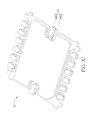
- FIG. 5 is a schematic diagram of a top view of a high-frequency package according to an embodiment of the present invention.
- FIG. 2 a schematic diagram of a circuit model of a package.
- an inductance L 1 represents an inductance around the bonding wires
- an inductance L 2 represents an inductance around the leads. Reducing either the inductance L 1 or the inductance L 2 (or the both) would alleviate transmission loss and enhance package performance at high frequencies.
- FIGS. 3A-3C are schematic diagrams of a sectional side view, a top view and a bottom view of a high-frequency package 30 according to an embodiment of the present invention, where FIG. 3A illustrates the sectional side view of the high-frequency package 30 along an A-A′ line (in FIG. 3B ).
- the high-frequency package 30 comprises a die 300 , a die pad 302 , leads 304 , and bonding wires 306 .
- the die 300 is disposed on the die pad 302 , and the bonding wires 306 connect the die 300 and the leads 304 .
- a notched area 308 with a notched depth DP is formed on the die pad 302 , such that a surface 328 of the die pad 302 is lower than top surfaces 324 of the leads 304 .
- a top surface 320 of the die 300 is substantially aligned (coplanar) with the top surfaces 324 of the leads 304 . In such a situation, lengths of the bonding wires 306 are shortened.
- the notched area 308 and the notched depth DP are configured to substantially align the top surface 320 of the die 300 with the top surfaces 324 of the leads 304 , such that lengths of the bonding wires 306 are shortened and the inductance L 1 of the high-frequency package 30 is reduced.
- the notched depth DP of the notched area 308 is designed to accommodate a thickness of the die 300 such that a difference in a horizontal level between the top surface 320 of the die 300 and the top surfaces 324 of the leads 304 is smaller than a specific value.
- the specific value is suggested to be 60% of the thickness of the die 300 . Since the lengths of the bonding wires 306 are shortened, the inductance L 1 around the bonding wires 306 is effectively reduced.
- the top surface of the die 300 is coplanar with the top surfaces of the leads 304 , and not limited thereto.
- the leads may be properly designed as transmission lines.
- a signal lead 346 on a side S 1 of the high-frequency package 30 , is connected to the die 300 and configured to deliver signals of the die 300 .
- the rest of leads on the side S 1 are integrated as a ground lead 344 .
- the ground lead 344 connected to a ground of the die 300 , occupies the entire side S 1 of the high-frequency package 30 .
- the signal lead 346 comprises an upper signal portion 3462 and a lower signal portion 3460 .
- the lower signal portion 3460 has a narrower area than the upper signal portion 3462 , such that the molding compound may have a better catching capability on the signal lead 346 after the molding process is performed.
- a slot is formed within the ground lead 344 , and the signal lead 346 is disposed within the slot.
- the ground lead 344 is separated from the signal lead 346 and surrounds the signal lead 346 .
- the ground lead 344 may comprise ground segments 340 , 342 .
- the ground segments 340 , 342 are connected to the ground of the die 300 and surround the signal lead 346 .
- the ground segments 340 , 342 are held at a same ground voltage level.
- a top surface of the ground lead 344 and a top surface of the signal lead 346 are at a same level.
- the ground lead 344 and the signal lead 346 form as a ground-signal-ground (GSG) structure, which further enhances the high-frequency performance of the high-frequency package 30 .
- the bonding wire 306 connecting the die 300 and the ground lead 344 is disposed between the bonding wires 306 connecting the die 300 and the signal lead 346 , which means that the bonding wires 306 also form as a GSG structure so as to enhance the high-frequency performance of the high-frequency package 30 .
- the high-frequency performance of the high-frequency package 30 may be evaluated by a frequency response diagram of insertion loss (i.e., the scattering parameter S 21 ) of the package 10 and the high-frequency package 30 , as shown in FIG. 4 .
- a dashed line represents the frequency response of insertion loss of the package 10
- a solid line represents that of the high-frequency package 30 .
- a characteristic frequency (at which the insertion loss is 1 dB) of the package 10 is only 26 GHz.
- a characteristic frequency of the high-frequency package 30 is improved to approach 31 GHz (more than 30 GHz).
- ripples in frequency response under the characteristic frequency of the high-frequency package 30 are minor than the package 10 , which benefits an operation of the high-frequency package 30 .
- the embodiments stated in the above are utilized for illustrating the concept of the present invention. Those skilled in the art may make modifications and alternations accordingly, and not limited herein.
- methods of forming the notched area are not limited.
- the notched area is formed by either topside etching or backside etching, and not limited herein.
- the signal lead and the ground lead may be realized using microstrip line or coplanar waveguide, and not limited herein.
- the die pad 302 is not limited to having the notched area 308 formed therein.
- the die pad may be downset. As long as the surface 328 of the die pad is lower than the top surfaces 324 of the leads 304 such that the top surface 320 of the die 300 is substantially aligned (coplanar) with the top surfaces 324 of the leads 304 , the requirements of the present invention is satisfied.
- a shape of the signal lead is not limited.
- the shape of the signal lead may be modified according to the practical situation.
- FIG. 5 is a schematic diagram of a top view of a high-frequency package 50 according to an embodiment of the present invention.
- a signal lead 546 of the high-frequency package 50 may comprise protrusions 5462 , 5464 .
- the protrusions 5462 , 5464 protrude from a central portion 5460 of the signal lead 546 .
- the protrusions 5462 , 5464 may form a capacitance effect of transmission line, which may further enhance the high-frequency performance of the high-frequency package.
- the high-frequency package of the present invention utilizes the notched area formed on the die pad to align the top surface of the die with the top surface of the leads, so as to shorten the lengths of the bonding wires.
- the signal lead and the ground lead are form as the GSG structure of transmission line, which further improves the high-frequency performance of the high-frequency package.
Landscapes
- Physics & Mathematics (AREA)
- Power Engineering (AREA)
- Engineering & Computer Science (AREA)
- Computer Hardware Design (AREA)
- Microelectronics & Electronic Packaging (AREA)
- General Physics & Mathematics (AREA)
- Condensed Matter Physics & Semiconductors (AREA)
- Lead Frames For Integrated Circuits (AREA)
- Health & Medical Sciences (AREA)
- Electromagnetism (AREA)
- Toxicology (AREA)
- Geometry (AREA)
- Waveguide Connection Structure (AREA)
Abstract
Description
Claims (8)
Priority Applications (3)
| Application Number | Priority Date | Filing Date | Title |
|---|---|---|---|
| US14/883,609 US9653408B2 (en) | 2015-08-13 | 2015-10-14 | High-frequency package |
| TW105102435A TWI627713B (en) | 2015-08-13 | 2016-01-27 | High frequency package structure |
| CN201610069349.XA CN106449528B (en) | 2015-08-13 | 2016-02-01 | High-frequency packaging structure |
Applications Claiming Priority (2)
| Application Number | Priority Date | Filing Date | Title |
|---|---|---|---|
| US201562204972P | 2015-08-13 | 2015-08-13 | |
| US14/883,609 US9653408B2 (en) | 2015-08-13 | 2015-10-14 | High-frequency package |
Publications (2)
| Publication Number | Publication Date |
|---|---|
| US20170047299A1 US20170047299A1 (en) | 2017-02-16 |
| US9653408B2 true US9653408B2 (en) | 2017-05-16 |
Family
ID=57400044
Family Applications (3)
| Application Number | Title | Priority Date | Filing Date |
|---|---|---|---|
| US14/882,412 Active US9515032B1 (en) | 2015-08-13 | 2015-10-13 | High-frequency package |
| US14/883,609 Active US9653408B2 (en) | 2015-08-13 | 2015-10-14 | High-frequency package |
| US14/883,635 Active US9673152B2 (en) | 2015-08-13 | 2015-10-15 | High-frequency package |
Family Applications Before (1)
| Application Number | Title | Priority Date | Filing Date |
|---|---|---|---|
| US14/882,412 Active US9515032B1 (en) | 2015-08-13 | 2015-10-13 | High-frequency package |
Family Applications After (1)
| Application Number | Title | Priority Date | Filing Date |
|---|---|---|---|
| US14/883,635 Active US9673152B2 (en) | 2015-08-13 | 2015-10-15 | High-frequency package |
Country Status (3)
| Country | Link |
|---|---|
| US (3) | US9515032B1 (en) |
| CN (3) | CN106449582B (en) |
| TW (3) | TWI571991B (en) |
Cited By (1)
| Publication number | Priority date | Publication date | Assignee | Title |
|---|---|---|---|---|
| US10665555B2 (en) | 2018-02-07 | 2020-05-26 | Win Semiconductors Corp. | Transition structure and high-frequency package |
Citations (28)
| Publication number | Priority date | Publication date | Assignee | Title |
|---|---|---|---|---|
| US5057805A (en) | 1990-05-16 | 1991-10-15 | Mitsubishi Denki Kabushiki Kaisha | Microwave semiconductor device |
| US5677570A (en) * | 1995-02-17 | 1997-10-14 | Hitachi, Ltd. | Semiconductor integrated circuit devices for high-speed or high frequency |
| US5808325A (en) * | 1996-06-28 | 1998-09-15 | Motorola, Inc. | Optical transmitter package assembly including lead frame having exposed flange with key |
| US5932927A (en) | 1996-07-24 | 1999-08-03 | Nec Corporation | High-frequency device package |
| US6239669B1 (en) | 1997-04-25 | 2001-05-29 | Kyocera Corporation | High frequency package |
| US20010005039A1 (en) * | 1997-12-22 | 2001-06-28 | Russell Ernest J. | Method and apparatus for delivering electrical power to a semiconductor die |
| US20030151113A1 (en) * | 2002-02-14 | 2003-08-14 | Rohm Co., Ltd. | Semiconductor device |
| US6642808B2 (en) | 2000-05-30 | 2003-11-04 | Kyocera Corporation | High frequency package, wiring board, and high frequency module having a cyclically varying transmission characteristic |
| US6828658B2 (en) | 2002-05-09 | 2004-12-07 | M/A-Com, Inc. | Package for integrated circuit with internal matching |
| TW200504964A (en) | 2003-07-29 | 2005-02-01 | Advanced Semiconductor Eng | Semiconductor chip package and method for making the same |
| US20050051877A1 (en) * | 2003-09-10 | 2005-03-10 | Siliconware Precision Industries Co., Ltd. | Semiconductor package having high quantity of I/O connections and method for fabricating the same |
| TW200522318A (en) | 2003-12-31 | 2005-07-01 | Advanced Semiconductor Eng | Leadless package |
| US20050184825A1 (en) | 2004-02-19 | 2005-08-25 | Ekrem Oran | RF package |
| US6936921B2 (en) | 2002-11-11 | 2005-08-30 | Kyocera Corporation | High-frequency package |
| TW200625585A (en) | 2005-01-06 | 2006-07-16 | Via Tech Inc | A wire-bonding type lead frame package |
| US7211887B2 (en) | 2004-11-30 | 2007-05-01 | M/A-Com, Inc. | connection arrangement for micro lead frame plastic packages |
| US7489022B2 (en) | 2005-08-02 | 2009-02-10 | Viasat, Inc. | Radio frequency over-molded leadframe package |
| US20090159320A1 (en) * | 2007-12-19 | 2009-06-25 | Bridgewave Communications, Inc. | Low Cost High Frequency Device Package and Methods |
| TW200939416A (en) | 2008-03-14 | 2009-09-16 | Advanced Semiconductor Eng | Semiconductor package and process thereof and surface-mounted semiconductor package |
| TW201010036A (en) | 2008-08-21 | 2010-03-01 | Advanced Semiconductor Eng | Advanced quad flat non-leaded package structure and manufacturing method thereof |
| US8044496B2 (en) | 2008-05-19 | 2011-10-25 | Mediatek Inc. | QFN semiconductor package |
| US20120051000A1 (en) | 2010-08-31 | 2012-03-01 | Viasat, Inc. | Leadframe package with integrated partial waveguide interface |
| US20120208324A1 (en) * | 2011-02-14 | 2012-08-16 | Renesas Electronics Corporation | Manufacturing method of semiconductor device |
| US20120218729A1 (en) * | 2011-02-28 | 2012-08-30 | Rf Micro Devices, Inc. | Microshield on standard qfn package |
| TW201338114A (en) | 2012-03-15 | 2013-09-16 | 日月光半導體製造股份有限公司 | Pin extended semiconductor package and method of manufacturing same |
| US20140036471A1 (en) | 2012-08-06 | 2014-02-06 | Cindy Yuen | Thin Leadframe QFN Package Design of RF Front-Ends for Mobile Wireless Communication |
| US8912664B1 (en) | 2007-08-29 | 2014-12-16 | Marvell International Ltd. | Leadless multi-chip module structure |
| US8999755B1 (en) | 2009-05-06 | 2015-04-07 | Marvell International Ltd. | Etched hybrid die package |
Family Cites Families (4)
| Publication number | Priority date | Publication date | Assignee | Title |
|---|---|---|---|---|
| JPH0621319A (en) * | 1992-06-30 | 1994-01-28 | Nec Corp | Lead frame for semiconductor device |
| JPH10247717A (en) * | 1997-03-04 | 1998-09-14 | Matsushita Electron Corp | Semiconductor device |
| TWI224386B (en) * | 2003-07-22 | 2004-11-21 | Via Tech Inc | Multi-row wire bonding structure for high frequency integrated circuit |
| JP6015963B2 (en) * | 2011-12-22 | 2016-11-02 | パナソニックIpマネジメント株式会社 | Semiconductor package, manufacturing method thereof and mold |
-
2015
- 2015-10-13 US US14/882,412 patent/US9515032B1/en active Active
- 2015-10-14 US US14/883,609 patent/US9653408B2/en active Active
- 2015-10-15 US US14/883,635 patent/US9673152B2/en active Active
-
2016
- 2016-01-21 TW TW105101822A patent/TWI571991B/en not_active IP Right Cessation
- 2016-01-25 CN CN201610048246.5A patent/CN106449582B/en not_active Expired - Fee Related
- 2016-01-27 TW TW105102436A patent/TWI585909B/en active
- 2016-01-27 TW TW105102435A patent/TWI627713B/en active
- 2016-02-01 CN CN201610069864.8A patent/CN106449577A/en active Pending
- 2016-02-01 CN CN201610069349.XA patent/CN106449528B/en not_active Expired - Fee Related
Patent Citations (31)
| Publication number | Priority date | Publication date | Assignee | Title |
|---|---|---|---|---|
| US5057805A (en) | 1990-05-16 | 1991-10-15 | Mitsubishi Denki Kabushiki Kaisha | Microwave semiconductor device |
| US5677570A (en) * | 1995-02-17 | 1997-10-14 | Hitachi, Ltd. | Semiconductor integrated circuit devices for high-speed or high frequency |
| US5808325A (en) * | 1996-06-28 | 1998-09-15 | Motorola, Inc. | Optical transmitter package assembly including lead frame having exposed flange with key |
| US5932927A (en) | 1996-07-24 | 1999-08-03 | Nec Corporation | High-frequency device package |
| US6239669B1 (en) | 1997-04-25 | 2001-05-29 | Kyocera Corporation | High frequency package |
| US20010005039A1 (en) * | 1997-12-22 | 2001-06-28 | Russell Ernest J. | Method and apparatus for delivering electrical power to a semiconductor die |
| US6642808B2 (en) | 2000-05-30 | 2003-11-04 | Kyocera Corporation | High frequency package, wiring board, and high frequency module having a cyclically varying transmission characteristic |
| US20030151113A1 (en) * | 2002-02-14 | 2003-08-14 | Rohm Co., Ltd. | Semiconductor device |
| US6661101B2 (en) | 2002-02-14 | 2003-12-09 | Rohm Co., Ltd. | Semiconductor device |
| US6828658B2 (en) | 2002-05-09 | 2004-12-07 | M/A-Com, Inc. | Package for integrated circuit with internal matching |
| US6936921B2 (en) | 2002-11-11 | 2005-08-30 | Kyocera Corporation | High-frequency package |
| TW200504964A (en) | 2003-07-29 | 2005-02-01 | Advanced Semiconductor Eng | Semiconductor chip package and method for making the same |
| US20050051877A1 (en) * | 2003-09-10 | 2005-03-10 | Siliconware Precision Industries Co., Ltd. | Semiconductor package having high quantity of I/O connections and method for fabricating the same |
| TW200522318A (en) | 2003-12-31 | 2005-07-01 | Advanced Semiconductor Eng | Leadless package |
| US20050184825A1 (en) | 2004-02-19 | 2005-08-25 | Ekrem Oran | RF package |
| US7187256B2 (en) * | 2004-02-19 | 2007-03-06 | Hittite Microwave Corporation | RF package |
| US7211887B2 (en) | 2004-11-30 | 2007-05-01 | M/A-Com, Inc. | connection arrangement for micro lead frame plastic packages |
| TW200625585A (en) | 2005-01-06 | 2006-07-16 | Via Tech Inc | A wire-bonding type lead frame package |
| US7489022B2 (en) | 2005-08-02 | 2009-02-10 | Viasat, Inc. | Radio frequency over-molded leadframe package |
| US8912664B1 (en) | 2007-08-29 | 2014-12-16 | Marvell International Ltd. | Leadless multi-chip module structure |
| US20090159320A1 (en) * | 2007-12-19 | 2009-06-25 | Bridgewave Communications, Inc. | Low Cost High Frequency Device Package and Methods |
| TW200939416A (en) | 2008-03-14 | 2009-09-16 | Advanced Semiconductor Eng | Semiconductor package and process thereof and surface-mounted semiconductor package |
| US8044496B2 (en) | 2008-05-19 | 2011-10-25 | Mediatek Inc. | QFN semiconductor package |
| TW201010036A (en) | 2008-08-21 | 2010-03-01 | Advanced Semiconductor Eng | Advanced quad flat non-leaded package structure and manufacturing method thereof |
| US8999755B1 (en) | 2009-05-06 | 2015-04-07 | Marvell International Ltd. | Etched hybrid die package |
| US20120051000A1 (en) | 2010-08-31 | 2012-03-01 | Viasat, Inc. | Leadframe package with integrated partial waveguide interface |
| US20120208324A1 (en) * | 2011-02-14 | 2012-08-16 | Renesas Electronics Corporation | Manufacturing method of semiconductor device |
| US8987063B2 (en) | 2011-02-14 | 2015-03-24 | Renesas Electronics Corporation | Manufacturing method of semiconductor device |
| US20120218729A1 (en) * | 2011-02-28 | 2012-08-30 | Rf Micro Devices, Inc. | Microshield on standard qfn package |
| TW201338114A (en) | 2012-03-15 | 2013-09-16 | 日月光半導體製造股份有限公司 | Pin extended semiconductor package and method of manufacturing same |
| US20140036471A1 (en) | 2012-08-06 | 2014-02-06 | Cindy Yuen | Thin Leadframe QFN Package Design of RF Front-Ends for Mobile Wireless Communication |
Cited By (1)
| Publication number | Priority date | Publication date | Assignee | Title |
|---|---|---|---|---|
| US10665555B2 (en) | 2018-02-07 | 2020-05-26 | Win Semiconductors Corp. | Transition structure and high-frequency package |
Also Published As
| Publication number | Publication date |
|---|---|
| TW201707161A (en) | 2017-02-16 |
| TWI585909B (en) | 2017-06-01 |
| TWI571991B (en) | 2017-02-21 |
| TW201707169A (en) | 2017-02-16 |
| CN106449528A (en) | 2017-02-22 |
| US9673152B2 (en) | 2017-06-06 |
| US20170047299A1 (en) | 2017-02-16 |
| CN106449582B (en) | 2018-11-02 |
| CN106449582A (en) | 2017-02-22 |
| US9515032B1 (en) | 2016-12-06 |
| TWI627713B (en) | 2018-06-21 |
| CN106449577A (en) | 2017-02-22 |
| TW201707154A (en) | 2017-02-16 |
| US20170047292A1 (en) | 2017-02-16 |
| CN106449528B (en) | 2019-05-07 |
Similar Documents
| Publication | Publication Date | Title |
|---|---|---|
| JP5377778B2 (en) | Electromagnetic resonance coupler | |
| US20180301428A1 (en) | Millimeter wave integrated circuit with ball grid array package including transmit and receive channels | |
| US7087993B2 (en) | Chip package and electrical connection structure between chip and substrate | |
| US20160343653A1 (en) | Package Structure and Three Dimensional Package Structure | |
| US20180108965A1 (en) | Radio Frequency Device | |
| US9640857B2 (en) | Communication module | |
| US9653408B2 (en) | High-frequency package | |
| EP2509105A1 (en) | Semiconductor device having improved performance for high RF output powers | |
| US9431362B2 (en) | Semiconductor module | |
| US20160240494A1 (en) | Rf package and manufacturing method thereof | |
| KR101823232B1 (en) | Common mode filter | |
| CN110600431A (en) | Integrated circuit package and method of forming the same | |
| CN204885153U (en) | Integrated circuit packaging body | |
| US11342260B2 (en) | Power flat no-lead package | |
| US8217496B2 (en) | Internal matching transistor | |
| CN111342788B (en) | Structure and method for improving suppression or isolation of electronic devices in high frequency bands | |
| JP5616839B2 (en) | High frequency equipment | |
| US10665555B2 (en) | Transition structure and high-frequency package | |
| CN104392974A (en) | Terminal and internal chip configuration structure of QFN (Quad Flat No-Lead) package high-frequency integrated circuit | |
| US20120106120A1 (en) | Transmission line for electronic circuits | |
| US20220285242A1 (en) | Semiconductor device | |
| US20150214161A1 (en) | Semiconductor structure | |
| KR20250082214A (en) | Antenna apparatus having a vertically stacked folded dipole | |
| JP2013016666A (en) | Semiconductor device | |
| JP2015042001A (en) | Semiconductor device |
Legal Events
| Date | Code | Title | Description |
|---|---|---|---|
| AS | Assignment |
Owner name: WIN SEMICONDUCTORS CORP., TAIWAN Free format text: ASSIGNMENT OF ASSIGNORS INTEREST;ASSIGNORS:HUANG, CHIH-WEN;CHEN, YU-CHIAO;REEL/FRAME:036795/0473 Effective date: 20150828 |
|
| STCF | Information on status: patent grant |
Free format text: PATENTED CASE |
|
| MAFP | Maintenance fee payment |
Free format text: PAYMENT OF MAINTENANCE FEE, 4TH YEAR, LARGE ENTITY (ORIGINAL EVENT CODE: M1551); ENTITY STATUS OF PATENT OWNER: LARGE ENTITY Year of fee payment: 4 |
|
| MAFP | Maintenance fee payment |
Free format text: PAYMENT OF MAINTENANCE FEE, 8TH YEAR, LARGE ENTITY (ORIGINAL EVENT CODE: M1552); ENTITY STATUS OF PATENT OWNER: LARGE ENTITY Year of fee payment: 8 |