US9652155B2 - Computer system, cash data management method, and computer - Google Patents
Computer system, cash data management method, and computer Download PDFInfo
- Publication number
- US9652155B2 US9652155B2 US14/642,873 US201514642873A US9652155B2 US 9652155 B2 US9652155 B2 US 9652155B2 US 201514642873 A US201514642873 A US 201514642873A US 9652155 B2 US9652155 B2 US 9652155B2
- Authority
- US
- United States
- Prior art keywords
- request
- data
- cache
- server
- monitoring
- Prior art date
- Legal status (The legal status is an assumption and is not a legal conclusion. Google has not performed a legal analysis and makes no representation as to the accuracy of the status listed.)
- Active, expires
Links
Images


Classifications
-
- H—ELECTRICITY
- H04—ELECTRIC COMMUNICATION TECHNIQUE
- H04L—TRANSMISSION OF DIGITAL INFORMATION, e.g. TELEGRAPHIC COMMUNICATION
- H04L67/00—Network arrangements or protocols for supporting network services or applications
- H04L67/50—Network services
- H04L67/56—Provisioning of proxy services
- H04L67/568—Storing data temporarily at an intermediate stage, e.g. caching
-
- G—PHYSICS
- G06—COMPUTING OR CALCULATING; COUNTING
- G06F—ELECTRIC DIGITAL DATA PROCESSING
- G06F3/00—Input arrangements for transferring data to be processed into a form capable of being handled by the computer; Output arrangements for transferring data from processing unit to output unit, e.g. interface arrangements
- G06F3/06—Digital input from, or digital output to, record carriers, e.g. RAID, emulated record carriers or networked record carriers
- G06F3/0601—Interfaces specially adapted for storage systems
- G06F3/0602—Interfaces specially adapted for storage systems specifically adapted to achieve a particular effect
- G06F3/061—Improving I/O performance
-
- G—PHYSICS
- G06—COMPUTING OR CALCULATING; COUNTING
- G06F—ELECTRIC DIGITAL DATA PROCESSING
- G06F3/00—Input arrangements for transferring data to be processed into a form capable of being handled by the computer; Output arrangements for transferring data from processing unit to output unit, e.g. interface arrangements
- G06F3/06—Digital input from, or digital output to, record carriers, e.g. RAID, emulated record carriers or networked record carriers
- G06F3/0601—Interfaces specially adapted for storage systems
- G06F3/0628—Interfaces specially adapted for storage systems making use of a particular technique
- G06F3/0653—Monitoring storage devices or systems
-
- G—PHYSICS
- G06—COMPUTING OR CALCULATING; COUNTING
- G06F—ELECTRIC DIGITAL DATA PROCESSING
- G06F3/00—Input arrangements for transferring data to be processed into a form capable of being handled by the computer; Output arrangements for transferring data from processing unit to output unit, e.g. interface arrangements
- G06F3/06—Digital input from, or digital output to, record carriers, e.g. RAID, emulated record carriers or networked record carriers
- G06F3/0601—Interfaces specially adapted for storage systems
- G06F3/0628—Interfaces specially adapted for storage systems making use of a particular technique
- G06F3/0655—Vertical data movement, i.e. input-output transfer; data movement between one or more hosts and one or more storage devices
- G06F3/0656—Data buffering arrangements
-
- G—PHYSICS
- G06—COMPUTING OR CALCULATING; COUNTING
- G06F—ELECTRIC DIGITAL DATA PROCESSING
- G06F3/00—Input arrangements for transferring data to be processed into a form capable of being handled by the computer; Output arrangements for transferring data from processing unit to output unit, e.g. interface arrangements
- G06F3/06—Digital input from, or digital output to, record carriers, e.g. RAID, emulated record carriers or networked record carriers
- G06F3/0601—Interfaces specially adapted for storage systems
- G06F3/0668—Interfaces specially adapted for storage systems adopting a particular infrastructure
- G06F3/0671—In-line storage system
- G06F3/0683—Plurality of storage devices
- G06F3/0685—Hybrid storage combining heterogeneous device types, e.g. hierarchical storage, hybrid arrays
-
- G—PHYSICS
- G06—COMPUTING OR CALCULATING; COUNTING
- G06F—ELECTRIC DIGITAL DATA PROCESSING
- G06F3/00—Input arrangements for transferring data to be processed into a form capable of being handled by the computer; Output arrangements for transferring data from processing unit to output unit, e.g. interface arrangements
- G06F3/06—Digital input from, or digital output to, record carriers, e.g. RAID, emulated record carriers or networked record carriers
- G06F3/0601—Interfaces specially adapted for storage systems
- G06F3/0668—Interfaces specially adapted for storage systems adopting a particular infrastructure
- G06F3/0671—In-line storage system
- G06F3/0683—Plurality of storage devices
- G06F3/0689—Disk arrays, e.g. RAID, JBOD
-
- H04L67/2842—
-
- H04L67/2852—
-
- H—ELECTRICITY
- H04—ELECTRIC COMMUNICATION TECHNIQUE
- H04L—TRANSMISSION OF DIGITAL INFORMATION, e.g. TELEGRAPHIC COMMUNICATION
- H04L67/00—Network arrangements or protocols for supporting network services or applications
- H04L67/50—Network services
- H04L67/56—Provisioning of proxy services
- H04L67/568—Storing data temporarily at an intermediate stage, e.g. caching
- H04L67/5682—Policies or rules for updating, deleting or replacing the stored data
Definitions
- This invention relates to control of an arrangement of data on a cache of a service server.
- nonvolatile memories such as a flash memory are used in various electronic devices. Unlike a hard disk drive (HDD), the nonvolatile memory does not involve a mechanical operation, and enables faster access than the HDD.
- HDD hard disk drive
- Nonvolatile memories are also used in enterprise applications such as a server and a storage system that need fast data access.
- nonvolatile memories mountable in servers become inexpensive, and are thus becoming popular.
- a technology for a storage system in which a hierarchical storage area is constructed from a storage medium with high an access performance and a storage medium with low access performance, and the storage area for storing data is changed based on access characteristics of the data.
- a hierarchical storage area is constructed from a storage medium with high an access performance and a storage medium with low access performance, and the storage area for storing data is changed based on access characteristics of the data.
- the cache driver controls data to be stored in the flash memory based on a cache control algorithm such as LRU.
- the cache driver can control data actually accessed, namely, data accessed within a short period of time.
- the cache driver cannot control data while considering an access characteristic of an application and a schedule of a service.
- an object of this invention is to provide a computer system for realizing control of cache data considering access characteristics of an application and a schedule of a service.
- a computer system comprising: a service server on which an application for carrying out predetermined processing operates; a storage server for storing data used by the application; and a management server for managing the service server and the storage server.
- the service server includes a first processor, a first memory coupled to the first processor, a cache device which is coupled to the first processor, and to which a server cache for temporarily storing data is set, and a first interface coupled to the first processor for coupling to another apparatus.
- the storage server includes a second processor, a second memory coupled to the second processor, a second interface coupled to the second processor for coupling to another apparatus, and a plurality of storage devices.
- the management server includes a third processor, a third memory coupled to the third processor, and a third interface coupled to the third processor for coupling to another apparatus.
- the service server has an operating system for controlling the service server, the operating system including a cache driver for controlling the server cache; and an I/O request monitoring unit for monitoring an I/O request issued by the application, and issuing a dummy I/O request for controlling an arrangement of data in the server cache in a case where a predetermined condition is satisfied.
- the management server has a cache optimization unit for generating a control policy for issuing the dummy I/O request, and setting the control policy to the I/O request monitoring unit.
- the cache optimization unit being configured to instruct the service server to carry out processing.
- the I/O request monitoring unit being configured to: monitor the I/O request issued by the application operating on the service server; and transmit monitoring information including an address of data of an access destination included in the I/O request and an identifier of an application that has issued the I/O request to the cache optimization unit in a case where the I/O request is detected, the cache optimization unit is configured to analyze the monitoring information, thereby generating the control policy.
- the I/O request monitoring unit independently of the cache control algorithm of the cache driver, issues the dummy I/O request based on the control policy generated by the cache optimization unit analyzing the monitoring information, thereby optimizing the arrangement of data in the server cache. Consequently, a processing performance of the application can be increased.
- FIG. 1 is a block diagram illustrating the outline of this invention
- FIG. 2 is a block diagram illustrating a configuration example of a management server according to a first embodiment of this invention
- FIG. 3 is a block diagram illustrating a configuration example of a service server according to the first embodiment of this invention
- FIG. 4 is a block diagram illustrating a configuration example of a storage server according to the first embodiment of this invention.
- FIG. 5 is an explanatory diagram showing an example of control information according to the first embodiment of this invention.
- FIG. 6 is a flowchart illustrating an analysis processing for an access characteristics carried out by a cache optimization unit according to the first embodiment of this invention
- FIG. 7 is a flowchart illustrating control information generation processing carried out by the cache optimization unit according to the first embodiment of this invention.
- FIG. 8 is a flowchart illustrating I/O request monitoring processing carried out by an I/O request monitoring unit according to the first embodiment of this invention.
- FIG. 1 is a block diagram illustrating the outline of this invention.
- a computer system illustrated in FIG. 1 includes a management server 100 , a service server 200 , and a storage server 300 . It should be noted that the number of the service servers 200 and the number of the storage servers 300 may each be two or more.
- the management server 100 is coupled to the service server 200 and the storage server 300 via a management network 400 .
- the service server 200 is coupled to the storage server 300 via a service network 410 . It should be noted that, if the computer system includes a plurality of the service servers 200 , the respective service servers 200 may be coupled to the storage server 300 via service networks different from one another.
- the service server 200 is a computer for carrying out an arbitrary service, and at least one application 230 operates on the service server 200 .
- the service server 200 includes a cache driver 213 and a server cache 240 .
- the server cache 240 is a storage area for temporarily storing data.
- the cache driver 213 is a module for controlling data stored in the server cache 240 based on an I/O request issued by the application 230 .
- the storage server 300 is a computer for providing a storage area used by the application 230 operating on the service server 200 .
- the storage server 300 includes a storage area management OS 310 for managing the storage area.
- the storage server 300 includes a storage cache 320 and a plurality of tiered storage areas 330 .
- the storage cache 320 is a storage area for temporarily storing data.
- the tiered storage area 330 is a storage area to be provided to the service server 200 .
- the storage server 300 includes two tiered storage areas 330 - 1 and 330 - 2 different from each other in an access performance.
- the storage server 300 provides at least one of the tiered storage areas 330 - 1 and 330 - 2 to the service server 200 .
- data used by the application 230 is stored in at least one of the tiered storage areas 330 - 1 and 330 - 2 . Moreover, data accessed by the application 230 is temporarily stored in the storage cache 320 .
- the data used by the application 230 is hereinafter also referred to as application data.
- the management server 100 analyzes access characteristics of the application 230 on the service server 200 , and then generates control information (control policy) for controlling an arrangement of the application data in the server cache 240 .
- the arrangement of the application data in the server cache 240 means storing the application data in the server cache 240 and ejection of the application data stored in the server cache. Specifically, the following processing is carried out.
- the management server 100 instructs the service server 200 to carry out a service in order to analyze the access characteristics of the application 230 .
- the service includes at least one piece of processing.
- a service such as a batch operation includes data collection processing and data analysis processing.
- the applications 230 for carrying out the respective pieces of processing may be different from one another.
- an I/O request monitoring unit 220 of this service server 200 monitors an I/O request issued by the application 230 .
- the I/O request monitoring unit 220 generates I/O monitoring information.
- the I/O request monitoring unit 220 transmits the generated I/O monitoring information to a cache optimization unit 110 of the management server 100 .
- the I/O request monitoring unit 220 may transmit the I/O monitoring information each time an I/O request is detected, or may transmit the I/O monitoring information after a predetermined number of I/O requests have been detected.
- the I/O request monitoring unit 220 may periodically transmit the I/O monitoring information.
- the cache optimization unit 110 analyzes the access characteristics of the application 230 based on the I/O monitoring information.
- the cache optimization unit 110 generates control information to be set to the service server 200 based on an analysis result of the access characteristics, and transmits the generated control information to the I/O request monitoring unit 220 .
- the access characteristics of the application 230 represent characteristics of an access to application data in the entire service. In other words, important application data in the service, application data at an access destination changed when processing is switched, and the like can be recognized from the access characteristics of the application 230 . In other words, the access characteristics of the application 230 , which cannot be recognized based on accesses within a short period of time as in a general cache control algorithm, can be recognized.
- the I/O request monitoring unit 220 monitors the I/O request issued by the application 230 based on the control information. In case where an I/O request including a predetermined address is detected, the I/O request monitoring unit 220 issues a dummy I/O request to the cache driver 213 , thereby controlling the arrangement of the application data in the server cache 240 .
- this invention provides the following effects.
- the service server 200 uses a cache control algorithm of the cache driver 213 for accesses within a short period of time, and can realize the cache control of the application data based on the access characteristics of the application 230 in the service.
- the arrangement of the application data in the service can be optimized, and the processing performance of the application 230 in the service server 200 can be improved.
- the management server 100 can determine the control of the arrangement of the application data in all the services in the computer system, thereby improving a processing performance of the entire computer system.
- the application data is data in a file format
- application data in the file format is hereinafter also simply referred to as file. It should be noted that this invention is not limited by the data format of the application data.
- FIG. 2 is a block diagram illustrating a configuration example of the management server 100 according to the first embodiment of this invention.
- the management server 100 includes a processor 101 , a memory 102 , and a connect interface 103 , and the respective components are coupled to one another via internal paths. It should be noted that the management server 100 may include a storage apparatus and an input/output device. As the storage apparatus, for example, an HDD or the like is conceivable. Moreover, examples of the input/output device include a keyboard, a mouse, a touch panel, and a display.
- the processor 101 executes programs stored in the memory 102 .
- a function provided for the management server 100 is realized by the processor 101 executing the program.
- the description represents a state in which a program for realizing the function is executed by the processor 101 .
- the memory 102 stores a program to be executed by the processor 101 , and information necessary to execute this program.
- the memory 102 according to this embodiment stores a program for realizing the cache optimization unit 110 .
- the cache optimization unit 110 cooperates with the I/O request monitoring unit 220 of the service server 200 to control the arrangement of the application data in the server cache 240 .
- the cache optimization unit 110 may hold service management information for managing the processing carried out by the application 230 operating on the service server 200 .
- the service management information includes an identifier of a service, an identifier of the service server 200 , an identifier of the application, an identifier of the application data, and a schedule, and the like.
- the connect interface 103 is a device for coupling to an external apparatus such as the service server 200 and the storage server 300 via the management network 400 .
- an external apparatus such as the service server 200 and the storage server 300 via the management network 400 .
- a fiber channel (FC) adapter card is used as the connect interface 103 .
- a network interface card is used as the connect interface 103 .
- FIG. 3 is a block diagram illustrating a configuration example of the service server 200 according to the first embodiment of this invention.
- the service server 200 includes a processor 201 , a memory 202 , a cache device 203 , a connect interface 204 , and a management network connect interface 205 , which are coupled to one another via internal paths.
- the service server 200 may include a storage apparatus and an input/output device.
- the storage apparatus for example, an HDD or the like is conceivable.
- the input/output device include a keyboard, a mouse, a touch panel, and a display.
- the processor 201 executes programs stored in the memory 202 .
- a function provided for the service server 200 is realized by the processor 201 executing the program.
- the description represents a state in which a program for realizing the function is executed by the processor 201 .
- the memory 202 stores a program to be executed by the processor 201 , and information necessary to execute this program. A description is later given of the program and information stored in the memory 202 .
- the cache device 203 is a device for realizing the server cache 240 for temporarily storing application data accessed by the application 230 .
- the entire storage area of the cache device 203 is used as the server cache 240 .
- a solid state drive (SSD) having a flash memory is used as the cache device 203 .
- the cache device 203 is not limited to a nonvolatile memory such as a flash memory.
- a volatile memory such as a DRAM may be used.
- Data of a logical block unit of logical device is stored in the server cache 240 according to this embodiment.
- a buffer cache may be used.
- the buffer cache is generated by assigning a buffer page to the server cache 240 and segmenting the buffer page into block buffers of a predetermined block size.
- the buffer cache includes a buffer head for specifying a storage location for each of a pieces of the data of the logical block unit.
- a logical unit (LU) is provided by the storage server 300 as described later.
- the data of the logical block unit is also described as block data.
- the service server 200 recognizes a logical device provided by the storage server 300 as a physical storage device. Moreover, the storage server 300 assigns at least one LU to the logical device, to thereby provide a storage area which can be used by the service server 200 . It should be noted that this invention is not limited by how to provide the storage area. For example, the storage server 300 may assign at least one page of the LU to the logical device, to thereby provide a storage area to the service server 200 .
- the connect interface 204 is a device for coupling to external apparatus such as the storage server 300 via the service network 410 .
- the management network connect interface 205 is a device for coupling to the management server 100 via the management network 400 . It should be noted that the connect interface 204 and the management network connect interface 205 may be realized by one interface.
- the memory 202 stores programs for realizing an operating system (OS) 210 , the I/O request monitoring unit 220 , and the application 230 .
- the memory 202 may store another program and information.
- the OS 210 provides a function to control the service server 200 , and controls data transfer between the service server 200 and the logical device.
- the OS 210 includes a virtual file system (VFS) 211 , a file system 212 , a cache driver 213 , and a device driver 214 .
- the OS 210 includes function units (not shown), which are known and are not therefore described.
- the VFS 211 provides a plurality of kinds of file systems 212 with a common interface.
- the VFS 211 converts an operation (reading, writing, or the like) on application data by the application 230 into an operation that depends on each file system 212 .
- the file system 212 provides a function for managing a piece of data of a block unit stored in a storage area as a file. In this embodiment, it is assumed that there exist a plurality of file systems 212 .
- the OS 210 may include a single file system 212 .
- the OS 210 recognizes the logical device provided by the storage server 300 as a physical storage device, and formats the logical device, namely, an LU assigned to the logical device into a predetermined file system 212 . At the time of formatting, the OS 210 divides the logical device into predetermined logical blocks, and assigns identification numbers to the respective logical blocks.
- the file system 212 manages data including at least one block data as a file.
- the cache driver 213 controls the cache device 203 .
- the device driver 214 controls devices, such as the connect interface 204 , included in the service server 200 .
- the I/O request monitoring unit 220 monitors an I/O request issued by the application 230 based on control information 221 generated by the cache optimization unit 110 of the management server 100 . Moreover, the I/O request monitoring unit 220 monitors an I/O request issued by the application 230 when the control information 221 is generated, and transmits I/O monitoring information, which is a result of the monitoring, to the cache optimization unit 110 . Referring to FIG. 6 , a description is later given of the control information 221 .
- the I/O request monitoring unit 220 may be built into the service server 200 in advance, or may be built into the service server 200 as an agent from the outside.
- the application 230 performs arbitrary processing. This invention is not limited to the type and the contents of the processing of the application 230 that is executed on the service server 200 .
- the program and information to be stored in the memory 202 may be stored in the storage area provided by the storage server 300 or a storage apparatus provided in the service server 200 .
- the processor 201 obtains the program and information from the storage server 300 or the storage apparatus, and loads the obtained program and information into the memory 202 .
- FIG. 4 is a block diagram illustrating a configuration example of the storage server 300 according to the first embodiment of this invention.
- the storage server 300 provides the storage area to the service server 200 .
- the storage server 300 includes a processor 301 , a memory 302 , a cache device 303 , a plurality of storage apparatus 304 , a plurality of storage apparatus 305 , a connect interface 306 , and a management network connect interface 307 , and the respective components are coupled to one another via internal paths.
- the storage server may include an input/output device. Examples of the input/output device include a keyboard, a mouse, a touch panel, and a display.
- the processor 301 executes programs stored in the memory 302 .
- a function provided for the storage server 300 is realized by the processor 301 executing the program.
- the description represents a state in which a program for realizing the function is executed by the processor 301 .
- the memory 302 stores a program to be executed by the processor 301 , and information necessary to execute this program.
- the memory 302 according to this embodiment stores a program for realizing the storage area management OS 310 . It should be noted that the memory 302 may store other programs and pieces of information. For example, the memory 302 may store information for managing data stored in the storage apparatus 304 and 305 and the like.
- the storage area management OS 310 controls the storage server 300 .
- the plurality of storage apparatus 304 and the plurality of storage apparatus 305 may be used to construct a RAID volume.
- the storage area management OS 310 logically divides the RAID volume into a plurality of logical units (LUs).
- the storage area management OS 310 provides at least one logical device to the management server 200 , and assigns at least one LU to this logical device. In a case where a plurality of LUs are assigned to the logical device, LUs generated from RAID volumes on tiers different from one another can also be assigned.
- the storage area management OS 310 holds management information representing correspondences among RAID volumes, LUs, and logical devices. Moreover, the storage area management OS 310 includes various functions such as a management function for LUs, a data transfer function, and a cache control function, but those functions are publicly-known technologies, and a description thereof is therefore omitted.
- the cache device 303 is a device for realizing the storage cache 320 for temporarily storing application data accessed by the service server 200 .
- the entire storage area of the cache device 303 is used as the storage cache 320 .
- the storage area management OS 310 includes a cache driver for carrying out cache control processing for the storage cache 320 .
- This cache driver is publicly known, and is thus not shown.
- the cache device 303 is not limited to a nonvolatile memory such as a flash memory.
- a volatile memory such as a DRAM may be used.
- the cache driver of the storage system 300 returns data stored in the storage cache 320 .
- the storage server 300 writes data into the storage cache 320 , notifies the service server 200 of the completion of the writing processing, and then writes the data into the storage apparatus 304 or the storage apparatus 305 .
- the above-mentioned processing can speed up the response to the service server 200 .
- the connect interface 306 is a device for coupling to an external apparatus such as the service server 200 via the service network 410 .
- a channel adapter CA
- a network interface card NIC
- the management network connect interface 307 is a device for coupling to the management server 100 via the management network 400 .
- the storage apparatus 304 and the storage apparatus 305 are apparatus for storing data.
- the storage apparatus 304 and the storage apparatus 305 may be an HDD or SSD. It should be noted that the storage apparatus may be any apparatus that can store data.
- the storage apparatus 304 is a high-speed HDD
- the storage apparatus 305 is a low-speed HDD.
- the program and information to be stored in the memory 302 may be stored in the storage apparatus 304 or the storage apparatus 305 .
- the processor 301 obtains the program and information from the storage apparatus 304 or the storage apparatus 305 , and loads the obtained program and information into the memory 302 .
- FIG. 5 is an explanatory diagram showing an example of the control information 221 according to the first embodiment of this invention.
- the control information 221 includes application IDs 501 , control types 502 , monitoring addresses 503 , and control policies 504 .
- the application ID 501 is an identifier of an application 230 that has issued a detected I/O request.
- the control type 502 is a type of control processing carried out by the I/O request monitoring unit 220 . In this embodiment, the control type 502 stores any one of “data read-ahead control” and “data pinning control”.
- the I/O request monitoring unit 220 reads predetermined application data from the storage server 300 in advance, and stores the read application data in the server cache 240 .
- the I/O request monitoring unit 220 issues a dummy I/O request for reading data to be used by the second application in advance at a predetermined timing through the “data read-ahead control” before the second application starts the processing.
- the data to be used by the second application is stored in the server cache 240 before the start of the processing by this application, and the processing performance can thus be improved.
- the I/O request monitoring unit 220 periodically reads predetermined application data stored in the sever cache 240 .
- the application data stored in the database is read in a predetermined sequence.
- the management data is ejected from the server cache 240 during execution of the service. Therefore, in a case where the predetermined data is read out from the database, this management information needs to be read again from the storage server 300 .
- the I/O request monitoring unit 220 issues a dummy I/O request for periodically reading this application data through the “data pinning control”. As a result, the application data is not ejected from the server cache 240 , and the processing performance can be improved.
- the monitoring address 503 is an address monitored by the I/O request monitoring unit 220 .
- the control type 502 is “data read-ahead control”
- an address serving as a trigger for issuing an I/O request is stored in the monitoring address 503 .
- the control type 502 is “data pinning control”
- an address serving as a trigger of a start of a timer for measuring an issuance cycle of a dummy I/O request is stored in the monitoring address 503 .
- the control policy 504 represents control contents for the I/O request monitoring unit 220 to issue a dummy I/O request.
- control type 502 is “data read-ahead control”
- an address to be included in the dummy I/O request, and a ratio of an I/O band used when the dummy I/O request is issued are stored in the control policy 504 .
- control type 502 is “data pinning control”
- an address to be included in the dummy I/O request, an issuance cycle of the dummy I/O request, and a ratio of the I/O band used when the dummy I/O request is issued are stored in the control policy 504 .
- the ratio of the I/O band is included in the control policy 504 in order to issue the dummy I/O request within a range in which a load is not generated in the I/O band used by the service. It should be noted that the ratio of the I/O band may be set in advance, or may be set by an administrator or the like who operates the management server 100 .
- the control information 221 illustrated in FIG. 5 includes the two control methods, namely, “data read-ahead control” and “data pinning control”, but may also store data relating to other control methods.
- FIG. 6 is a flowchart illustrating an analysis processing for the access characteristics carried out by the cache optimization unit 110 according to the first embodiment of this invention.
- the management server 100 In a case where the management server 100 receives an instruction to carry out processing from the administrator of the management server 100 , or receives a request for generating control information 221 from a user using the service server 200 , the management server 100 starts the analysis processing for the access characteristics described below.
- the identifier of the subject application 230 may be specified. Moreover, in a case where a plurality of service servers 200 are included in the computer system, the processing described below is carried out for all the service servers 200 or specified service servers 200 .
- the cache optimization unit 110 instructs the service server 200 to start a service (Step S 101 ).
- the service server 200 starts the service.
- the I/O request monitoring unit 220 of the service server 200 starts the monitoring of the I/O request.
- the I/O request monitoring unit 220 generates I/O monitoring information based on the detected I/O request, and transmits the generated I/O monitoring information to the cache optimization unit 110 .
- the I/O monitoring information includes an identifier of the application, the address of data subject to the access, and a timestamp of when the I/O request is detected.
- the information included in the I/O monitoring information may be appropriately changed by the administrator.
- the I/O request monitoring unit 220 transmits a service end notification to the cache optimization unit 110 .
- the cache optimization unit 110 obtains the I/O monitoring information from the I/O request monitoring unit 220 of the subject service server 200 (Step S 102 ).
- the cache optimization unit 110 temporarily stores the obtained I/O monitoring information in the memory 102 or an external storage apparatus.
- the cache optimization unit 110 accumulates the I/O monitoring information until the service end notification from the I/O request monitoring unit 220 is received. It should be noted that the cache optimization unit 110 may successively process the obtained I/O monitoring information as in stream data processing.
- the cache optimization unit 110 carries out control information generation processing based on the obtained I/O monitoring information (Step S 103 ). Referring to FIG. 7 , a description is later given of the control information generation processing.
- the cache optimization unit 110 sets the generated control information 221 to the I/O request monitoring unit 220 (Step S 104 ), and then finishes the analysis processing for the access characteristics. Specifically, the cache optimization unit 110 transmits the generated control information 221 to the I/O request monitoring unit 220 .
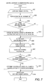
- FIG. 7 is a flowchart illustrating the control information generation processing carried out by the cache optimization unit according to the first embodiment of this invention.
- the cache optimization unit 110 starts loop processing for the data pinning control (Step S 201 ).
- the cache optimization unit 110 reads the I/O monitoring information (Step S 202 ).
- the number of pieces of the read I/O monitoring information depends on an analysis method, and the I/O monitoring information is read at a predetermined time interval such as every one hour. Moreover, the cache optimization unit 110 may obtain the application data subject to the access of an I/O request from the storage server 300 based on the read I/O monitoring information.
- the cache optimization unit 110 analyzes the read I/O monitoring information, and determines whether application data requiring the pinning exists or not (Step S 203 ). Specifically, the following processing is carried out.
- the cache optimization unit 110 refers to addresses included in the I/O requests included in the predetermined time interval, and counts the number of I/O requests for each of the addresses. In a case where the number of the I/O requests is equal to or more than a threshold, the cache optimization unit 110 determines that application data requiring the pinning exists. It should be noted that the threshold is set in advance.
- the cache optimization unit 110 analyzes a content of the application data read from the storage server 300 based on the I/O monitoring information, and, in a case where the application data corresponds to the important information such as management information in the service, determines that application data requiring the pinning exists.
- the cache optimization unit 110 proceeds to Step S 205 .
- the cache optimization unit 110 determines control contents, and registers the determined control contents to the control information 221 (Step S 204 ). Specifically, the following processing is carried out.
- the cache optimization unit 110 determines an address for making access to the application data requiring the pinning, and an application 230 that uses this application data based on the I/O monitoring information. Moreover, the cache optimization unit 110 determines the issuance cycle of the dummy I/O request. The issuance cycle of the dummy I/O request is calculated, for example, as described below.
- the cache optimization unit 110 calculates the issuance intervals of the I/O requests for reading the application data requiring the pinning based on the I/O monitoring information.
- the cache optimization unit 110 identifies the shortest issuance interval of the I/O request out of the calculated issuance intervals of the I/O requests.
- the cache optimization unit 110 determines one tenth of the identified shortest issuance cycle of the I/O request as the issuance interval of the dummy I/O request.
- a description has been given of the example of the calculation method for the issuance cycle of the dummy I/O request.
- the cache optimization unit 110 determines the ratio of the I/O band used when the dummy I/O request is issued.
- a ratio set in advance is used. It should be noted that in place of the ratio of the I/O band, a range of the ratio of the I/O band may be determined.
- the I/O request monitoring unit 220 can change the ratio of the I/O band to be used depending on an actually used state of the I/O band when the dummy I/O request is issued.
- the cache optimization unit 110 adds one entry to the control information 221 , sets the identifier of the application 230 that uses the application data requiring the pinning to the application ID 501 of the added entry, and sets “data pinning control” to the control type 502 .
- the cache optimization unit 110 sets the address for making access to the application data requiring the pinning to the monitoring address 503 of the added entry, and sets the address, the issuance cycle, and the ratio of the I/O band for making access to the application data requiring the pinning to the control policy 504 .
- the same address is set to the monitoring address 503 and the control policy 504 .
- the cache optimization unit 110 determines whether or not all the pieces of the I/O monitoring information stored in the memory 102 have been processed (Step S 205 ).
- the cache optimization unit 110 returns to Step S 202 , and carries out the same processing.
- the cache optimization unit 110 starts loop processing for the data read-ahead control (Step S 206 ).
- the cache optimization unit 110 reads the I/O monitoring information (Step S 207 ).
- the number of pieces of the read I/O monitoring information depends on an analysis method, and the I/O monitoring information is read in units of the application 230 .
- the cache optimization unit 110 may obtain the application data subject to the access of an I/O request from the storage server 300 based on the read I/O monitoring information.
- the cache optimization unit 110 analyzes the read I/O monitoring information, and determines whether service information requiring reading ahead exists or not (Step S 208 ). Specifically, the following processing is carried out.
- the cache optimization unit 110 identifies application data to be read by each of the applications 230 within a short period of time and in a large amount. For example, in a case where an I/O request for reading the same file is issued ten or more times within one minute, the cache optimization unit 110 identifies this file as application data to be read within a short period of time and in a large amount. In a case where application data to be read within a short period of time and in a large amount exists, the cache control algorithm determines that application data requiring reading ahead exists.
- the cache optimization unit 110 may recognize an execution sequence of the applications 230 , and may treat application data, which is read when an arbitrary application 230 finishes processing and another application 230 starts processing after this arbitrary application 230 , as data requiring the reading ahead.
- the cache optimization unit 110 proceeds to Step S 210 .
- the cache optimization unit 110 determines control contents, and registers the determined control contents to the control information 221 (Step S 209 ). Specifically, the following processing is carried out.
- the cache optimization unit 110 determines an address for making access to the application data requiring the reading ahead, and an application 230 that issues a dummy I/O request based on the I/O monitoring information.
- the cache optimization unit 110 determines the ratio of the I/O band used when the dummy I/O request is issued.
- a ratio set in advance is used. It should be noted that in place of the ratio of the I/O band, a range of the ratio of the I/O band may be determined.
- the I/O request monitoring unit 220 can change the ratio of the I/O band to be used depending on an actually used state of the I/O band when the dummy I/O request is issued.
- the cache optimization unit 110 determines a monitoring address triggering the issuance of the dummy I/O request.
- the monitoring address triggering the issuance of the dummy I/O request is determined as described below, for example.
- the cache optimization unit 110 identifies, based on the I/O monitoring information, an I/O request issued ten minutes before an I/O request for application data requiring the reading ahead is detected. The cache optimization unit 110 determines an address included in the identified I/O request as the monitoring address.
- the cache optimization unit 110 identifies an application 230 issuing an I/O request for making access to application data requiring the reading ahead based on the I/O monitoring information and the service management information.
- the cache optimization unit 110 identifies, based on the service management information, an application 230 carrying out processing before this application 230 .
- the cache optimization unit 110 identifies, based on the I/O monitoring information and the service management information, application data to which the identified application 230 makes access 10 minutes before the identified application 230 finishes the processing and determines the address of the application data as the monitoring address.
- the cache optimization unit 110 adds one entry to the control information 221 , sets the identifier of the application 230 that is determined to issue a dummy I/O request to the application ID 501 of the added entry, and sets “data read-ahead control” to the control type 502 .
- the cache optimization unit 110 sets the determined monitoring address to the monitoring address 503 of the added entry, and sets the address and the ratio of the I/O band for making access to the application data requiring the reading ahead to the control policy 504 .
- the cache optimization unit 110 determines whether or not all the pieces of the I/O monitoring information stored in the memory 102 have been processed (Step S 210 ).
- the cache optimization unit 110 returns to Step S 207 , and carries out the same processing.
- the cache optimization unit 110 finishes the control information generation processing.
- the loop processing for the read-ahead control may be carried out first. Moreover, after the control information generation processing is finished, the cache optimization unit 110 may delete the I/O monitoring information stored in the memory 102 .
- FIG. 8 is a flowchart illustrating the I/O request monitoring processing carried out by the I/O request monitoring unit 220 according to the first embodiment of this invention.
- the I/O request monitoring unit 220 starts the I/O monitoring processing described below when a service is started after the control information 221 is set.
- the I/O request monitoring unit 220 reads the control information 221 set by the cache optimization unit 110 , thereby starting the monitoring of the I/O request (Step S 301 ).
- the I/O request monitoring unit 220 traps the I/O request issued by the application 230 , thereby detecting the I/O request (Step S 302 ).
- the I/O request monitoring unit 220 refers to the control information 221 , thereby determining whether the detected I/O request is an I/O request including a monitoring address or not (Step S 303 ).
- the I/O request monitoring unit 220 refers to the control information 221 , thereby searching for an entry in which the identifier of the application that has issued the I/O request is stored in the application ID 501 , and an address included in the I/O request is stored in the monitoring address 503 . In a case where an entry matching the address included in the I/O request is retrieved, the I/O request monitoring unit 220 determines that the detected I/O request is an I/O request including the monitoring address.
- the I/O request monitoring unit 220 proceeds to Step S 308 .
- the I/O request monitoring unit 220 determines whether the control type 502 of the retrieved entry is “data read-ahead control” or not (Step S 304 ).
- the I/O request monitoring unit 220 issues a dummy I/O request based on the information set to this entry (Step S 305 ). Then, the I/O request monitoring unit 220 proceeds to Step S 308 .
- the I/O request monitoring unit 220 uses the I/O band stored in the control policy 504 , thereby issuing a dummy I/O request including an address stored in the control policy 504 .
- the I/O request monitoring unit 220 sets the identifier of a dummy application 230 as an issuance source of the dummy I/O request.
- the I/O request monitoring unit 220 can receive a response to the dummy I/O request.
- the I/O request monitoring unit 220 receives application data as a response to the dummy I/O request, and may discard this application data.
- the cache driver 213 determines whether or not application data exists in the server cache 240 . In a case where the application data does not exist in the server cache 240 , the cache driver 213 issues an I/O request for requesting the storage server 300 to read the application data. Moreover, the cache driver 213 stores the data read from the storage server 300 in the server cache 240 .
- the I/O request monitoring unit 220 starts the timer (Step S 306 ). On this occasion, the issuance cycle stored in the control policy 504 of the retrieved entry is set to the timer.
- the I/O request monitoring unit 220 In a case of being notified of an elapse of a period corresponding to the issuance cycle by the timer, the I/O request monitoring unit 220 periodically issues the dummy I/O request based on the information set in the retrieved entry (Step S 307 ). Then, the I/O request monitoring unit 220 proceeds to Step S 308 .
- the I/O request monitoring unit 220 uses the I/O band stored in the control policy 504 , thereby issuing a dummy I/O request including an address stored in the control policy 504 .
- the I/O request monitoring unit 220 sets the identifier of a dummy application as an issuance source of the dummy I/O request.
- the I/O request monitoring unit 220 can receive a response to the dummy I/O request.
- the I/O request monitoring unit 220 may discard the data read from the server cache 240 as a result of the dummy I/O request.
- the cache driver 213 determines whether or not application data exists in the server cache 240 . On this occasion, the application data exists in the server cache 240 , and the application data is thus read from the server cache 240 . The access to the application data requiring the pinning is periodically detected. Therefore, even when the cache driver 213 carries out the cache control, for example, based on the LRU control, the application data is not evicted from the server cache 240 .
- the I/O request monitoring unit 220 determines whether the service has been finished or not (Step S 308 ).
- the I/O request monitoring unit 220 returns to Step S 302 , and continues the monitoring of the I/O request. In a case where it is determined that the service has been finished, the I/O request monitoring unit 220 finishes the I/O request monitoring processing.
- the cache optimization unit 110 is included in the management server 100 and the I/O request monitoring unit 220 is included in the service server 200 , but this invention is not limited to this case.
- the service server 200 may include the cache optimization unit 110 .
- the arrangement of the application data stored in the server cache 240 can be optimized.
- the processing performance of the application 230 in the service server 200 can be improved.
- the dummy I/O request is issued based on the issuance cycle, but, in a modified example, the dummy I/O request is issued based on an access counter of the server cache 240 managed by the cache driver 213 .
- the access counter is information used to manage the number of accesses blocks of data in the server cache 240 .
- the computer system configuration, and the configurations of the management server 100 , the service server 200 , and the storage server 300 according to the modified example are the same as those of the first embodiment, and a description thereof is therefore omitted.
- the access analysis processing according to the modified example is the same as that of the first embodiment, and a description thereof is therefore omitted.
- information stored in the control policy 504 of an entry corresponding to the “data pinning control” in the control information 221 is different. Specifically, an issuance cycle is not set to the control policy 504 .
- Step S 204 the processing of determining the issuance cycle of the dummy I/O request is not carried out.
- the other pieces of processing are the same as those of the first embodiment.
- Step S 304 it is determined that the control type is “data pinning control”, the I/O request monitoring unit 220 obtains a value of the access counter from the cache driver 213 , and inquires of an arrangement (block) on the server cache 240 in which application data requiring the pinning is stored.
- the I/O request monitoring unit 220 calculates an average of the numbers of accesses to all the blocks based on the access counter. Further, the I/O request monitoring unit 220 determines whether the number of accesses to the block storing the application data requiring the pinning is more than the calculated average.
- Step S 308 the I/O request monitoring unit 220 proceeds to Step S 308 .
- the I/O request monitoring unit 220 issues a dummy I/O request (Step S 307 ).
- the information of programs, tables, and files to implement the functions may be stored in a storage device such as a memory, a hard disk drive, or an SSD (a Solid State Drive), or a storage medium such as an IC card, or an SD card.
- a storage device such as a memory, a hard disk drive, or an SSD (a Solid State Drive), or a storage medium such as an IC card, or an SD card.
Landscapes
- Engineering & Computer Science (AREA)
- Theoretical Computer Science (AREA)
- Physics & Mathematics (AREA)
- General Engineering & Computer Science (AREA)
- General Physics & Mathematics (AREA)
- Human Computer Interaction (AREA)
- Computer Networks & Wireless Communication (AREA)
- Signal Processing (AREA)
- Memory System Of A Hierarchy Structure (AREA)
- Information Retrieval, Db Structures And Fs Structures Therefor (AREA)
Applications Claiming Priority (2)
| Application Number | Priority Date | Filing Date | Title |
|---|---|---|---|
| JP2014-060117 | 2014-03-24 | ||
| JP2014060117A JP6199782B2 (ja) | 2014-03-24 | 2014-03-24 | 計算機システム |
Publications (2)
| Publication Number | Publication Date |
|---|---|
| US20150268858A1 US20150268858A1 (en) | 2015-09-24 |
| US9652155B2 true US9652155B2 (en) | 2017-05-16 |
Family
ID=54142134
Family Applications (1)
| Application Number | Title | Priority Date | Filing Date |
|---|---|---|---|
| US14/642,873 Active 2035-07-31 US9652155B2 (en) | 2014-03-24 | 2015-03-10 | Computer system, cash data management method, and computer |
Country Status (2)
| Country | Link |
|---|---|
| US (1) | US9652155B2 (enExample) |
| JP (1) | JP6199782B2 (enExample) |
Cited By (1)
| Publication number | Priority date | Publication date | Assignee | Title |
|---|---|---|---|---|
| US12015498B1 (en) * | 2018-11-09 | 2024-06-18 | Amazon Technologies, Inc. | Electronic device configuration using dummy devices |
Families Citing this family (3)
| Publication number | Priority date | Publication date | Assignee | Title |
|---|---|---|---|---|
| US10131042B2 (en) | 2013-10-21 | 2018-11-20 | Milwaukee Electric Tool Corporation | Adapter for power tool devices |
| WO2017183177A1 (ja) * | 2016-04-22 | 2017-10-26 | 株式会社日立製作所 | 計算機システム、キャッシュ制御方法、及び計算機 |
| JP7220997B2 (ja) * | 2018-05-31 | 2023-02-13 | アズビル株式会社 | 施設監視システム、および、施設監視システムにおける通信方法 |
Citations (7)
| Publication number | Priority date | Publication date | Assignee | Title |
|---|---|---|---|---|
| JP2000293317A (ja) | 1996-04-08 | 2000-10-20 | Hitachi Ltd | 記憶制御装置 |
| US20010029519A1 (en) * | 1999-12-03 | 2001-10-11 | Michael Hallinan | Resource allocation in data processing systems |
| US20050193167A1 (en) * | 2004-02-26 | 2005-09-01 | Yoshiaki Eguchi | Storage subsystem and performance tuning method |
| US20080028143A1 (en) * | 2006-07-27 | 2008-01-31 | Atsushi Murase | Management system for a virtualized storage environment |
| US20090024793A1 (en) | 2007-07-17 | 2009-01-22 | Fontenot Nathan D | Method and apparatus for managing data in a hybrid drive system |
| US20110107241A1 (en) * | 2008-04-24 | 2011-05-05 | Cameron Stewart Moore | System and method for tracking usage |
| US20120297156A1 (en) * | 2011-05-20 | 2012-11-22 | Hitachi, Ltd. | Storage system and controlling method of the same |
Family Cites Families (3)
| Publication number | Priority date | Publication date | Assignee | Title |
|---|---|---|---|---|
| JP3117003B2 (ja) * | 1997-07-03 | 2000-12-11 | 日本電気株式会社 | 広域分散ファイルシステム |
| JP4767127B2 (ja) * | 2006-08-10 | 2011-09-07 | 株式会社日立製作所 | ファイルサーバ、計算機システム及びファイルの先読み方法。 |
| JP4801761B2 (ja) * | 2009-08-12 | 2011-10-26 | 株式会社日立製作所 | データベース管理方法およびシステム並びにその処理プログラム |
-
2014
- 2014-03-24 JP JP2014060117A patent/JP6199782B2/ja not_active Expired - Fee Related
-
2015
- 2015-03-10 US US14/642,873 patent/US9652155B2/en active Active
Patent Citations (8)
| Publication number | Priority date | Publication date | Assignee | Title |
|---|---|---|---|---|
| JP2000293317A (ja) | 1996-04-08 | 2000-10-20 | Hitachi Ltd | 記憶制御装置 |
| US20020099908A1 (en) | 1996-04-08 | 2002-07-25 | Yasutomo Yamamoto | Apparatus and method for reallocating logical to physical disk devices using a storage controller, with access frequency and sequential access ratio calculations and display |
| US20010029519A1 (en) * | 1999-12-03 | 2001-10-11 | Michael Hallinan | Resource allocation in data processing systems |
| US20050193167A1 (en) * | 2004-02-26 | 2005-09-01 | Yoshiaki Eguchi | Storage subsystem and performance tuning method |
| US20080028143A1 (en) * | 2006-07-27 | 2008-01-31 | Atsushi Murase | Management system for a virtualized storage environment |
| US20090024793A1 (en) | 2007-07-17 | 2009-01-22 | Fontenot Nathan D | Method and apparatus for managing data in a hybrid drive system |
| US20110107241A1 (en) * | 2008-04-24 | 2011-05-05 | Cameron Stewart Moore | System and method for tracking usage |
| US20120297156A1 (en) * | 2011-05-20 | 2012-11-22 | Hitachi, Ltd. | Storage system and controlling method of the same |
Cited By (1)
| Publication number | Priority date | Publication date | Assignee | Title |
|---|---|---|---|---|
| US12015498B1 (en) * | 2018-11-09 | 2024-06-18 | Amazon Technologies, Inc. | Electronic device configuration using dummy devices |
Also Published As
| Publication number | Publication date |
|---|---|
| US20150268858A1 (en) | 2015-09-24 |
| JP2015184883A (ja) | 2015-10-22 |
| JP6199782B2 (ja) | 2017-09-20 |
Similar Documents
| Publication | Publication Date | Title |
|---|---|---|
| US10891054B2 (en) | Primary data storage system with quality of service | |
| US10853274B2 (en) | Primary data storage system with data tiering | |
| US20200019516A1 (en) | Primary Data Storage System with Staged Deduplication | |
| US10275351B2 (en) | Journal management | |
| US9582222B2 (en) | Pre-cache similarity-based delta compression for use in a data storage system | |
| US11360705B2 (en) | Method and device for queuing and executing operation commands on a hard disk | |
| CN103635887B (zh) | 缓存数据的方法和存储系统 | |
| US9591096B2 (en) | Computer system, cache control method, and server | |
| US10664193B2 (en) | Storage system for improved efficiency of parity generation and minimized processor load | |
| US9652155B2 (en) | Computer system, cash data management method, and computer | |
| US10747773B2 (en) | Database management system, computer, and database management method | |
| WO2017126003A1 (ja) | 複数種類のメモリデバイスを含む計算機システム及び方法 | |
| US11249666B2 (en) | Storage control apparatus | |
| JP6200100B2 (ja) | 計算機システム | |
| US20150142768A1 (en) | Stored device with searching engines | |
| US9304918B2 (en) | Computer system and cache control method |
Legal Events
| Date | Code | Title | Description |
|---|---|---|---|
| AS | Assignment |
Owner name: HITACHI, LTD., JAPAN Free format text: ASSIGNMENT OF ASSIGNORS INTEREST;ASSIGNORS:KONDO, NOBUKAZU;SUGIMOTO, KEN;SIGNING DATES FROM 20150217 TO 20150220;REEL/FRAME:035122/0965 |
|
| STCF | Information on status: patent grant |
Free format text: PATENTED CASE |
|
| MAFP | Maintenance fee payment |
Free format text: PAYMENT OF MAINTENANCE FEE, 4TH YEAR, LARGE ENTITY (ORIGINAL EVENT CODE: M1551); ENTITY STATUS OF PATENT OWNER: LARGE ENTITY Year of fee payment: 4 |
|
| AS | Assignment |
Owner name: HITACHI VANTARA, LTD., JAPAN Free format text: COMPANY SPLIT;ASSIGNOR:HITACHI, LTD.;REEL/FRAME:069518/0761 Effective date: 20240401 |
|
| MAFP | Maintenance fee payment |
Free format text: PAYMENT OF MAINTENANCE FEE, 8TH YEAR, LARGE ENTITY (ORIGINAL EVENT CODE: M1552); ENTITY STATUS OF PATENT OWNER: LARGE ENTITY Year of fee payment: 8 |