US9651936B2 - Machining method - Google Patents
Machining method Download PDFInfo
- Publication number
- US9651936B2 US9651936B2 US14/475,166 US201414475166A US9651936B2 US 9651936 B2 US9651936 B2 US 9651936B2 US 201414475166 A US201414475166 A US 201414475166A US 9651936 B2 US9651936 B2 US 9651936B2
- Authority
- US
- United States
- Prior art keywords
- speed
- spindle
- rotational speed
- rvf
- machining
- Prior art date
- Legal status (The legal status is an assumption and is not a legal conclusion. Google has not performed a legal analysis and makes no representation as to the accuracy of the status listed.)
- Expired - Fee Related, expires
Links
Images


Classifications
-
- G—PHYSICS
- G05—CONTROLLING; REGULATING
- G05B—CONTROL OR REGULATING SYSTEMS IN GENERAL; FUNCTIONAL ELEMENTS OF SUCH SYSTEMS; MONITORING OR TESTING ARRANGEMENTS FOR SUCH SYSTEMS OR ELEMENTS
- G05B19/00—Programme-control systems
- G05B19/02—Programme-control systems electric
- G05B19/18—Numerical control [NC], i.e. automatically operating machines, in particular machine tools, e.g. in a manufacturing environment, so as to execute positioning, movement or co-ordinated operations by means of programme data in numerical form
- G05B19/404—Numerical control [NC], i.e. automatically operating machines, in particular machine tools, e.g. in a manufacturing environment, so as to execute positioning, movement or co-ordinated operations by means of programme data in numerical form characterised by control arrangements for compensation, e.g. for backlash, overshoot, tool offset, tool wear, temperature, machine construction errors, load, inertia
-
- G—PHYSICS
- G05—CONTROLLING; REGULATING
- G05B—CONTROL OR REGULATING SYSTEMS IN GENERAL; FUNCTIONAL ELEMENTS OF SUCH SYSTEMS; MONITORING OR TESTING ARRANGEMENTS FOR SUCH SYSTEMS OR ELEMENTS
- G05B2219/00—Program-control systems
- G05B2219/30—Nc systems
- G05B2219/41—Servomotor, servo controller till figures
- G05B2219/41115—Compensation periodical disturbance, like chatter, non-circular workpiece
-
- G—PHYSICS
- G05—CONTROLLING; REGULATING
- G05B—CONTROL OR REGULATING SYSTEMS IN GENERAL; FUNCTIONAL ELEMENTS OF SUCH SYSTEMS; MONITORING OR TESTING ARRANGEMENTS FOR SUCH SYSTEMS OR ELEMENTS
- G05B2219/00—Program-control systems
- G05B2219/30—Nc systems
- G05B2219/41—Servomotor, servo controller till figures
- G05B2219/41256—Chattering control
Definitions
- the present disclosure relates to a machining method of machining a workpiece using a machine tool, wherein the rotational speed of a spindle of the machine tool is periodically varied.
- chatter vibration deteriorates machining accuracy (in particular, surface accuracy).
- chatter vibration is roughly classified into forced chatter vibration and self-excited chatter vibration, and it is considered that forced chatter vibration is caused by an action of an excessively large external force or by synchronization between the frequency of an external force and the resonant frequency of a vibrating system and, on the other hand, self-excited chatter vibration is caused by continuation of cutting in which periodic variation in cutting resistance and periodic variation in thickness of cut enhance each other through interaction therebetween (the so-called “regeneration effect”).
- chatter vibration As a method of suppressing self-excited chatter vibration included in chatter vibration, a technique of periodically varying the rotational speed of a spindle at a predetermined amplitude has been suggested. Furthermore, a technique has been suggested in which the variation amplitude and the variation period of the spindle rotational speed are parameterized and the parameterized variation amplitude and variation period are changed when chatter vibration occurs.
- R 120/( m (2 n ⁇ 1) N ), where R is the rotational-speed variation period [s], m is the number of cutting edges of a tool, n represents an integer, and N is the average rotational speed of the spindle [min-1].
- the spindle rotational speed is varied at predetermined variation amplitude and variation period so as to break the periodicities of the variation in cutting resistance and the variation in thickness of cut, and thereby, self-excited chatter vibration is suppressed. Therefore, taking into consideration only effective suppression of self-excited chatter vibration, self-excited chatter vibration is more suppressed when the variation amplitude of the spindle rotational speed is larger, and, to the contrary, self-excited chatter vibration is more suppressed when the variation period of the spindle rotational speed is shorter.
- the present disclosure has been achieved in view of the above-described circumstances, and an object thereof is to provide a machining method which enables obtaining a preferable machining accuracy while appropriately suppressing self-excited chatter vibration.
- the present disclosure relates to a machining method of, in a machine tool, machining a workpiece while periodically varying a rotational speed of a spindle of the machine tool, the machining method comprising:
- correlation data indicative of correlation between the speed variation rate RVA of the rotational speed of the spindle, the speed variation period ratio RVF of the rotational speed of the spindle, and vibration occurring on a tool during machining when a workpiece is machined while periodically varying the rotational speed of the spindle is obtained in advance.
- This correlation data can be obtained by a machining simulation based on CAE analysis or the like using three-dimensional models of the machine tool, workpiece, and tool used for machining, or can be obtained by, during actual machining using the machine tool, the workpiece and the tool, measuring displacement (vibration) of the tool by an optical displacement sensor, an accelerometer or the like.
- the values of the speed variation rate RVA and the speed variation period ratio RVF are set based on the obtained correlation data so that the vibration of the tool is within an allowable range and machining accuracy is within an allowable range, and then the vibration amplitude and the variation period of the rotational speed of the spindle are determined based on the set speed variation rate RVA and the set speed variation period ratio RVF. Then, the spindle is rotated so that the rotational speed thereof varies at the determined variation amplitude and the determined variation period with respect to the target rotational speed, thereby machining the workpiece.
- the values of the speed variation rate RVA and the speed variation period ratio RVF are set based on the correlation data indicative of the correlation between the speed variation rate RVA of the rotational speed of the spindle, the speed variation period ratio RVF of the rotational speed of the spindle, and vibration occurring on the tool during machining so that the vibration of the tool is within an allowable range and machining accuracy is within an allowable range, a preferable machining accuracy can be achieved while self-exited chatter vibration is appropriately suppressed.
- the values of the speed variation rate RVA and the speed variation period ratio RVF are set based on the correlation data indicative of the correlation between the speed variation rate RVA of the rotational speed of the spindle, the speed variation period ratio RVF of the rotational speed of the spindle, and the vibration occurring on the tool during machining so that the vibration of the tool is within an allowable range and machining accuracy is within an allowable range, a preferable machining accuracy is achieved while self-excited chatter vibration is appropriately suppressed.
- the speed variation rate RVA is set to its minimum value and the speed variation period ratio RVF is set to its maximum value within the allowable vibration range of the tool, a preferable machining accuracy is achieved while self-excited chatter vibration is stably suppressed. Furthermore, when both of the speed variation rate RVA and the speed variation period ratio RVF are set to their respective minimum values, a more preferable machining accuracy is achieved while self-excited chatter vibration is properly suppressed.
- FIG. 1 is an explanatory diagram showing a machining model for carrying out a machining method according to one embodiment of the present disclosure
- FIG. 2 is an explanatory diagram for explaining a variation amplitude and a variation period of a spindle rotational speed in the machining method of the embodiment
- FIG. 3 is a state diagram showing correlation between a speed variation rate RVA, a speed variation period ratio RVF, and displacement (vibration) of a tool;
- FIG. 4 is a state diagram showing the correlation between the speed variation rate RVA, the speed variation period ratio RVF, and the displacement (vibration) of the tool;
- FIG. 5 is an explanatory diagram showing the displacement of the tool that results when the speed variation period ratio RVF is changed with the speed variation rate RVA set to 0.1;
- FIG. 6 is an explanatory diagram showing a state of the displacement of the tool that results when the speed variation rate RVA and the speed variation period ratio RVF are set to 0.1 and 0.2, respectively;
- FIG. 7 is an explanatory diagram showing a state of the displacement of the tool that results when the speed variation rate RVA and the speed variation period ratio RVF are set to 0.1 and 0.4, respectively;
- FIG. 8 is an explanatory diagram showing a state of the displacement of the tool that results when the speed variation rate RVA and the speed variation period ratio RVF are set to 0.1 and 0.8, respectively;
- FIG. 9 is an explanatory diagram showing a spindle rotational speed
- FIG. 10 is an explanatory diagram showing acceleration (vibration) of the tool that results when the spindle is rotated at the rotational speed shown in FIG. 9 ;
- FIG. 11 is an explanatory diagram showing the frequency components of the acceleration (vibration) of the tool during the period variation duration shown in FIG. 9 ;
- FIG. 12 is an explanatory diagram showing the frequency components of the acceleration (vibration) of the tool during the constant speed duration shown in FIG. 9 ;
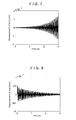
- FIG. 13 is an explanatory diagram showing a spindle rotational speed
- FIG. 14 is an explanatory diagram showing acceleration (vibration) of the tool that results when the spindle is rotated at the rotational speed shown in FIG. 13 ;
- FIG. 15 is an explanatory diagram showing the frequency components of the acceleration (vibration) of the tool during the period variation duration shown in FIG. 13 ;
- FIG. 16 is an explanatory diagram showing the frequency components of the acceleration (vibration) of the tool during the constant speed duration shown in FIG. 13 .
- FIG. 1 is an explanatory diagram showing the schematic model of the machine tool.
- the machine tool 1 of this embodiment includes a base 2 , a ball screw 4 supported by the base 2 to be rotatable, a feed motor 3 which rotates the ball screw 4 around its axis, a table 5 which is screwed to the ball screw 4 and is moved in the axial direction of the ball screw 4 (X-axis direction) by the rotation of the ball screw 4 , a spindle 6 disposed in an area above the table 5 , a spindle motor 7 which rotates the spindle 6 around its axis, a controller 10 which numerically controls the feed motor 3 and the spindle motor 7 , and a driver 11 which, based on a control signal transmitted from the controller 10 , supplies the motor 3 and the spindle motor 7 with power corresponding to the control signal.
- FIG. 1 depicts only a feed mechanism (the ball screw 4 and the feed motor 3 ) for moving the table 5 in the X-axis direction
- the machine tool 1 also includes a feed mechanism for moving the table 5 and the spindle 6 relative to each other in the Y-axis and Z-axis directions shown in FIG. 1 and operation of this feed mechanism is also controlled by the controller 10 and the driver 11 .
- the table 5 and the spindle 6 are moved relative to each other along the three orthogonal axes: the X axis, the Y axis, and the Z axis by the feed mechanisms including the feed motor 3 and the spindle motor 7 . Further, a workpiece W is placed on the table 5 and a tool 8 is attached to the spindle 6 , and the table 5 and the spindle 6 are moved relative to each other as appropriate in a state where the spindle 6 is rotated at a predetermined rotational speed, thereby machining the workpiece W.
- the machine tool used in the present disclosure is not limited to a machine tool having the above-described configuration and includes, besides an NC lathe, every type of known machine tool that cuts and machines a workpiece through relative rotation of a tool and the workpiece.
- a variation waveform of the rotational speed is not limited to a triangular waveform as shown in FIG. 2 , and may be a sinusoidal waveform or a trapezoidal waveform, for example.
- This correlation data can be obtained by a machining simulation based on CAE analysis or the like using three-dimensional models of the machine tool 1 , the workpiece W, and the tool 8 , or by measuring the vibration of the tool 8 by an accelerometer, an optical displacement sensor, or the like during actual machining using the machine tool 1 , the workpiece W, and the tool 8 . It is noted that cutting conditions for the machining simulation and the actual machining are cutting conditions which are to be actually applied and under which self-excited chatter vibration occurs.
- FIG. 3 shows a state diagram whose horizontal axis represents the speed variation rate RVA and whose vertical axis represents the speed variation period ratio RVF and which shows the magnitude (level) of displacement (vibration) of the tool 8 which is color-coded according to the magnitude of displacement and further is represented in gray scale.
- FIG. 4 is a state diagram whose vertical axis represents the displacement of the tool 8 and whose horizontal axes represent the speed variation rate RVA and the speed variation period ratio RVF and which shows the magnitude of displacement of the tool 8 which is color-coded according to the magnitude of displacement and represented in a three-dimensional manner and further is represented in gray scale.
- red becomes deeper as the displacement becomes larger
- blue becomes deeper as the displacement becomes smaller
- the middle is yellow.
- the feed rate Vs of the tool 8 is set to 2 ⁇ 10 ⁇ 3 [m/s], the width of cut a to 5 ⁇ 10 ⁇ 3 [m], the intrinsic cutting force Kt to 300 [MPa], the dynamic mass M to 10 [Ns 2 /m], the mechanical impedance B to 200 [Ns/m], and the dynamic rigidity K to 5 ⁇ 10 5 [N/m].
- the average rotational speed of the spindle 6 is set to 262 [rad/s], at which self-excited chatter vibration occurs, and the speed variation rate RVA and the speed variation period ratio RVF are each changed in a range of 0.001 or more to 1.0 or less.
- FIGS. 3 and 4 demonstrate that the displacement, i.e., vibration of the tool 8 is reduced as the speed variation rate RVA and the speed variation period ratio RVF each increase. Further, the results also demonstrate that sharp suppression of self-excited chatter vibration of the tool 8 starts near a point at which the speed variation rate RVA reaches 0.05 and the displacement of the tool 8 is well suppressed in an area in which the speed variation rate RVA is smaller than 0.05.
- FIG. 5 depicts the displacement of the tool 8 that results when the speed variation period ratio RVF is changed with the speed variation rate RVA fixed to 0.1. It is found that, in this case, setting the speed variation period ratio RVF to a value equal to or larger than 0.5 suppresses self-excited chatter vibration of the tool 8 .
- FIG. 6 depicts a state of the displacement of the tool 8 that results when the speed variation period ratio RVF is set to 0.2 with the speed variation rate RVA set to 0.1
- FIG. 7 depicts a state of the displacement of the tool 8 that results when the speed variation period ratio RVF is set to 0.4 with the speed variation rate RVA set to 0.1
- FIG. 8 depicts a state of the displacement of the tool 8 that results when the speed variation period ratio RVF is set to 0.8 with the speed variation rate RVA set to 0.1.
- self-excited chatter vibration of the tool 8 can be more stably suppressed as each of the speed variation rate RVA and the speed variation period ratio RVF is increased.
- the speed variation rate RVA and the speed variation period ratio RVF are set so that the vibration of the tool 8 is within an allowable range and machining accuracy is within an allowable range.
- the speed variation rate RVA is equal to or larger than 0.3 and the speed variation period ratio RVF is equal to or larger than 0.01
- the speed variation rate RVA be equal to or larger than 0.3 and the speed variation period ratio RVF be equal to or larger than 0.01.
- increasing the speed variation rate RVA means increasing the variation amplitude of the spindle rotational speed, and increasing the variation amplitude of the spindle rotational speed, for example, causes a great variation in the feed amount of tool per revolution of workpiece in the case of a lathe and similarly causes a great variation in the feed amount per revolution of tool in the case of a machining center.
- the surface roughness of a machined workpiece surface tends to become non-uniform, that is, machining accuracy tends to be deteriorated. Therefore, when the aspect of machining accuracy is taken into consideration, it is preferable that the speed variation rate RVA is as small as possible.
- increasing the speed variation period ratio RVF means reducing the variation period of the spindle rotational speed, and reducing the variation period of the spindle rotational speed, that is, varying the spindle rotational speed at a short period makes the surface roughness of a machined workpiece surface non-uniform and, also in this case, machining accuracy tends to be deteriorated.
- the degree of the effect on machining accuracy is smaller than that in the case of increasing the variation amplitude of the spindle rotational speed.
- the speed variation rate RVA is set to its minimum value and the speed variation period ratio RVF is set to its maximum value within the allowable vibration range of the tool 8 .
- the speed variation rate RVA is set to 0.3 and the speed variation period ratio RVF is set to 1.0.
- the speed variation rate RVA is set to its minimum value and the speed variation period ratio RVF is set to its maximum value within the allowable vibration range of the tool 8 , a preferable machining accuracy can be achieved while self-excited chatter vibration is stably suppressed.
- both of the speed variation rate RVA and the speed variation period ratio RVF may be set to their respective minimum values within the allowable vibration range of the tool 8 . In this case, a more preferable machining accuracy can be achieved while self-exited chatter vibration is properly suppressed.
- FIG. 10 depicts the result of detection of the vibration of the tool 8 using an acceleration sensor when the workpiece W is machined under the above-mentioned cutting conditions while rotating the spindle 6 at the rotational speed shown in FIG. 9 .
- the rotational speed of the spindle 6 shown in FIG. 9 is periodically varied at the speed variation rate RVA of 0.3 and the speed variation period ratio RVF of 0.01 with the average rotational speed N 0 set to 262 [rad/s] for about 6 [s] after the start of cutting and then is fixed to a constant rotational speed.
- ⁇ denotes the actual rotational speed of the spindle 6
- ⁇ ref denotes an input value input to the spindle motor 7 .
- FIGS. 11 and 12 depict the result of the spectral analysis.
- FIG. 11 depicts the frequency components of the acceleration (vibration) of the tool 8 during the period in which the rotational speed is periodically varied
- FIG. 12 depicts the frequency components of the acceleration (vibration) of the tool 8 during the period in which the rotational speed is fixed to the constant speed.
- self-excited chatter vibration of the tool 8 can be suppressed by periodically varying the rotational speed of the spindle 6 so that the speed variation rate RVA is 0.3 and the speed variation period ratio RVF is 0.01.
- FIG. 14 depicts the result of detection of the vibration of the tool 8 using an acceleration sensor when the workpiece W is machined under the above-mentioned cutting conditions while rotating the spindle 6 at the rotational speed shown in FIG. 13 .
- the rotational speed of the spindle 6 shown in FIG. 13 is periodically varied at the speed variation rate RVA of 0.4 and the speed variation period ratio RVF of 0.02 with the average rotational speed N 0 set to 262 [rad/s] for about 5 [s] after the start of cutting, and then is fixed to a constant rotational speed.
- ⁇ denotes the actual rotational speed of the spindle 6
- ⁇ ref denotes an input value input to the spindle motor 7 .
- the speed variation rate RVA is set to its minimum value and the speed variation period ratio RVF is set to its maximum value, or both of the speed variation rate RVA and the speed variation period ratio RVF are set to their respective minimum values
- the present disclosure is not limited thereto, and each of the speed variation rate RVA and the speed variation period ratio RVF may take any value as long as the vibration of the tool is within an allowable range and machining accuracy is within an allowable range.
Landscapes
- Engineering & Computer Science (AREA)
- Human Computer Interaction (AREA)
- Manufacturing & Machinery (AREA)
- Physics & Mathematics (AREA)
- General Physics & Mathematics (AREA)
- Automation & Control Theory (AREA)
- Automatic Control Of Machine Tools (AREA)
- Numerical Control (AREA)
Abstract
Description
R=120/(m(2n−1)N),
where R is the rotational-speed variation period [s], m is the number of cutting edges of a tool, n represents an integer, and N is the average rotational speed of the spindle [min-1].
-
- obtaining in advance correlation data indicative of correlation between a speed variation rate RVA of the rotational speed of the spindle, a speed variation period ratio RVF of the rotational speed of the spindle, and vibration occurring on a tool during machining when the workpiece is machined while periodically varying the rotational speed of the spindle;
- setting values of the speed variation rate RVA and the speed variation period ratio RVF on the basis of the obtained correlation data so that the vibration of the tool is within an allowable range and machining accuracy is within an allowable range, and then determining a variation amplitude and a variation period of the rotational speed of the spindle on the basis of the set speed variation rate RVA and the set speed variation period ratio RVF; and
- rotating the spindle so that the rotational speed of the spindle varies at the determined variation amplitude and the determined variation period with respect to a target rotational speed, thereby machining the workpiece,
- wherein
RVA=N A /N 0,
and
RVF=2τ/(N 0 ×T), - where T is the variation period [s] of the rotational speed of the spindle, NA is the variation amplitude [rad/s] of the rotational speed of the spindle, and N0 is the target rotational speed, that is, an average [rad/s] of the rotational speed of the spindle in a section T.
RVA=N A /N 0
RVF=2τ/(N 0 ×T)
N A =N 0 ×RVA,
and
T=2τ/(N 0 ×RVF).
N A =N 0 ×RVA=262×0.3=78.6 [rad/s],
and
T=2τ/(N 0 ×RVF)=2τ/(262×1.0)=0.024 [s].
Claims (9)
RVA=N A /N 0,
and
RVF=2τ/(N 0 ×T),
Applications Claiming Priority (2)
| Application Number | Priority Date | Filing Date | Title |
|---|---|---|---|
| JP2013-255798 | 2013-12-11 | ||
| JP2013255798A JP6139392B2 (en) | 2013-12-11 | 2013-12-11 | Processing method |
Publications (2)
| Publication Number | Publication Date |
|---|---|
| US20150160643A1 US20150160643A1 (en) | 2015-06-11 |
| US9651936B2 true US9651936B2 (en) | 2017-05-16 |
Family
ID=53271090
Family Applications (1)
| Application Number | Title | Priority Date | Filing Date |
|---|---|---|---|
| US14/475,166 Expired - Fee Related US9651936B2 (en) | 2013-12-11 | 2014-09-02 | Machining method |
Country Status (2)
| Country | Link |
|---|---|
| US (1) | US9651936B2 (en) |
| JP (1) | JP6139392B2 (en) |
Cited By (1)
| Publication number | Priority date | Publication date | Assignee | Title |
|---|---|---|---|---|
| US20160256977A1 (en) * | 2015-03-06 | 2016-09-08 | The University Of Tokyo | Machine Tool and Workpiece Machining Method |
Families Citing this family (8)
| Publication number | Priority date | Publication date | Assignee | Title |
|---|---|---|---|---|
| US9682455B2 (en) * | 2014-10-28 | 2017-06-20 | Dmg Mori Seiki Co., Ltd. | Chatter application interface |
| US10022832B2 (en) | 2015-03-31 | 2018-07-17 | Dmg Mori Seiki Co., Ltd. | Fine-tuning speed application interface |
| JP6915782B2 (en) | 2018-02-06 | 2021-08-04 | 国立大学法人東海国立大学機構 | Processing equipment and cutting method |
| JP7412695B2 (en) * | 2019-10-03 | 2024-01-15 | 慶應義塾 | Machine tools, numerical control devices and vibration suppression methods |
| JP7403282B2 (en) * | 2019-11-01 | 2023-12-22 | オークマ株式会社 | Monitoring device and method for spindle rotation speed in machine tools, machine tools |
| DE112022000659T5 (en) * | 2021-03-18 | 2023-10-26 | Fanuc Corporation | MACHINE TOOL CONTROL |
| WO2024185057A1 (en) * | 2023-03-08 | 2024-09-12 | ファナック株式会社 | Numerical control device and computer-readable storage medium |
| JP7573790B1 (en) * | 2024-02-02 | 2024-10-25 | 三菱電機株式会社 | Numerical control device, numerical control method, and numerical control program |
Citations (7)
| Publication number | Priority date | Publication date | Assignee | Title |
|---|---|---|---|---|
| JPS49105277A (en) | 1973-02-08 | 1974-10-04 | ||
| JP2000126991A (en) | 1998-10-24 | 2000-05-09 | Hitachi Seiki Co Ltd | Control device for NC machine tool |
| US20070088456A1 (en) * | 2005-04-07 | 2007-04-19 | University Of Florida Research Foundation, Inc. | System and method for tool point prediction using multi-component receptance coupling substructure analysis |
| US20100104388A1 (en) * | 2008-10-28 | 2010-04-29 | Okuma Corporation | Vibration suppressing method and vibration suppressing device for machine tool |
| US20120097411A1 (en) * | 2010-10-20 | 2012-04-26 | Okuma Corporation | Method for monitoring rotary shaft rotation speed fluctuation in machine tool, monitor apparatus, and machine tool |
| JP2012091283A (en) | 2010-10-27 | 2012-05-17 | Okuma Corp | Machine tool |
| US20130073251A1 (en) * | 2011-09-20 | 2013-03-21 | Okuma Corporation | Monitoring method and monitor apparatus for monitoring rotation speed of rotary shaft in machine tool, and machine tool |
Family Cites Families (3)
| Publication number | Priority date | Publication date | Assignee | Title |
|---|---|---|---|---|
| JP5674449B2 (en) * | 2010-12-21 | 2015-02-25 | オークマ株式会社 | Machine Tools |
| JP5507410B2 (en) * | 2010-10-20 | 2014-05-28 | オークマ株式会社 | Method and apparatus for monitoring spindle rotational speed in machine tool, machine tool |
| JP5631758B2 (en) * | 2011-01-19 | 2014-11-26 | オークマ株式会社 | Vibration suppression device |
-
2013
- 2013-12-11 JP JP2013255798A patent/JP6139392B2/en active Active
-
2014
- 2014-09-02 US US14/475,166 patent/US9651936B2/en not_active Expired - Fee Related
Patent Citations (7)
| Publication number | Priority date | Publication date | Assignee | Title |
|---|---|---|---|---|
| JPS49105277A (en) | 1973-02-08 | 1974-10-04 | ||
| JP2000126991A (en) | 1998-10-24 | 2000-05-09 | Hitachi Seiki Co Ltd | Control device for NC machine tool |
| US20070088456A1 (en) * | 2005-04-07 | 2007-04-19 | University Of Florida Research Foundation, Inc. | System and method for tool point prediction using multi-component receptance coupling substructure analysis |
| US20100104388A1 (en) * | 2008-10-28 | 2010-04-29 | Okuma Corporation | Vibration suppressing method and vibration suppressing device for machine tool |
| US20120097411A1 (en) * | 2010-10-20 | 2012-04-26 | Okuma Corporation | Method for monitoring rotary shaft rotation speed fluctuation in machine tool, monitor apparatus, and machine tool |
| JP2012091283A (en) | 2010-10-27 | 2012-05-17 | Okuma Corp | Machine tool |
| US20130073251A1 (en) * | 2011-09-20 | 2013-03-21 | Okuma Corporation | Monitoring method and monitor apparatus for monitoring rotation speed of rotary shaft in machine tool, and machine tool |
Non-Patent Citations (1)
| Title |
|---|
| Teruaki Ishibashi, Hiroshi Fujimoto, Shinji Ishii, Koji Yamamoto and Yuki Terada; "High Frequency Variation Speed Control of Spindle Motor for Self-Excited Chatter Vibration Suppression in NC Machine Tools"; The Papers of Technical Meeting on "Mechatronics Control"; The Institute of Electrical Engineers of Japan; Sep. 3, 2013; Lecture No. MEC-13-159. |
Cited By (2)
| Publication number | Priority date | Publication date | Assignee | Title |
|---|---|---|---|---|
| US20160256977A1 (en) * | 2015-03-06 | 2016-09-08 | The University Of Tokyo | Machine Tool and Workpiece Machining Method |
| US10137555B2 (en) * | 2015-03-06 | 2018-11-27 | The University Of Tokyo | Workpiece machining method |
Also Published As
| Publication number | Publication date |
|---|---|
| US20150160643A1 (en) | 2015-06-11 |
| JP2015112676A (en) | 2015-06-22 |
| JP6139392B2 (en) | 2017-05-31 |
Similar Documents
| Publication | Publication Date | Title |
|---|---|---|
| US9651936B2 (en) | Machining method | |
| US9846428B2 (en) | Controller for spindle motor | |
| US9138848B2 (en) | Method and apparatus for suppressing vibration | |
| CN101310921B (en) | Machine tool vibration suppressing device and vibration suppressing method | |
| CN111052015B (en) | Numerical control system and motor control device | |
| JP6625794B2 (en) | A method for calculating a spindle stable rotational speed capable of suppressing chatter vibration, a method for notifying the method, a method for controlling a spindle rotational speed, an NC program editing method, and an apparatus therefor. | |
| JP6578195B2 (en) | Method for deriving natural frequency of cutting tool, method for creating stability limit curve, and device for deriving natural frequency of cutting tool | |
| US9211624B2 (en) | Vibration determination method and vibration determination device | |
| EP2669755A1 (en) | Machining error computation device, machining error computation method, machining control device and machining control method | |
| US9612595B2 (en) | Chatter vibration suppressing method and machine tool | |
| Ismail et al. | Chatter suppression in five-axis machining of flexible parts | |
| JP4433422B2 (en) | Vibration suppression device | |
| EP2660671A1 (en) | Processing control apparatus, and processing control method | |
| JP6311635B2 (en) | Numerical control device and control method | |
| JP5507410B2 (en) | Method and apparatus for monitoring spindle rotational speed in machine tool, machine tool | |
| JP7101883B2 (en) | Numerical control device | |
| JP2012196741A (en) | Rotational speed display device | |
| JP6521526B2 (en) | Motor drive control device and machine tool provided with the same | |
| CN112743392B (en) | Device and method for monitoring spindle rotation speed in machine tool, and machine tool | |
| JP5734131B2 (en) | Rotational speed display device | |
| KR102128553B1 (en) | Method of controlling vibrations in machine tool | |
| JP5226484B2 (en) | Chatter vibration suppression method | |
| JP5631792B2 (en) | Machine tool monitoring device | |
| JP2016043443A (en) | Rotational speed display method | |
| JP6490520B2 (en) | Motor drive control device and machine tool equipped with the same |
Legal Events
| Date | Code | Title | Description |
|---|---|---|---|
| AS | Assignment |
Owner name: THE UNIVERSITY OF TOKYO, JAPAN Free format text: ASSIGNMENT OF ASSIGNORS INTEREST;ASSIGNORS:FUJIMOTO, HIROSHI;ISHIBASHI, TERUAKI;ISHII, SHINJI;AND OTHERS;SIGNING DATES FROM 20140730 TO 20140826;REEL/FRAME:033653/0301 Owner name: DMG MORI SEIKI CO., LTD., JAPAN Free format text: ASSIGNMENT OF ASSIGNORS INTEREST;ASSIGNORS:FUJIMOTO, HIROSHI;ISHIBASHI, TERUAKI;ISHII, SHINJI;AND OTHERS;SIGNING DATES FROM 20140730 TO 20140826;REEL/FRAME:033653/0301 |
|
| AS | Assignment |
Owner name: DMG MORI SEIKI CO., LTD., JAPAN Free format text: ASSIGNMENT OF ASSIGNORS INTEREST;ASSIGNORS:FUJIMOTO, HIROSHI;ISHIBASHI, TERUAKI;ISHII, SHINJI;AND OTHERS;SIGNING DATES FROM 20140730 TO 20140831;REEL/FRAME:033988/0762 Owner name: THE UNIVERSITY OF TOKYO, JAPAN Free format text: ASSIGNMENT OF ASSIGNORS INTEREST;ASSIGNORS:FUJIMOTO, HIROSHI;ISHIBASHI, TERUAKI;ISHII, SHINJI;AND OTHERS;SIGNING DATES FROM 20140730 TO 20140831;REEL/FRAME:033988/0762 |
|
| STCF | Information on status: patent grant |
Free format text: PATENTED CASE |
|
| CC | Certificate of correction | ||
| FEPP | Fee payment procedure |
Free format text: MAINTENANCE FEE REMINDER MAILED (ORIGINAL EVENT CODE: REM.); ENTITY STATUS OF PATENT OWNER: LARGE ENTITY |
|
| LAPS | Lapse for failure to pay maintenance fees |
Free format text: PATENT EXPIRED FOR FAILURE TO PAY MAINTENANCE FEES (ORIGINAL EVENT CODE: EXP.); ENTITY STATUS OF PATENT OWNER: LARGE ENTITY |
|
| STCH | Information on status: patent discontinuation |
Free format text: PATENT EXPIRED DUE TO NONPAYMENT OF MAINTENANCE FEES UNDER 37 CFR 1.362 |
|
| FP | Lapsed due to failure to pay maintenance fee |
Effective date: 20210516 |