US965166A - Electric friction-clutch. - Google Patents
Electric friction-clutch. Download PDFInfo
- Publication number
- US965166A US965166A US53203209A US1909532032A US965166A US 965166 A US965166 A US 965166A US 53203209 A US53203209 A US 53203209A US 1909532032 A US1909532032 A US 1909532032A US 965166 A US965166 A US 965166A
- Authority
- US
- United States
- Prior art keywords
- clutch
- tapering
- armature
- electric friction
- shaft
- Prior art date
- Legal status (The legal status is an assumption and is not a legal conclusion. Google has not performed a legal analysis and makes no representation as to the accuracy of the status listed.)
- Expired - Lifetime
Links
- 241000239290 Araneae Species 0.000 description 1
- RTAQQCXQSZGOHL-UHFFFAOYSA-N Titanium Chemical compound [Ti] RTAQQCXQSZGOHL-UHFFFAOYSA-N 0.000 description 1
- 238000005266 casting Methods 0.000 description 1
- 238000003384 imaging method Methods 0.000 description 1
Images

Classifications
-
- F—MECHANICAL ENGINEERING; LIGHTING; HEATING; WEAPONS; BLASTING
- F16—ENGINEERING ELEMENTS AND UNITS; GENERAL MEASURES FOR PRODUCING AND MAINTAINING EFFECTIVE FUNCTIONING OF MACHINES OR INSTALLATIONS; THERMAL INSULATION IN GENERAL
- F16D—COUPLINGS FOR TRANSMITTING ROTATION; CLUTCHES; BRAKES
- F16D27/00—Magnetically- or electrically- actuated clutches; Control or electric circuits therefor
- F16D27/02—Magnetically- or electrically- actuated clutches; Control or electric circuits therefor with electromagnets incorporated in the clutch, i.e. with collecting rings
- F16D27/04—Magnetically- or electrically- actuated clutches; Control or electric circuits therefor with electromagnets incorporated in the clutch, i.e. with collecting rings with axially-movable friction surfaces
- F16D27/06—Magnetically- or electrically- actuated clutches; Control or electric circuits therefor with electromagnets incorporated in the clutch, i.e. with collecting rings with axially-movable friction surfaces with friction surfaces arranged within the flux
Definitions
- My invention relates to various new aml useful improvements in electric friction clutches, which are particularly applicable to motorcycles or automobile vehicles.
- the ob ect l have in riew is the produ tion of a friction clutch which will be more certain in its operation titan those heretofore constructed. and which will be compa t.
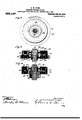
- FIG. 4 a cross section of one of the lutches shown at the left of Fig. 1, illustrating the details thereof.
- supporting shaft 9 is provided with a ilurality of gears 10. ll. l2. and lil thereon. uterpmed between the gears It), ll, 12, 13 am] H. and the shaft 9. are electric clutches l5, l6, l7. l8 and l! res wctively, which are i adapted to be successively operated.
- the friction clutch illustrated in the drawings comprises essentially a magnetic member 20. and an armature member 21.
- the former being preferably keyed directly to the shaft 9. and the latter -la-iug carried by the, sereral gears which are capable of
- the magnetic member 20 of each electric friction clutch comprises preferably a trough .-haped circular casting. having tapered pole lll' 'tfi or rims 21. 23', the coil 26 being seated a-twecu said pole pieces as shown.
- the armature member 21 is provided with pockcts :27, .57, with which the p le pieces of the magnetic member are adapted to enga as, said arnniture member being also provi ed with a large over-Imaging rim .58 with which the outer face of the magnetic member may engage to form an increased frictional surface as will be understood.
- each clutch is preferably keyed to a suitable spider 29, which in turn is keyed to the shaft 9, so as to hold the ma netic member of each clutch rigidly in position.
- the armature member of each clutch is adapted to be moved toward and away from the magnetic member. the. several gears being for this purpose loosely mounted upon the slut ft l whereby the necessity of employing sliding keys is done away with.
- the two members of each clutch are preferably normally separated by means of a spring 80 but if desired the said springs as dispensed with. 4
- each coil .26 is elfected by insulated wires embedded in a slot tll, out. in the shaft 9 and leadin to insulated contact rings 32, me of sai rings beingtheret'ore used for each clutch.
- the return or ground ctmuection from each-coil may be carried directly to the shaft-9, through the I being suitably grouielcd, such as through a bru-h 43 ee Fig. Iii engaging a collecting ring il on the shaft 9.
- eieetrii l'rit'tion cluteh.
- mnnprising Ill mmhination a trough-shaped tnagm-liv memher tuning an energized t'tlil therein and provided nith two tapering pole llit'v'ror rims.
Landscapes
- Engineering & Computer Science (AREA)
- General Engineering & Computer Science (AREA)
- Physics & Mathematics (AREA)
- Electromagnetism (AREA)
- Mechanical Engineering (AREA)
- Mechanical Operated Clutches (AREA)
Description
L. H. DYE!- BIMIIO B10110! 01.0108. Anuunol run as". a. an. an": no. a. 1m.
965,166, mum July 26, 1910.
I llIl'll-IIII 1.
m?) eoaaa. "insular a 1 Lennard Haul. mnmlyrr 0 4 v v v 0- L. H. DYBR. 21.201310 "10110! CLUTCH- nrucnxu nun n". 2:. m1. nun
DIG. I. 1.0.-
Patentod July 26, 1910.
' llIlll'h-IIIIT I.
[new/z (0/ W1! en 0. 1:
UNITED sTA r cs rENfr OFFICE.
TiEONARD HUNTRESS DYER. OI GREENWIC'H. CONNECTICUT. ASSXGNOR OF ONE-FOURTH TO FRANK L. DYER. OF MCNTCLAIR. NEW J ERSEY.
ELECTIHC FRICTION CLUTCH.
Specification of Letters Patent.
I'atenteil July 26. 1910.
Application filed September 22. 1887, Serial No. 652.532 Rene red December 8. 1909. Serial No. 532,032.
To all whom it may concern: I
Be it known that l. Liroxaao llt's'rmzss Dyna. a citizen of the United filttltm re-.iding in Greenwich. in the county of Fairtiehl. State of Connecticut, have invented certain new and useful Improveumits in Electric Friction-Clutches: and 1 do hereby declare the following to be a full. clear, and exact description of the invention, which will en able others skilled in the art to which it appertains to make and use the same.
My invention relates to various new aml useful improvements in electric friction clutches, which are particularly applicable to motorcycles or automobile vehicles.
The ob ect l have in riew is the produ tion of a friction clutch which will be more certain in its operation titan those heretofore constructed. and which will be compa t.
.Qthcr objects will more fully appear from the following specification aml aecompanying drawings.
in order that, my invention may be better understood, attention is directed to the am eompauying drawings forming a part of this spm-ilication. and in which Figure l is an enlarged sect ion illu.-t rating one form of electric clutch; Fig. 1. a face view of the clutch and gear wheel shown at the right of Fig. l. illustrating the details thereof; Fig. 3, a cross section of Fig. 2:
Fig. 4, a cross section of one of the lutches shown at the left of Fig. 1, illustrating the details thereof.
in all of the above \ien's correspomling parts are re weseuted by the same numerals. supporting shaft 9 is provided with a ilurality of gears 10. ll. l2. and lil thereon. uterpmed between the gears It), ll, 12, 13 am] H. and the shaft 9. are electric clutches l5, l6, l7. l8 and l!) res wctively, which are i adapted to be successively operated.
The friction clutch illust rated in the drawings comprises essentially a magnetic member 20. and an armature member 21. the former being preferably keyed directly to the shaft 9. and the latter -la-iug carried by the, sereral gears which are capable of |ongitudinal movement on said shaft. thereby tiniug away with the "necessity of key for the sliding members. in the t'nse of the gear lit, which is larger than the clutch. it is poible to carry the armature member directly upon one face of said gear as hown in Fig.
25, the said armature member being secured in place by bolts .32. but with the other gears which are smaller than the clutch. it is desllnl lt' to carry the armature member upon the sleet-t- '13. ast integral with each gear as shown in Fig. 4. i
The magnetic member 20 of each electric friction clutch comprises preferably a trough .-haped circular casting. having tapered pole lll' 'tfi or rims 21. 23', the coil 26 being seated a-twecu said pole pieces as shown. The armature member 21 is provided with pockcts :27, .57, with which the p le pieces of the magnetic member are adapted to enga as, said arnniture member being also provi ed with a large over-Imaging rim .58 with which the outer face of the magnetic member may engage to form an increased frictional surface as will be understood. The magnetic member of each clutch is preferably keyed to a suitable spider 29, which in turn is keyed to the shaft 9, so as to hold the ma netic member of each clutch rigidly in position. The armature member of each clutch, however, is adapted to be moved toward and away from the magnetic member. the. several gears being for this purpose loosely mounted upon the slut ft l whereby the necessity of employing sliding keys is done away with. The two members of each clutch are preferably normally separated by means of a spring 80 but if desired the said springs as dispensed with. 4
The connections to each coil .26 is elfected by insulated wires embedded in a slot tll, out. in the shaft 9 and leadin to insulated contact rings 32, me of sai rings beingtheret'ore used for each clutch. The return or ground ctmuection from each-coil may be carried directly to the shaft-9, through the I being suitably grouielcd, such as through a bru-h 43 ee Fig. Iii engaging a collecting ring il on the shaft 9.
ln ai-cordance with the provisions of the patent statutes, l haw described the principle of my invention, together with the aparatus which i now consider to represent the lat-l 'Htlunllltll'lli thereof. hat I tlt'fii pit-em or riot.
and a loo-e euiiperating armature mem er having tapering mel eta.aml an met-hanging tapermg flange. Substantiall as set f rth.
therein and provided with two tapering pule a tom's H Ti H I :I l l I i it w iii] N't'u t i l i ,1! :I HI "I t it tt' lln'lula-r hm ing pin-hob aml an overhanging linnge. .-nh-'tanti:tll t' as .-et forth.
2.. .\li impruu'tl t'ltft'il'l fl'i 'ti ll t'llttt'll. anprirdng in vomhinatinn n list-d troughdmped magm-titnn-mlwr. having an energizwl mil t'la-rein and prm'lded with tan tapering pole l il'ivh' or rims. and a lmmeooperating armature inelnla'r lnn'lng [an-ltets, ana an met-hanging ll:tllgt:,\-tlln.-ttlllttnliy 2. $01 l'orth.
.\n improved eieetrii: l'rit'tion cluteh. mnnprising Ill mmhination a trough-shaped tnagm-liv memher tuning an energized t'tlil therein and provided nith two tapering pole llit'v'ror rims. nml n roi perating armature nn-tnher hating an mljmtahle part carrying pm'kets. and an overhanging flange, anhr-tuntinlly as set forth.
-I. An improved eleetrie frivtie-a elnteh eomprising in eomhination, a trough-shaped umg'm'llt? memher having an energized eoil therein and provided with two tapering polo 5. .\n improved electrie frietion clutch PulHptiHittg in eomhination. a trongh-slmlml magnetie member having an energized eoil therein and provided with two tapering pole pitt'es or rims. and a looneoii wrative armatnre memher haviw' an adjlmtahle part earrying tapering pmeliets. am an overhanging tapering flange. snlmtantially as set forth.
1'. .\n hnprored eleetric friction elntclr eomprising m eomhination. a fixed troughshaped magnetir member hnvin an onergizt-tl roil therein and providm with two tapering pole pieces in runs, and a loose cooperating armature member having pockets,
and an overhan 'ing flange, and an interposed spring. an mtantinlly as set. forth.
'4'. .\n hnprored electric friction clutch rmnpl'isillg in combination, a trough-sha wd magnetic melnlmr having an energized coil therein and provided with two tapering pole pieees or rims, and a cooperating armature nn-mher ha ring an adjustable mrt carrying poekets, amt an overhanging tango, and an interposed spring. snlmtantially as set forth.
'l'hia apeeitieation signed this th day of July 1897.
LEONARD HUNTRESS DY IR.
'ilnesst.
(hzo. A. Bmmtwm, 0. 1". Comm).
and witnessed
Priority Applications (1)
| Application Number | Priority Date | Filing Date | Title |
|---|---|---|---|
| US53203209A US965166A (en) | 1909-12-08 | 1909-12-08 | Electric friction-clutch. |
Applications Claiming Priority (1)
| Application Number | Priority Date | Filing Date | Title |
|---|---|---|---|
| US53203209A US965166A (en) | 1909-12-08 | 1909-12-08 | Electric friction-clutch. |
Publications (1)
| Publication Number | Publication Date |
|---|---|
| US965166A true US965166A (en) | 1910-07-26 |
Family
ID=3033563
Family Applications (1)
| Application Number | Title | Priority Date | Filing Date |
|---|---|---|---|
| US53203209A Expired - Lifetime US965166A (en) | 1909-12-08 | 1909-12-08 | Electric friction-clutch. |
Country Status (1)
| Country | Link |
|---|---|
| US (1) | US965166A (en) |
Cited By (1)
| Publication number | Priority date | Publication date | Assignee | Title |
|---|---|---|---|---|
| US3425529A (en) * | 1966-07-07 | 1969-02-04 | Toyoda Automatic Loom Works | Magnetic clutch for a car cooler compressor |
-
1909
- 1909-12-08 US US53203209A patent/US965166A/en not_active Expired - Lifetime
Cited By (1)
| Publication number | Priority date | Publication date | Assignee | Title |
|---|---|---|---|---|
| US3425529A (en) * | 1966-07-07 | 1969-02-04 | Toyoda Automatic Loom Works | Magnetic clutch for a car cooler compressor |
Similar Documents
| Publication | Publication Date | Title |
|---|---|---|
| US2969134A (en) | Solenoid operated positive drive clutch | |
| US1814836A (en) | Shaft coupling | |
| US965166A (en) | Electric friction-clutch. | |
| US2803323A (en) | Positive engage positive stop clutch | |
| US3642104A (en) | Electric couplings with permanent magnet | |
| US1491426A (en) | Electromagnetic clutch | |
| US2755396A (en) | Automatic braking mechanism | |
| US3214084A (en) | Electromagnetic friction device and compressor control for same | |
| US3300008A (en) | Electromagnetic clutch | |
| US2664981A (en) | Electromagnetically controlled friction clutch | |
| US1334759A (en) | Electromagnetic clutch and brake | |
| US1622939A (en) | Electromagnetic friction clutch | |
| US439213A (en) | Electro-magnetic clutch | |
| US1258115A (en) | Clutch. | |
| US2626998A (en) | Inertia-controlled switch device | |
| GB1189875A (en) | Improvements in or relating to Clutch Arrangements | |
| US1049957A (en) | Friction-clutch. | |
| US817730A (en) | Electrical friction-clutch. | |
| US1182589A (en) | Clutch. | |
| US4589536A (en) | Electromagnetic friction clutch | |
| US747706A (en) | Magnetic clutch. | |
| US1056243A (en) | Double-acting clutch. | |
| US2366610A (en) | Friction clutch | |
| US859523A (en) | Magnetic clutch. | |
| US2050426A (en) | Clutch |