US9648224B2 - Apparatus and method of processing image - Google Patents
Apparatus and method of processing image Download PDFInfo
- Publication number
- US9648224B2 US9648224B2 US14/908,315 US201414908315A US9648224B2 US 9648224 B2 US9648224 B2 US 9648224B2 US 201414908315 A US201414908315 A US 201414908315A US 9648224 B2 US9648224 B2 US 9648224B2
- Authority
- US
- United States
- Prior art keywords
- distance information
- focused
- aperture
- focus lens
- displaying
- Prior art date
- Legal status (The legal status is an assumption and is not a legal conclusion. Google has not performed a legal analysis and makes no representation as to the accuracy of the status listed.)
- Active
Links
- 238000000034 method Methods 0.000 title claims abstract description 39
- 238000012545 processing Methods 0.000 title claims abstract description 36
- 230000015572 biosynthetic process Effects 0.000 claims abstract description 58
- 238000003786 synthesis reaction Methods 0.000 claims abstract description 58
- 238000013507 mapping Methods 0.000 claims description 2
- 238000010586 diagram Methods 0.000 description 16
- 238000004364 calculation method Methods 0.000 description 14
- 238000005259 measurement Methods 0.000 description 10
- 238000003672 processing method Methods 0.000 description 9
- 238000001514 detection method Methods 0.000 description 5
- 238000012937 correction Methods 0.000 description 4
- 238000002474 experimental method Methods 0.000 description 2
- 238000006243 chemical reaction Methods 0.000 description 1
- 230000000295 complement effect Effects 0.000 description 1
- 230000008094 contradictory effect Effects 0.000 description 1
- 230000000694 effects Effects 0.000 description 1
- 239000011159 matrix material Substances 0.000 description 1
- 229910044991 metal oxide Inorganic materials 0.000 description 1
- 150000004706 metal oxides Chemical class 0.000 description 1
- 238000011017 operating method Methods 0.000 description 1
- 230000003287 optical effect Effects 0.000 description 1
- 230000002093 peripheral effect Effects 0.000 description 1
- 239000004065 semiconductor Substances 0.000 description 1
- 230000035945 sensitivity Effects 0.000 description 1
Images


Classifications
-
- H04N5/23212—
-
- G—PHYSICS
- G06—COMPUTING; CALCULATING OR COUNTING
- G06F—ELECTRIC DIGITAL DATA PROCESSING
- G06F16/00—Information retrieval; Database structures therefor; File system structures therefor
- G06F16/50—Information retrieval; Database structures therefor; File system structures therefor of still image data
- G06F16/58—Retrieval characterised by using metadata, e.g. metadata not derived from the content or metadata generated manually
- G06F16/583—Retrieval characterised by using metadata, e.g. metadata not derived from the content or metadata generated manually using metadata automatically derived from the content
- G06F16/5854—Retrieval characterised by using metadata, e.g. metadata not derived from the content or metadata generated manually using metadata automatically derived from the content using shape and object relationship
-
- H—ELECTRICITY
- H04—ELECTRIC COMMUNICATION TECHNIQUE
- H04N—PICTORIAL COMMUNICATION, e.g. TELEVISION
- H04N23/00—Cameras or camera modules comprising electronic image sensors; Control thereof
- H04N23/60—Control of cameras or camera modules
- H04N23/67—Focus control based on electronic image sensor signals
-
- G—PHYSICS
- G02—OPTICS
- G02B—OPTICAL ELEMENTS, SYSTEMS OR APPARATUS
- G02B7/00—Mountings, adjusting means, or light-tight connections, for optical elements
- G02B7/28—Systems for automatic generation of focusing signals
- G02B7/282—Autofocusing of zoom lenses
-
- G—PHYSICS
- G06—COMPUTING; CALCULATING OR COUNTING
- G06F—ELECTRIC DIGITAL DATA PROCESSING
- G06F16/00—Information retrieval; Database structures therefor; File system structures therefor
- G06F16/50—Information retrieval; Database structures therefor; File system structures therefor of still image data
- G06F16/58—Retrieval characterised by using metadata, e.g. metadata not derived from the content or metadata generated manually
-
- G06F17/30259—
-
- G06F17/30265—
-
- G06K9/52—
-
- G—PHYSICS
- G06—COMPUTING; CALCULATING OR COUNTING
- G06T—IMAGE DATA PROCESSING OR GENERATION, IN GENERAL
- G06T5/00—Image enhancement or restoration
- G06T5/001—Image restoration
- G06T5/003—Deblurring; Sharpening
-
- G—PHYSICS
- G06—COMPUTING; CALCULATING OR COUNTING
- G06T—IMAGE DATA PROCESSING OR GENERATION, IN GENERAL
- G06T5/00—Image enhancement or restoration
- G06T5/50—Image enhancement or restoration by the use of more than one image, e.g. averaging, subtraction
-
- G06T5/73—
-
- G—PHYSICS
- G06—COMPUTING; CALCULATING OR COUNTING
- G06T—IMAGE DATA PROCESSING OR GENERATION, IN GENERAL
- G06T7/00—Image analysis
- G06T7/20—Analysis of motion
-
- G—PHYSICS
- G06—COMPUTING; CALCULATING OR COUNTING
- G06T—IMAGE DATA PROCESSING OR GENERATION, IN GENERAL
- G06T7/00—Image analysis
- G06T7/50—Depth or shape recovery
- G06T7/55—Depth or shape recovery from multiple images
- G06T7/571—Depth or shape recovery from multiple images from focus
-
- G—PHYSICS
- G06—COMPUTING; CALCULATING OR COUNTING
- G06T—IMAGE DATA PROCESSING OR GENERATION, IN GENERAL
- G06T7/00—Image analysis
- G06T7/60—Analysis of geometric attributes
-
- H—ELECTRICITY
- H04—ELECTRIC COMMUNICATION TECHNIQUE
- H04N—PICTORIAL COMMUNICATION, e.g. TELEVISION
- H04N23/00—Cameras or camera modules comprising electronic image sensors; Control thereof
- H04N23/60—Control of cameras or camera modules
- H04N23/63—Control of cameras or camera modules by using electronic viewfinders
-
- H—ELECTRICITY
- H04—ELECTRIC COMMUNICATION TECHNIQUE
- H04N—PICTORIAL COMMUNICATION, e.g. TELEVISION
- H04N23/00—Cameras or camera modules comprising electronic image sensors; Control thereof
- H04N23/70—Circuitry for compensating brightness variation in the scene
- H04N23/743—Bracketing, i.e. taking a series of images with varying exposure conditions
-
- H04N5/23293—
-
- H04N5/2356—
-
- H—ELECTRICITY
- H04—ELECTRIC COMMUNICATION TECHNIQUE
- H04N—PICTORIAL COMMUNICATION, e.g. TELEVISION
- H04N5/00—Details of television systems
- H04N5/222—Studio circuitry; Studio devices; Studio equipment
- H04N5/262—Studio circuits, e.g. for mixing, switching-over, change of character of image, other special effects ; Cameras specially adapted for the electronic generation of special effects
- H04N5/2621—Cameras specially adapted for the electronic generation of special effects during image pickup, e.g. digital cameras, camcorders, video cameras having integrated special effects capability
-
- H—ELECTRICITY
- H04—ELECTRIC COMMUNICATION TECHNIQUE
- H04N—PICTORIAL COMMUNICATION, e.g. TELEVISION
- H04N5/00—Details of television systems
- H04N5/222—Studio circuitry; Studio devices; Studio equipment
- H04N5/262—Studio circuits, e.g. for mixing, switching-over, change of character of image, other special effects ; Cameras specially adapted for the electronic generation of special effects
- H04N5/265—Mixing
-
- H—ELECTRICITY
- H04—ELECTRIC COMMUNICATION TECHNIQUE
- H04N—PICTORIAL COMMUNICATION, e.g. TELEVISION
- H04N5/00—Details of television systems
- H04N5/222—Studio circuitry; Studio devices; Studio equipment
- H04N5/262—Studio circuits, e.g. for mixing, switching-over, change of character of image, other special effects ; Cameras specially adapted for the electronic generation of special effects
- H04N5/272—Means for inserting a foreground image in a background image, i.e. inlay, outlay
-
- H—ELECTRICITY
- H04—ELECTRIC COMMUNICATION TECHNIQUE
- H04N—PICTORIAL COMMUNICATION, e.g. TELEVISION
- H04N5/00—Details of television systems
- H04N5/222—Studio circuitry; Studio devices; Studio equipment
- H04N5/262—Studio circuits, e.g. for mixing, switching-over, change of character of image, other special effects ; Cameras specially adapted for the electronic generation of special effects
- H04N5/278—Subtitling
Definitions
- the inventive concept relates to an apparatus and a method of calculating distance information and size information of an object within an image frame.
- An ultrasonic short distance measurement apparatus for measuring a short distance of several meters, and an infrared long distance measurement apparatus for measuring a long distance of several hundred meters or several kilometers, etc. are provided.
- the distance measurement apparatuses are manufactured as separate apparatuses. In the case where the distance measurement apparatuses are attached to a specific apparatus and manufactured, since the volume of the whole apparatus increases, the apparatus is limited in space when the apparatus is designed, and the volume increase is contradictory to a miniaturization trend of the apparatus.
- the inventive concept provides image processing apparatus and method of calculating and displaying distance information of an object inside an image frame without a separate distance measurement algorithm.
- the inventive concept provides image processing apparatus and method of calculating distance information of an object inside an image frame, and calculating and displaying size information of the object according to the calculated distance information without a separate size measurement algorithm.
- a method of processing an image including: sequentially moving a focus lens from infinity to a short distance; overlapping and storing frames including an object focused at each movement location of the focus lens; and displaying a synthesis frame that synthesizes the overlapped frames in one frame, and simultaneously, calculating relative distance information of objects focused at different locations of the focus lens based on an object focused at an arbitrary location of the focus lens, and displaying the relative distance information in the synthesis frame.
- the overlapping and displaying may include: when at least two objects exist at an arbitrary location of movement locations of the focus lens, overlapping and storing frames including a selected object.
- the method may further include: establishing a database that maps actual distance information from an image processing apparatus to an object to each movement location of the focus lens.
- the displaying may include: displaying a synthesis frame that synthesizes the overlapped frames in one frame, and simultaneously, and retrieving the actual distance information mapped to the location of the focus lens when each object is focused from the database, and displaying the actual distance information on the synthesis frame.
- the method may further include: calculating a size of each object inside the synthesis frame, calculating an actual distance information ratio of focused other objects based on actual distance information mapped to a focused arbitrary object, and calculating and displaying actual size information of the objects by applying the ratio to a size of each object.
- a method of processing an image including: operating an opening degree of an aperture from a maximum opening to a minimum opening; overlapping and storing frames including an object focused under each open state of the aperture; and displaying a synthesis frame that synthesizes the overlapped frames in one frame, and simultaneously, calculating relative distance information of objects focused under other open states of the aperture based on an object focused under an arbitrary open state of the aperture, and displaying the relative distance information in the synthesis frame.
- the overlapping and storing may include: when at least two objects exist under an arbitrary open state of open states of the aperture, overlapping and storing frames including a selected object.
- the method may further include: establishing a database that maps actual distance information from an image processing apparatus to an object to each open state of the aperture.
- the method may further include: mapping and storing a different shutter speed depending on each open state of the aperture when establishing the database.
- the displaying may include: displaying a synthesis frame that synthesizes the overlapped frames in one frame, and simultaneously, and retrieving the actual distance information mapped to an open state of the aperture from the database when each object is focused, and displaying the retrieved actual distance information inside the synthesis frame.
- the method may further include: calculating a size of each object inside the synthesis frame, calculating an actual distance information ratio of focused other objects based on actual distance information mapped to a focused arbitrary object, and calculating and displaying actual size information of the objects by applying the ratio to a size of each object.
- an image processing apparatus including: a focus lens; a lens driver sequentially moving a focus lens from infinity to a short distance; and a distance information calculator overlapping and storing frames including an object focused at each movement location of the focus lens, and display a synthesis frame that synthesizes the overlapped frames in one frame, and simultaneously, calculating and displaying relative distance information of objects focused at different locations of the focus lens based on an object focused at an arbitrary location of the focus lens.
- the distance information calculator may overlap and store frames including a selected object when at least two objects exist at an arbitrary location of movement locations of the focus lens.
- the distance information calculator may establish a database that maps actual distance information from an image processing apparatus to an object to each movement location of the focus lens, and retrieve the actual distance information mapped to the location of the focus lens when each object is focused from the database, and display the actual distance information inside the synthesis frame.
- the apparatus may further include: a size information calculator configured to calculate a size of each object inside the synthesis frame, calculate an actual distance information ratio of focused other objects based on actual distance information mapped to a focused arbitrary object, and calculate and display actual size information of the objects by applying the ratio to a size of each object.
- a size information calculator configured to calculate a size of each object inside the synthesis frame, calculate an actual distance information ratio of focused other objects based on actual distance information mapped to a focused arbitrary object, and calculate and display actual size information of the objects by applying the ratio to a size of each object.
- an image processing apparatus including: an aperture; an aperture driver operating an opening degree of an aperture from a maximum opening to a minimum opening; and a distance information calculator overlapping and storing frames including an object focused under each open state of the aperture, display a synthesis frame that synthesizes the overlapped frames in one frame, and simultaneously, calculating and displaying relative distance information of objects focused under other open states of the aperture based on an object focused under an arbitrary open state of the aperture.
- the distance information calculator may overlap and store frames including a selected object when at least two objects exist under an arbitrary open state of open states of the aperture.
- the distance information calculator may establish a database that maps actual distance information from the image processing apparatus to an object to each open state of the aperture, and retrieve the actual distance information mapped to an open state of the aperture when each object is focused from the database, and display the retrieved actual distance information inside the synthesis frame.
- the distance information calculator may map and store a different shutter speed depending on each open state of the aperture when establishing the database.
- the apparatus may further include: a size information calculator configured to calculate a size of each object inside the synthesis frame, calculate an actual distance information ratio of focused other objects based on actual distance information mapped to a focused arbitrary object, and calculate and display actual size information of the objects by applying the ratio to a size of each object.
- a size information calculator configured to calculate a size of each object inside the synthesis frame, calculate an actual distance information ratio of focused other objects based on actual distance information mapped to a focused arbitrary object, and calculate and display actual size information of the objects by applying the ratio to a size of each object.
- distance information and size information of an object inside an image frame may be calculated without a separate distance measurement algorithm or size measurement algorithm.
- FIG. 1 is a block diagram illustrating an image processing apparatus according to an exemplary embodiment.
- FIGS. 2A to 2D are diagrams for explaining calculation of relative distance information of an object.
- FIG. 3 is a diagram for explaining establishment of a focus lens location-based database.
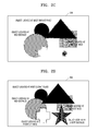
- FIGS. 4A and 4B are diagrams for explaining calculation of actual distance information of an object.
- FIGS. 5A and 5B are diagrams illustrating open states of an aperture and images corresponding thereto.
- FIG. 6 is a diagram for explaining establishment of an aperture open state-based database.
- FIG. 7 is a view illustrating a shutter speed setting table depending on an aperture open state.
- FIGS. 8A to 8C are diagrams for explaining calculation of actual size information of an object.
- FIGS. 9 to 14 are flowcharts illustrating operations of an image processing method according to an exemplary embodiment.
- FIG. 1 is a block diagram illustrating an image processing apparatus 100 according to an exemplary embodiment.
- the image processing apparatus 100 includes an image-capturing unit 110 , an image signal processor 120 , a storage 130 , a digital signal processor 200 , and a display 300 .
- Light from an object passes through a zoom lens 111 and a focus lens 113 , which are an optical system of the image-capturing unit 110 , and an amount of the light is adjusted by an opened/closed degree of an aperture 115 , and then an image of the object is formed on a light-receiving surface of an image-capturing device 117 .
- the image formed on the light-receiving surface of the image-capturing device 117 is converted into an electric image signal by a photo-electric conversion process.
- Examples of the image-capturing device 117 include a charge-coupled device (CCD), and a complementary metal oxide semiconductor (CMOS) image sensor.
- the aperture 115 becomes an open state during a normal state or when an auto-focusing algorithm that is performed by receiving a first release signal formed by pressing a release button by half is executed, and the aperture 115 may execute an exposure process by receiving a second release signal formed by softly pressing the release button.
- the positions, etc. of the zoom lens 111 and the focus lens 113 are controlled by a zoom lens driver 112 and a focus lens driver 114 , respectively. An opening degree, etc.
- the zoom lens driver 112 , the focus lens driver 114 , the aperture driver 116 , and the image-capturing device controller 118 control relevant components according to results operated by the digital signal processor 200 based on exposure information, focus information, etc.
- the image signal processor 120 converts an analog image signal input from the image-capturing device 117 into a digital image signal, and performs various image processes on the converted digital image signal.
- the image signal on which these processes have been performed may be stored in the storage 130 and output to the display 300 , or transmitted to outside under control of the digital signal processor 200 .
- the image signal processor 120 improves image quality by performing signal processes such as auto white balance, auto exposure, gamma correction, etc. in order to convert image data suitable for a human sense of vision, and outputs an image signal having an improved image quality. Also, the image signal processor 120 performs image processes such as color filter array interpolation, a color matrix, color correction, and color enhancement.
- the storage 130 may store a program regarding operations of the image processing apparatus 100 , or store image data or other data regardless of whether power is supplied.
- the digital signal processor 200 performs an operation according to an operating system and an application stored in the storage 130 , stores the operation results, and allows the image processing apparatus 100 to operate by controlling a relevant component according to the operation result.
- the digital signal processor 200 according to an exemplary embodiment allows the focus lens 113 to sequentially move from infinity to a short distance by controlling the focus lens driver 114 , calculates relative distance information of objects included in an image, actual distance information of the objects, and actual size information of the objects, and displays the same on the display 300 .
- the digital signal processor 200 operates an opening degree of the aperture 115 from a maximum opening to a minimum opening by controlling the aperture driver 116 , calculates relative distance information of objects included in an image, actual distance information of the objects, and actual size information of the objects, and displays the same on the display 300 .
- the digital signal processor 200 may include a distance information calculator 210 and a size information calculator 220 .
- FIGS. 2A to 2D are diagrams for explaining calculation of relative distance information of an object.
- the distance information calculator 210 sets so that a focal length of the focus lens 113 may be infinity by controlling the focus lens driver 114 .
- the focus lens driver 114 may be an actuator that moves the focus lens 113 , and for example, may be a voice coil motor.
- a screen illustrated in FIG. 2A is displayed on the display 300 .
- the distance information calculator 210 moves the focus lens 113 from infinity to a short distance by controlling the focus lens driver 114 , overlaps and stores frames at which an object is focused.
- FIGS. 2B and 2C are diagrams illustrating objects focused at a most distant place and a mid-distance while moving the focus lens 113 to a short distance.
- focused objects may be selectively stored while a frame is stored. For example, in the case where two or more objects focused at a mid-distance exist as illustrated in FIG. 2C , when arbitrary one object is selected, only a relevant focused object frame may be stored.
- the distance information calculator 210 synthesizes overlapping image frames in one frame and displays the same, and simultaneously, displays relative distance information of objects focused at different locations of the focus lens 113 based on an object focused at an arbitrary location of the focus lens 113 . For example, based on an object focused at a most distant place of the focus lens 113 as illustrated in FIG. 2B , focused locations of other objects may be displayed as a most distance place, a mid-distance, a short distance, etc. as illustrated in FIG. 2D . In the case of FIG. 2D , it is known that relative distance information for all objects are included.
- FIG. 3 is a diagram for explaining establishment of a focus lens location-based database
- FIGS. 4A and 4B are diagrams for explaining calculation of actual distance information of an object.
- a database is established and stored in the storage 130 first.
- the database denotes a database that maps actual distance information from the image processing apparatus 100 to an object to each movement location of the focus lens 113 , and may be established by experiment.
- the focus lens 113 is moved from infinity to a short distance on a step basis by the focus lens driver 114 , and a distance of an object is mapped to a step when focusing is performed and the location of the focus lens 113 is fixed.
- steps of the focus lens driver 114 are in a range from about 0 to about 255
- distances of an object ranging from about 0.9 to about 104 m may be allocated to respective steps.
- the distance information calculator 210 moves the focus lens 113 from infinity to a short distance by controlling the focus lens driver 114 , overlaps and stores focused frames. In this case, whenever each object is focused, actual distance information mapped to a step of the focus lens driver 114 may be obtained.
- the distance information calculator 210 displays a synthesis frame that synthesizes overlapping image frames in one frame, and simultaneously, detects actual distance information mapped to each focused object from the database, and displays the same on the display 300 .
- FIG. 4A illustrates objects having different distances from the image processing apparatus 100
- FIG. 4B illustrates displaying actual distance information of respective objects generated by the distance information calculator 210 inside a synthesis frame.
- FIGS. 5A and 5B are diagrams illustrating open states of the aperture 115 and images corresponding thereto.
- a depth of field denotes a range recognized as being focused in an image. That is, a depth of field determines whether to allow only an intended object to be focused with a background of the object not focused (out of focus), or whether to allow not only the intended object but also the background of the object to be focused (pan focus).
- FIG. 5A is a diagram illustrating open states of the aperture 115 , in which an amount of light passing through the lens reduces from left to right, resulting in deep depth of field recognized as being focused.
- f/2.8 may be a state under which the aperture 115 is open maximally
- f/22 may be a state under which the aperture 115 is open minimally. That is, a depth recognized as being focused may change depending on an opening degree of the aperture 115 .
- FIG. 5B-1 is an image captured with an opening degree of the aperture 115 set to f/22 of FIG. 5A
- FIG. 5B-2 is an image captured with an opening degree of the aperture 115 set to f/2.8 of FIG. 5A . From this, it is known that the smaller an opening degree of the aperture 115 is small, the deeper a depth of field recognized as being focused does.
- the digital signal processor 200 may extract distance information of an object by detecting an opening degree of the aperture 115 via the aperture driver 116 based on this principle.
- the distance information calculator 210 operates an opening degree of the aperture 115 from a maximum opening to a minimum opening by controlling the aperture driver 116 , and overlaps and stores frames including an object focused under each open state.
- the distance information calculator 210 may selectively store focused objects when storing a frame. For example, in the case where an open state of the aperture 115 is f/5.6 and two or more focused objects exist, when arbitrary one object is selected, only a relevant focused object frame may be stored. Also, when all objects are selected, relevant focused object frames may be stored.
- the distance information calculator 210 displays a synthesis frame that synthesizes overlapping image frames in one frame, and simultaneously, displays relative distance information of objects focused at different open states of the aperture 115 based on an object focused under an arbitrary open state of the aperture 115 .
- FIG. 6 is a diagram for explaining establishment of an aperture open state-based database.
- a database is established and stored in the storage 130 first.
- the database denotes a database that maps actual distance information from the image processing apparatus 100 to an object to each open state of the aperture 115 , and may be established by experiment.
- an opening degree of the aperture 115 is operated from a maximum opening to a minimum opening by the aperture driver 116 , and a distance of an object is mapped to an open state of the aperture 115 under which focusing is performed.
- a distance of an object corresponding to each open state may be allocated to about 1 to about 30 m.
- an open state of the aperture 115 and a distance of an object are shown as an exemplary embodiment, and may extend or change.
- the distance information calculator 210 operates an opening degree of the aperture 115 from the maximum opening to the minimum opening by controlling the aperture driver 116 , and overlaps and stores focused frames. In this case, whenever each object is focused, actual distance information mapped to an open state of the aperture 115 may be obtained.
- the distance information calculator 210 displays a synthesis frame that synthesizes overlapping image frames in one frame, and simultaneously, detects actual distance information mapped to each focused object from the database, and displays the same on the display 300 .
- FIG. 4A illustrates objects having different distances from the image processing apparatus 100
- FIG. 4B illustrates displaying actual distance information of respective objects generated by the distance information calculator 210 inside a synthesis frame.
- the aperture 115 and a shutter speed may be used.
- the shutter speed represents a speed of opening and closing a shutter one time.
- the shutter speed is related to a time for which the image-capturing device 117 is exposed to light and means that different shutter speeds should be applied depending on an amount of light, movement of an object, etc. That is, when the above-mentioned opening degree of the aperture 115 and shutter speed are used together, image information and distance information of better image quality may be obtained. For example, when f/22 is used to deepen a depth of field, an image in which an object located far away is focused may be obtained, but an amount of light is relatively small and thus a relatively dark image is obtained. Therefore, an effective image may be obtained by slowing a shutter speed and thus increasing an amount of light.
- FIG. 7 is a view illustrating a shutter speed setting table depending on an aperture open state. From FIG. 7 , a shutter speed value changes depending on an open state of the aperture 115 . Particularly, as an aperture value representing an open state of the aperture 115 increases, an open state of the aperture 115 gradually reduces, and thus when an aperture value is small (for example, f/2.8), a shutter speed may be set fast (for example, 1/120), and when an aperture value is large (for example, f/5.6), a shutter speed may be set slow (for example, 1/30). When the aperture value and the shutter speed value are set as described above, an image of the same exposure may be obtained.
- an aperture value representing an open state of the aperture 115 increases, an open state of the aperture 115 gradually reduces, and thus when an aperture value is small (for example, f/2.8), a shutter speed may be set fast (for example, 1/120), and when an aperture value is large (for example, f/5.6), a shutter speed may be set slow (for example,
- FIGS. 8A to 8C are diagrams for explaining calculation of actual size information of an object.
- FIG. 8A illustrates a state under which the image processing apparatus 100 captures an object A and an object B
- FIG. 8B illustrates a state in which captured object A and object B are displayed on the display 300
- object detection depends on only an absolute size of an object displayed on the display 300 .
- the object B for example, a person
- the object A for example, a pet
- size correction by an actual distance value between an object at a short distance and an object located far away is required, and object detection should be performed by reflecting the size correction.
- the object A is recognized as larger on the display 300 . That is, in the case where object detection is performed based on a predetermined size on the display 300 , the object A may be detected but the object B may not be detected. However, when a fact that the object B is greater than the object A actually is taken into account, effective information should be obtained by surely using distance information. Therefore, when object detection is performed by using actual distance information of an object, more effective data may be extracted.
- the size information calculator 220 calculates actual size information of an object by using actual distance information of the object and displays the same on the display 300 .
- the size information calculator 220 calculates a size of each object inside a synthesis frame illustrated in FIG. 8C . For example, it is assumed that a size of the object A on a screen has been calculated as 1 cm, and a size of the object B on the screen has been calculated as 2 ⁇ 3 cm.
- the size information calculator 220 obtains actual distance information of the object A and the object B from the distance information calculator 210 .
- the size information calculator 220 has obtained actual distance information of the object A as 10 m and actual distance information of the object B as 30 m from the distance information calculator 210 .
- an actual distance information ratio of the object B may be calculated based on the actual distance information of the object A, and the ratio is 1:3. That is, the actual distance information of the object B is three times-farther than the actual distance information of the object A.
- the size information calculator 220 may obtain that an actual size of the object B and an actual size of the object A. From this, in the case where a size of the object A is 1 cm in a synthesis frame, an actual size of the object A becomes 10 cm, and in the case where a size of the object B is 2 ⁇ 3 cm in a synthesis frame, an actual size of the object B becomes 20 cm and consequently, the object B is bigger than the object A. Therefore, the size information calculator 220 may display that the object B is bigger than the object A on the display 300 .
- distance information and size information of the object inside an image frame may be calculated without a separate distance measurement algorithm or size measurement algorithm.
- the image processing method according to an exemplary embodiment may be performed inside the image processing apparatus 100 illustrated in FIG. 1 .
- a primary algorithm of the operating method may be performed inside the digital signal processor 200 with assistance of peripheral components inside the apparatus.
- descriptions of portions that are the same as those in FIGS. 1 to 8 are omitted.
- FIG. 9 is a flowchart illustrating operations of a method of calculating relative distance information of an object according to an exemplary embodiment in an image processing method according to an exemplary embodiment.
- the digital signal processor 200 performs operation S 910 of sequentially moving the focus lens 113 from infinity to a short distance by controlling the focus lens driver 114 .
- the digital signal processor 200 performs operation S 920 of overlapping and storing frames including an object focused at each movement location of the focus lens 113 while sequentially moving the focus lens 113 from infinity to a short distance.
- the focused objects may be selectively stored when a frame is stored. For example, in the case where two or more objects focused at a mid-distance exist, when an arbitrary one object is selected, only a relevant focused object frame may be stored. Alternatively, when all objects are selected, all focused object frames may be stored.
- the digital signal processor 200 performs operation S 930 of displaying a synthesis frame that synthesizes overlapping frames in one frame, and simultaneously, calculating relative distance information of objects focused at other locations of the focus lens 113 based on an object focused at an arbitrary location of the focus lens 113 , and displaying the calculated relative distance information in the synthesis frame.
- focused locations of other objects may be displayed as a short distance, a mid-distance, and a farthest distance based on an object focused at a short distance by the focus lens 113 . Therefore, distance information of all objects focused inside the synthesis frame may be displayed.
- FIG. 10 is a flowchart illustrating operations of a method of calculating actual distance information of an object according to an exemplary embodiment in an image processing method according to an exemplary embodiment.
- the digital signal processor 200 performs operation S 1010 of establishing a database that maps actual distance information from the image processing apparatus 100 to an object to each movement location of the focus lens 113 .
- the focus lens 113 is moved from infinity to a short distance on each step basis by the focus lens driver 114 , and a distance of an object is mapped to a step when focusing is performed and a location of the focus lens 113 is fixed.
- the digital signal processor 200 performs operation S 1020 of sequentially moving the focus lens 113 from infinity to a short distance by controlling the focus lens driver 114 .
- the digital signal processor 200 performs operation S 1030 of overlapping and storing frames including an object focused at each movement location of the focus lens 113 while sequentially moving the focus lens 113 from infinity to a short distance.
- the digital signal processor 200 performs operation S 1040 of displaying a synthesis frame that synthesizes overlapping frames in one frame, and simultaneously, detecting actual distance information mapped to a step of the focus lens driver 114 when each object is focused from the database, and displaying the actual distance information in the synthesis frame.
- FIG. 11 is a flowchart illustrating operations of a method of calculating actual size information of an object according to an exemplary embodiment in the image processing method according to an exemplary embodiment.
- the digital signal processor 200 performs operation S 1110 of establishing a database that maps actual distance information from the image processing apparatus 100 to an object to each movement location of the focus lens 113 .
- the digital signal processor 200 performs operation S 1120 of sequentially moving the focus lens 113 from infinity to a short distance by controlling the focus lens driver 114 .
- the digital signal processor 200 performs operation of overlapping and storing frames including an object focused at each movement location of the focus lens 113 while sequentially moving the focus lens 113 from infinity to a short distance.
- the digital signal processor 200 performs operation S 1130 of displaying a synthesis frame that synthesizes overlapping frames in one frame, and simultaneously, calculating a size of each object inside the synthesis frame.
- the digital signal processor 200 perform operation S 1140 of detecting and obtaining actual distance information mapped to a step of the focus lens driver 114 when each object is focused from the database.
- the digital signal processor 200 performs operation S 1160 of calculating an actual distance information ratio of focused other objects based on actual distance information mapped to a focused arbitrary object.
- the digital signal processor 200 performs operation S 1170 of calculating actual size information of objects by applying the calculated ratio to a size of each object, and displaying the actual size information in the synthesis frame.
- FIG. 12 is a flowchart illustrating operations of a method of calculating relative distance information of an object according to another exemplary embodiment in an image processing method according to an exemplary embodiment.
- the digital signal processor 200 performs operation S 1210 of operating an opening degree of the aperture 115 from a maximum opening to a minimum opening by controlling the aperture driver 116 .
- the digital signal processor 200 performs operation S 1220 of overlapping and storing frames including an object focused under each open state of the aperture 115 while operating the opening degree of the aperture 115 from the maximum opening to the minimum opening.
- focused objects may be selectively stored when a frame is stored. For example, in the case where two or more objects focused at a mid-distance exist, when an arbitrary one object is selected, only a relevant focused object frame may be stored. Alternatively, when all objects are selected, focused all object frames may be stored.
- the digital signal processor 200 performs operation S 1230 of displaying a synthesis frame that synthesizes overlapping frames in one frame, and simultaneously, calculating relative distance information of objects focused under other open states of the aperture 115 based on an object focused under an arbitrary open state of the aperture 115 and displaying the relative distance information in the synthesis frame.
- FIG. 13 is a flowchart illustrating operations of a method of calculating actual distance information of an object according to another exemplary embodiment in an image processing method according to an exemplary embodiment.
- the digital signal processor 200 performs operation S 1310 of establishing a database that maps actual distance information from the image processing apparatus 100 to an object to each open state of the aperture 115 .
- the aperture 115 is operated from a maximum opening to a minimum opening by the aperture driver 116 , and a distance of an object is mapped to an open state of the aperture 115 under which focusing is performed.
- the digital signal processor 200 When the establishment of the database is completed, the digital signal processor 200 performs operation S 1320 of operating the aperture 115 from a maximum opening to a minimum opening by controlling the aperture driver 116 .
- the digital signal processor 200 performs operation S 1330 of overlapping and storing frames including an object focused under each open state of the aperture 115 while operating the aperture 115 from the maximum opening to the minimum opening.
- the digital signal processor 200 performs operation S 1340 of displaying a synthesis frame that synthesizes overlapping frames in one frame, and simultaneously, detecting actual distance information mapped to an open state of the aperture 115 when each object is focused from the database, and displaying the actual distance information.
- the aperture 115 and the shutter speed may be used for calculation of distance information of an object.
- FIG. 14 is a flowchart illustrating operations of a method of calculating actual size information of an object according to another exemplary embodiment in an image processing method according to an exemplary embodiment.
- the digital signal processor 200 performs operation S 1410 of establishing a database that maps actual distance information from the image processing apparatus 100 to an object to each open state of the aperture 115 .
- the digital signal processor 200 performs operation S 1420 of operating the aperture 115 from a maximum opening to a minimum opening by controlling the aperture driver 116 .
- the digital signal processor 200 performs operation of overlapping and storing frames including an object focused under each open state of the aperture 115 while operating the aperture 115 from the maximum opening to the minimum opening.
- the digital signal processor 200 performs operation S 1430 of displaying a synthesis frame that synthesizes overlapping frames in one frame, and simultaneously, calculating a size of each object inside the synthesis frame.
- the digital signal processor 200 performs operation S 1440 of detecting and obtaining actual distance information mapped to an open state of the aperture 115 when each object is focused from the database.
- the digital signal processor 200 performs operation S 1460 of calculating an actual distance information ratio of focused other objects based on actual distance information mapped to a focused arbitrary object.
- the digital signal processor 200 performs operation S 1470 of calculating actual size information of objects by applying the calculated ratio to a size of each object, and displaying the actual size information in the synthesis frame.
- the inventive concept relates to an apparatus and a method of calculating distance information and size information of an object within an image frame.
Abstract
Description
Claims (16)
Applications Claiming Priority (3)
| Application Number | Priority Date | Filing Date | Title |
|---|---|---|---|
| KR1020130098606A KR102066938B1 (en) | 2013-08-20 | 2013-08-20 | Apparatus and method for processing image |
| KR10-2013-0098606 | 2013-08-20 | ||
| PCT/KR2014/003287 WO2015026041A1 (en) | 2013-08-20 | 2014-04-16 | Image processing device and method |
Publications (2)
| Publication Number | Publication Date |
|---|---|
| US20160198082A1 US20160198082A1 (en) | 2016-07-07 |
| US9648224B2 true US9648224B2 (en) | 2017-05-09 |
Family
ID=52483793
Family Applications (1)
| Application Number | Title | Priority Date | Filing Date |
|---|---|---|---|
| US14/908,315 Active US9648224B2 (en) | 2013-08-20 | 2014-04-16 | Apparatus and method of processing image |
Country Status (3)
| Country | Link |
|---|---|
| US (1) | US9648224B2 (en) |
| KR (1) | KR102066938B1 (en) |
| WO (1) | WO2015026041A1 (en) |
Families Citing this family (3)
| Publication number | Priority date | Publication date | Assignee | Title |
|---|---|---|---|---|
| US20160295122A1 (en) * | 2015-04-03 | 2016-10-06 | Canon Kabushiki Kaisha | Display control apparatus, display control method, and image capturing apparatus |
| US9906181B2 (en) * | 2015-04-23 | 2018-02-27 | Samsung Electro-Mechanics Co., Ltd. | Voice coil motor driver and camera module having the same |
| US9800773B2 (en) * | 2015-06-25 | 2017-10-24 | Motorola Mobility Llc | Digital camera apparatus with dynamically customized focus reticle and automatic focus reticle positioning |
Citations (16)
| Publication number | Priority date | Publication date | Assignee | Title |
|---|---|---|---|---|
| JP2003195148A (en) | 2001-12-26 | 2003-07-09 | Fuji Photo Optical Co Ltd | Subject distance display device |
| US20070285528A1 (en) * | 2006-06-09 | 2007-12-13 | Sony Corporation | Imaging apparatus, control method of imaging apparatus, and computer program |
| US20080189036A1 (en) * | 2007-02-06 | 2008-08-07 | Honeywell International Inc. | Method and system for three-dimensional obstacle mapping for navigation of autonomous vehicles |
| US20080297639A1 (en) * | 2007-06-01 | 2008-12-04 | Matsushita Electric Industrial Co., Ltd. | Camera system |
| US20090109304A1 (en) * | 2007-10-29 | 2009-04-30 | Ricoh Company, Limited | Image processing device, image processing method, and computer program product |
| KR20090056592A (en) | 2007-11-30 | 2009-06-03 | 삼성디지털이미징 주식회사 | Apparatus for processing digital image and method for controlling thereof |
| US20100033617A1 (en) * | 2008-08-05 | 2010-02-11 | Qualcomm Incorporated | System and method to generate depth data using edge detection |
| US20100165152A1 (en) * | 2008-12-30 | 2010-07-01 | Massachusetts Institute Of Technology | Processing Images Having Different Focus |
| US20100171815A1 (en) | 2009-01-02 | 2010-07-08 | Hyun-Soo Park | Image data obtaining method and apparatus therefor |
| JP2011053299A (en) | 2009-08-31 | 2011-03-17 | Canon Inc | Lens apparatus |
| US20110157400A1 (en) * | 2009-12-24 | 2011-06-30 | Samsung Electronics Co., Ltd. | Photographing apparatus and method of displaying graphic for user to estimate the real size of object |
| KR20110104748A (en) | 2010-03-17 | 2011-09-23 | 삼성테크윈 주식회사 | Digital imaging apparatus and controlling method of the same |
| US20120148109A1 (en) * | 2010-06-17 | 2012-06-14 | Takashi Kawamura | Distance estimation device, distance estimation method, integrated circuit, and computer program |
| JP2012156747A (en) | 2011-01-26 | 2012-08-16 | Casio Comput Co Ltd | Imaging apparatus, image composition method, and program |
| US20130033578A1 (en) * | 2010-02-19 | 2013-02-07 | Andrew Augustine Wajs | Processing multi-aperture image data |
| KR20130017918A (en) | 2011-08-12 | 2013-02-20 | 엘지이노텍 주식회사 | Camera module and method for measuring distance using the same |
Family Cites Families (2)
| Publication number | Priority date | Publication date | Assignee | Title |
|---|---|---|---|---|
| JP2005181034A (en) * | 2003-12-18 | 2005-07-07 | Casio Comput Co Ltd | Size measurement device and program |
| JP2007208745A (en) * | 2006-02-02 | 2007-08-16 | Victor Co Of Japan Ltd | Monitoring device and monitoring method |
-
2013
- 2013-08-20 KR KR1020130098606A patent/KR102066938B1/en active IP Right Grant
-
2014
- 2014-04-16 WO PCT/KR2014/003287 patent/WO2015026041A1/en active Application Filing
- 2014-04-16 US US14/908,315 patent/US9648224B2/en active Active
Patent Citations (18)
| Publication number | Priority date | Publication date | Assignee | Title |
|---|---|---|---|---|
| JP2003195148A (en) | 2001-12-26 | 2003-07-09 | Fuji Photo Optical Co Ltd | Subject distance display device |
| US20070285528A1 (en) * | 2006-06-09 | 2007-12-13 | Sony Corporation | Imaging apparatus, control method of imaging apparatus, and computer program |
| US20080189036A1 (en) * | 2007-02-06 | 2008-08-07 | Honeywell International Inc. | Method and system for three-dimensional obstacle mapping for navigation of autonomous vehicles |
| US20080297639A1 (en) * | 2007-06-01 | 2008-12-04 | Matsushita Electric Industrial Co., Ltd. | Camera system |
| US20090109304A1 (en) * | 2007-10-29 | 2009-04-30 | Ricoh Company, Limited | Image processing device, image processing method, and computer program product |
| KR20090056592A (en) | 2007-11-30 | 2009-06-03 | 삼성디지털이미징 주식회사 | Apparatus for processing digital image and method for controlling thereof |
| US8477232B2 (en) * | 2008-08-05 | 2013-07-02 | Qualcomm Incorporated | System and method to capture depth data of an image |
| US20100033617A1 (en) * | 2008-08-05 | 2010-02-11 | Qualcomm Incorporated | System and method to generate depth data using edge detection |
| US20100165152A1 (en) * | 2008-12-30 | 2010-07-01 | Massachusetts Institute Of Technology | Processing Images Having Different Focus |
| US20100171815A1 (en) | 2009-01-02 | 2010-07-08 | Hyun-Soo Park | Image data obtaining method and apparatus therefor |
| KR20100080704A (en) | 2009-01-02 | 2010-07-12 | 삼성전자주식회사 | Method and apparatus for obtaining image data |
| JP2011053299A (en) | 2009-08-31 | 2011-03-17 | Canon Inc | Lens apparatus |
| US20110157400A1 (en) * | 2009-12-24 | 2011-06-30 | Samsung Electronics Co., Ltd. | Photographing apparatus and method of displaying graphic for user to estimate the real size of object |
| US20130033578A1 (en) * | 2010-02-19 | 2013-02-07 | Andrew Augustine Wajs | Processing multi-aperture image data |
| KR20110104748A (en) | 2010-03-17 | 2011-09-23 | 삼성테크윈 주식회사 | Digital imaging apparatus and controlling method of the same |
| US20120148109A1 (en) * | 2010-06-17 | 2012-06-14 | Takashi Kawamura | Distance estimation device, distance estimation method, integrated circuit, and computer program |
| JP2012156747A (en) | 2011-01-26 | 2012-08-16 | Casio Comput Co Ltd | Imaging apparatus, image composition method, and program |
| KR20130017918A (en) | 2011-08-12 | 2013-02-20 | 엘지이노텍 주식회사 | Camera module and method for measuring distance using the same |
Non-Patent Citations (2)
| Title |
|---|
| International Search Report (PCT/ISA/210) issued Jul. 10, 2014, issued in International Application No. PCT/KR2014/003287. |
| Written Opinion (PCT/ISA/237) issued Jul. 10, 2014, issued in International Application No. PCT/KR2014/003287. |
Also Published As
| Publication number | Publication date |
|---|---|
| WO2015026041A1 (en) | 2015-02-26 |
| KR102066938B1 (en) | 2020-01-16 |
| US20160198082A1 (en) | 2016-07-07 |
| KR20150021350A (en) | 2015-03-02 |
Similar Documents
| Publication | Publication Date | Title |
|---|---|---|
| JP7003238B2 (en) | Image processing methods, devices, and devices | |
| JP5621325B2 (en) | FOCUS CONTROL DEVICE, FOCUS CONTROL METHOD, LENS DEVICE, FOCUS LENS DRIVING METHOD, AND PROGRAM | |
| US20120105590A1 (en) | Electronic equipment | |
| JP4578334B2 (en) | In-focus position determining apparatus and method for imaging lens | |
| CN102801910A (en) | Image sensing device | |
| US20080252744A1 (en) | Auto-focus apparatus, image-pickup apparatus, and auto-focus method | |
| EP3346308A1 (en) | Detection device, detection method, detection program, and imaging device | |
| CN104641275B (en) | The control method that imaging control apparatus, imaging device and imaging control apparatus perform | |
| JP2012042833A5 (en) | ||
| JP6739064B1 (en) | Imaging device | |
| US10356384B2 (en) | Image processing apparatus, image capturing apparatus, and storage medium for storing image processing program | |
| JP2008116526A (en) | Device and method for processing microscope image | |
| JP2007003656A (en) | Apparatus for determining focal position of imaging lens and method thereof | |
| US9648224B2 (en) | Apparatus and method of processing image | |
| US20100086292A1 (en) | Device and method for automatically controlling continuous auto focus | |
| CN103988107A (en) | Imaging device, method for controlling same, and program | |
| CN106878604B (en) | Image generation method based on electronic equipment and electronic equipment | |
| KR20150014226A (en) | Electronic Device And Method For Taking Images Of The Same | |
| JP2009219085A (en) | Imaging apparatus | |
| JP6778340B2 (en) | Imaging device, imaging method, and program | |
| JP2013118472A (en) | Image processing apparatus, imaging apparatus and image processing program | |
| TW201643537A (en) | Image capture device and focus method | |
| US11880991B2 (en) | Imaging apparatus including depth information at first or second spatial resolution at different regions in the image | |
| JP5769534B2 (en) | Imaging apparatus, imaging method, and program | |
| KR20110003891A (en) | Space detecting apparatus for image pickup apparatus using auto focusing and the method thereof |
Legal Events
| Date | Code | Title | Description |
|---|---|---|---|
| AS | Assignment |
Owner name: HANWHA TECHWIN CO., LTD., KOREA, REPUBLIC OF Free format text: ASSIGNMENT OF ASSIGNORS INTEREST;ASSIGNORS:CHOI, MOON GYU;KIM, JI HONG;YOON, SEOK JUN;REEL/FRAME:037629/0972 Effective date: 20160120 |
|
| STCF | Information on status: patent grant |
Free format text: PATENTED CASE |
|
| AS | Assignment |
Owner name: HANWHA AEROSPACE CO., LTD., KOREA, REPUBLIC OF Free format text: CHANGE OF NAME;ASSIGNOR:HANWHA TECHWIN CO., LTD;REEL/FRAME:046927/0019 Effective date: 20180401 |
|
| AS | Assignment |
Owner name: HANWHA AEROSPACE CO., LTD., KOREA, REPUBLIC OF Free format text: CORRECTIVE ASSIGNMENT TO CORRECT THE APPLICATION NUMBER 10/853,669. IN ADDITION PLEASE SEE EXHIBIT A PREVIOUSLY RECORDED ON REEL 046927 FRAME 0019. ASSIGNOR(S) HEREBY CONFIRMS THE CHANGE OF NAME;ASSIGNOR:HANWHA TECHWIN CO., LTD.;REEL/FRAME:048496/0596 Effective date: 20180401 |
|
| AS | Assignment |
Owner name: HANWHA TECHWIN CO., LTD., KOREA, REPUBLIC OF Free format text: ASSIGNMENT OF ASSIGNORS INTEREST;ASSIGNOR:HANWHA AEROSPACE CO., LTD.;REEL/FRAME:049013/0723 Effective date: 20190417 |
|
| MAFP | Maintenance fee payment |
Free format text: PAYMENT OF MAINTENANCE FEE, 4TH YEAR, LARGE ENTITY (ORIGINAL EVENT CODE: M1551); ENTITY STATUS OF PATENT OWNER: LARGE ENTITY Year of fee payment: 4 |
|
| AS | Assignment |
Owner name: HANWHA VISION CO., LTD., KOREA, REPUBLIC OF Free format text: CHANGE OF NAME;ASSIGNOR:HANWHA TECHWIN CO., LTD.;REEL/FRAME:064549/0075 Effective date: 20230228 |