US964713A - Auxiliary car-coupling. - Google Patents
Auxiliary car-coupling. Download PDFInfo
- Publication number
- US964713A US964713A US39663007A US1907396630A US964713A US 964713 A US964713 A US 964713A US 39663007 A US39663007 A US 39663007A US 1907396630 A US1907396630 A US 1907396630A US 964713 A US964713 A US 964713A
- Authority
- US
- United States
- Prior art keywords
- coupling
- auxiliary
- head
- shoe
- car
- Prior art date
- Legal status (The legal status is an assumption and is not a legal conclusion. Google has not performed a legal analysis and makes no representation as to the accuracy of the status listed.)
- Expired - Lifetime
Links
- 238000010168 coupling process Methods 0.000 title description 32
- 238000005859 coupling reaction Methods 0.000 title description 32
- 230000008878 coupling Effects 0.000 description 31
- 238000010276 construction Methods 0.000 description 5
- 241000320892 Clerodendrum phlomidis Species 0.000 description 1
- 241001274197 Scatophagus argus Species 0.000 description 1
- 230000008520 organization Effects 0.000 description 1
Images
Classifications
-
- B—PERFORMING OPERATIONS; TRANSPORTING
- B61—RAILWAYS
- B61G—COUPLINGS; DRAUGHT AND BUFFING APPLIANCES
- B61G7/00—Details or accessories
- B61G7/14—Safety devices
Definitions
- Thi invention relates to that type of car couplings termed auxiliary 'ar couplings, and which are designed to facilitate the coupling of two cars on short curvcs. particttlarlithosc located in railroad yards.
- auxiliary car coupling designed for use in conncction with the ordinary or conventional car coupling heads in common usc. and comprising means for permitting a couplin to t he ctl'cctcd l-ietwcun opposing couplin; lit-ads where the latter are disalincd by rcason of the curve in the track.
- the improved auxiliary coupling is so cmtstrtnrtcd as to provide for an cxtcnsive shifting or adjustment of the auxiliary coupling head so as to accommodate the same to widely varying conditions.
- a further object of the invention is to provide a construction of auxiliary couple" 2 which iii-altos automatic coupling kvith the regular coupling heads, thereby greatly increasing tho factor of safety to train hands. Also the improved t'OllStlttt'llull is of such a I character that the same possesses utility E lioth in pulling and pushing a coupled car.
- the invention consists in the novel ciinst ruction, coniliinatibn and. arrangement of parts heroinat'tcr more fully do scrihed, illustrated and claimed.
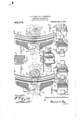
- Figure l is a plan view of an auxiliary car coupling device. illustratinghy dotted lines its use in coupling oppositely located ordinary coupling heads.
- Fig. 2 is a sectional view on the line of Fig. 1.
- Fig. 3 is a front view of the auxiliary coupling head shown in l igl. the view illustrating a shortsection of the supporting shoe upon Fig. 4 is a view similar to Fig. I. showing a.
- Fi 5 is a view similar to Fig. 2,
- the imprm'cd auxiliary coupling device is dcsigned to occupy a position between the two ordinary heads 1 which it is to couple, and referring particula ly to the drawings it will he oh crvcd that the said auxiliary cotzplingdevicc includes in its organization a main supporting shoe t, this supportingrshoe living of an oblong fornnand usually consistiugol a sili locust ing having-anapproximate t'l'tM'tIll shape so as to present a curved front side upon whiclrthc auxiliary coupling head it is mounted.
- the said supporting shot: 4 is designed to he itself rigidly supported and carried by one of the Ol't'llttttl'y or regular coupling heads 1 and to provide for this the shoe l is constructcd at the rear side. tlurcof with an approximately U-shaped couplcr scat designated by the numeral 6 and designed to receive therein practically the ('lllll'L front curl of the regular coupling head Leo as to cmlu'ace not.
- the lior'lyportion of the shoe -l is further provided at its rear side with a holding block 7 fitting in the mouth of the coupling head 1 and provided ith a laterally extending rctainin; arm 8 taking over the guard arm 2 ofthc hcad l, and also provided in ontside thereof with a lt'cnpcr socket. 9 which receives therein the knuckle 3 of the head 1.
- This construction provides for no erl positioning the shoe 4 and also rigidly 01 inn it in place.
- the auxiliary coupling head 5 is of the conventional lUl'lll so as -to automatically couple with the opposing regular coupling head 1, but, it will, of course, be understood 5 that the coupling knuckle 10 of the auxiliary headed in the holding lugs 2; provided It is the purposc of the present invention to provide ⁇ or the l teral shifting of the E auxiliary head 5 so thatit may be adjusted anywhere between the opposite ends of the head 5 is preferably rigid.
- the front side ot the shoe may be formed with a T-shaped guide rib ll with which 1: slidably interlocked a C-yoke E 12 carried by the Fllzlllli or body of the auxiliary coupling head 3, said yoke having its inturned flanges l3 sliding in the groove through a horizontal guide Slflt i in the supporting shoe l and loosely connected at its inner end to slide pin 17 which siidably works in a vertically arranged guide slot 18 formed in the body of the shoe back of the front guide rib 11* thereof.
- the interlocked connee ion between the auxiliary head and the shoe may be effected by providing the front Side of the shoe with a C-yoke l2 with which is slidably interlocked the T-shaped rib 11, as plainly shown in Fig. 3 of the drawings.
- the lateral shifting or adjustment of the auxiliary etnipling head maybe conveniently accomplished by equipping the head with the oppositely arranged shifting rods 1$)1Sl provided at their outer ends with handles 20 and having their inner ends coupled as at 91. as ho ⁇ 'n in llf l and 3. or simply therefor on the upper side of the auxiliary coupling head, as .SllUWlt in Fi k. l of the drawings.
Landscapes
- Engineering & Computer Science (AREA)
- Mechanical Engineering (AREA)
- Footwear And Its Accessory, Manufacturing Method And Apparatuses (AREA)
Description
J. E. ULSH & D. T. GOODMAN. AUXILIARY cm 0002mm.
- NVENTORS Ji /[.5 4:4 wpwm'wm aya APPLICATION I'ILED 001'. 9, 1907.
";rhich said head isslitlalily mounted.
tint-Trina STATES RtTENT OFFlCE.
EOSEPH l. ULSH AND DAVID T. GOODMAN, OF ALTOONA, PENNSYLVANIA.
AUXILIARY CAR-COUPLlNG.
Application filed October S,
T 0 r1?! whom it may concern:
Be it known that we. JOSEPH E. Unsii and IJAYID 'l. Gtiiomuiz, citizens of the United States. residing at Altoona. in the conntv of Blair and State of Pennsylvania, have invented certain new and useful Iniprovcmcnt's in Auxiliary Car-Couplings, of which thefollowing is a specification.
Thi invention relates to that type of car couplings termed auxiliary 'ar couplings, and which are designed to facilitate the coupling of two cars on short curvcs. particttlarlithosc located in railroad yards.
To this end the inventit' n contemplates a simple and practical construction of auxiliary car coupling designed for use in conncction with the ordinary or conventional car coupling heads in common usc. and comprising means for permitting a couplin to t he ctl'cctcd l-ietwcun opposing couplin; lit-ads where the latter are disalincd by rcason of the curve in the track. Furthermore. the improved auxiliary coupling is so cmtstrtnrtcd as to provide for an cxtcnsive shifting or adjustment of the auxiliary coupling head so as to accommodate the same to widely varying conditions.
A further object of the invention is to provide a construction of auxiliary couple" 2 which iii-altos automatic coupling kvith the regular coupling heads, thereby greatly increasing tho factor of safety to train hands. Also the improved t'OllStlttt'llull is of such a I character that the same possesses utility E lioth in pulling and pushing a coupled car.
With these and other objects in \'l('\\'. which will readily appear to those l' zuniliar with thh art, the invention consists in the novel ciinst ruction, coniliinatibn and. arrangement of parts heroinat'tcr more fully do scrihed, illustrated and claimed.
Certain preferred cnihodinn-nts of the invention are shown in the accompanying drawings, in which,
Figure l is a plan view of an auxiliary car coupling device. illustratinghy dotted lines its use in coupling oppositely located ordinary coupling heads. Fig. 2 is a sectional view on the line of Fig. 1. Fig. 3 is a front view of the auxiliary coupling head shown in l igl. the view illustrating a shortsection of the supporting shoe upon Fig. 4 is a view similar to Fig. I. showing a.
t l modified mounting for the auxiliary coupl j Specification of LettersPatent. Patented July 19, 1910.
1907. Serial No. 396,630.
ling head; Fi 5 is a view similar to Fig. 2,
but taken on t e line :B -fi of Fig. 4. Fig. 6
construction of the ordinary car couplings in common use on railway cars, hence for illustrative purposes there are shown by dotted lines in Figs. 1 and l of the drawing the ordinary car coupling heads 1.-1. and for illustrative purposes these heads are shown as of the t:011\'(-';Itti0!1-.i automatic type, each of the saniecnihodying in its construction the usual rigid guard arm 2 and the couplin; knuckle 3. the functions of which are well nndcrstood.
The imprm'cd auxiliary coupling device is dcsigned to occupy a position between the two ordinary heads 1 which it is to couple, and referring particula ly to the drawings it will he oh crvcd that the said auxiliary cotzplingdevicc includes in its organization a main supporting shoe t, this supportingrshoe living of an oblong fornnand usually consistiugol a sili locust ing having-anapproximate t'l'tM'tIll shape so as to present a curved front side upon whiclrthc auxiliary coupling head it is mounted. The said supporting shot: 4 is designed to he itself rigidly supported and carried by one of the Ol't'llttttl'y or regular coupling heads 1 and to provide for this the shoe l is constructcd at the rear side. tlurcof with an approximately U-shaped couplcr scat designated by the numeral 6 and designed to receive therein practically the ('lllll'L front curl of the regular coupling head Leo as to cmlu'ace not. only the knuckle El and thc lt'nuclt'lc pivotal support, but also the guard arni In addition tothc said seat (3 the lior'lyportion of the shoe -l is further provided at its rear side with a holding block 7 fitting in the mouth of the coupling head 1 and provided ith a laterally extending rctainin; arm 8 taking over the guard arm 2 ofthc hcad l, and also provided in ontside thereof with a lt'cnpcr socket. 9 which receives therein the knuckle 3 of the head 1. This construction provides for no erl positioning the shoe 4 and also rigidly 01 inn it in place.
The auxiliary coupling head 5 is of the conventional lUl'lll so as -to automatically couple with the opposing regular coupling head 1, but, it will, of course, be understood 5 that the coupling knuckle 10 of the auxiliary headed in the holding lugs 2; provided It is the purposc of the present invention to provide {or the l teral shifting of the E auxiliary head 5 so thatit may be adjusted anywhere between the opposite ends of the head 5 is preferably rigid.
shoe 4. and to provide for this there is an interlocked elidiug connection between the auxiliary head and the said shoe. This conneetion may be provided in \tll'lOllS ways. For instance, as shown in ltlgs. l and 2 of the drawing, the front side ot the shoe may be formed with a T-shaped guide rib ll with which 1: slidably interlocked a C-yoke E 12 carried by the Fllzlllli or body of the auxiliary coupling head 3, said yoke having its inturned flanges l3 sliding in the groove through a horizontal guide Slflt i in the supporting shoe l and loosely connected at its inner end to slide pin 17 which siidably works in a vertically arranged guide slot 18 formed in the body of the shoe back of the front guide rib 11* thereof. Again, as snow'n in detail Fig. (3 0f the drawing the interlocked connee ion between the auxiliary head and the shoe may be effected by providing the front Side of the shoe with a C-yoke l2 with which is slidably interlocked the T-shaped rib 11, as plainly shown in Fig. 3 of the drawings.
The lateral shifting or adjustment of the auxiliary etnipling head maybe conveniently accomplished by equipping the head with the oppositely arranged shifting rods 1$)1Sl provided at their outer ends with handles 20 and having their inner ends coupled as at 91. as ho\\'n in llf l and 3. or simply therefor on the upper side of the auxiliary coupling head, as .SllUWlt in Fi k. l of the drawings.
\Ve. claim 1. In an auxiliary car coupling, the combination with a main car coupling head, a .wparate Fupportingehoc of an approximately err-went hape and having holding ineanfor engagement with said inuin coup ling head. said shoe being further provided with :1 l ngitudinally arranged guide. an auxiliary shittablo eouplin; lu-ad loosely interlocked directly with the guide ot'the Mlpporting shoe and slidable lengthwise of 7 a a the shoe within the conrured ;ide thereof. provided by the T-shape of the rib 11. Or, 3 as shown in Figs. and 5 of the drawings, E the coupling, head 5'" may be fitted at its rear side with a coupling pin 14 loosely engaged by one end of the coupling link 15 projecting and oppositely located vdrifting connections with said auxiliary couplinghead. i
Q. in an auxiliary cal roupling. the coinhination with a main car coupling head, of a separate approximately crewcnt ahaped supporting hoc having at its rear Side a coupler wat and a holding block provided with a laterally extending retaining arm adapted to overlie the gnardurln ot' the main coupling head. Said shoe being further provided in one side with a keeper ocket to receirc the knuckle of the main coupling head, and a .-hiftahlc auxiliary coupler head car- 'ried by the shoe and aliduble within the concayed sidethereof.
In testimony whereof we hereunto allix onr signatures inthe presenceof two wit Ill-S505.
JOSEPH I). ULSH. DAVID T. GC 'FTBIAN. it nes es Xonuxx l). GEE, l). Lmro (ll..\ruo.\in.-
Priority Applications (1)
| Application Number | Priority Date | Filing Date | Title |
|---|---|---|---|
| US39663007A US964713A (en) | 1907-10-09 | 1907-10-09 | Auxiliary car-coupling. |
Applications Claiming Priority (1)
| Application Number | Priority Date | Filing Date | Title |
|---|---|---|---|
| US39663007A US964713A (en) | 1907-10-09 | 1907-10-09 | Auxiliary car-coupling. |
Publications (1)
| Publication Number | Publication Date |
|---|---|
| US964713A true US964713A (en) | 1910-07-19 |
Family
ID=3033110
Family Applications (1)
| Application Number | Title | Priority Date | Filing Date |
|---|---|---|---|
| US39663007A Expired - Lifetime US964713A (en) | 1907-10-09 | 1907-10-09 | Auxiliary car-coupling. |
Country Status (1)
| Country | Link |
|---|---|
| US (1) | US964713A (en) |
-
1907
- 1907-10-09 US US39663007A patent/US964713A/en not_active Expired - Lifetime
Similar Documents
| Publication | Publication Date | Title |
|---|---|---|
| US1593344A (en) | Automatic coupler for toy cars | |
| US947487A (en) | Coupling. | |
| US938183A (en) | Hose-coupling. | |
| US538533A (en) | Combined car | |
| US1896917A (en) | Automatic train pipe connecter | |
| US1120005A (en) | Draft-gear. | |
| US1568933A (en) | Transition coupling device | |
| US457048A (en) | John green | |
| US1577087A (en) | Car coupler | |
| US1604356A (en) | Transitional car coupling | |
| US1604335A (en) | Car coupler | |
| US572954A (en) | bolger | |
| US947280A (en) | Coupling. | |
| US1930183A (en) | Automatic train pipe connecter | |
| US1109246A (en) | Car-coupling. | |
| US890831A (en) | Automatic train-pipe coupling. | |
| US369502A (en) | Oak coupling | |
| US540057A (en) | Thomas f | |
| US1136079A (en) | Draft-gear attachment. | |
| US1990651A (en) | Drawbar guide for automatic train pipe connecters | |
| US339392A (en) | Car-coupling | |
| US969562A (en) | Draft-gear. | |
| US805744A (en) | Hose-coupling. | |
| US605737A (en) | Car-coupling | |
| US817349A (en) | Emergency knuckle-sleeve. |