US9643345B2 - Resin molding apparatus and resin molding method - Google Patents
Resin molding apparatus and resin molding method Download PDFInfo
- Publication number
- US9643345B2 US9643345B2 US14/123,759 US201214123759A US9643345B2 US 9643345 B2 US9643345 B2 US 9643345B2 US 201214123759 A US201214123759 A US 201214123759A US 9643345 B2 US9643345 B2 US 9643345B2
- Authority
- US
- United States
- Prior art keywords
- mold
- molded product
- lens
- transfer surface
- resin molded
- Prior art date
- Legal status (The legal status is an assumption and is not a legal conclusion. Google has not performed a legal analysis and makes no representation as to the accuracy of the status listed.)
- Active, expires
Links
- 229920005989 resin Polymers 0.000 title claims abstract description 244
- 239000011347 resin Substances 0.000 title claims abstract description 244
- 238000000465 moulding Methods 0.000 title claims abstract description 82
- 238000000034 method Methods 0.000 title claims description 32
- 239000000463 material Substances 0.000 claims abstract description 66
- 230000003287 optical effect Effects 0.000 claims description 42
- 238000010438 heat treatment Methods 0.000 abstract description 14
- 230000001133 acceleration Effects 0.000 description 3
- 230000000694 effects Effects 0.000 description 3
- 230000005489 elastic deformation Effects 0.000 description 3
- 230000015572 biosynthetic process Effects 0.000 description 2
- 230000007423 decrease Effects 0.000 description 2
- 238000005266 casting Methods 0.000 description 1
- 150000001875 compounds Chemical class 0.000 description 1
- 230000003247 decreasing effect Effects 0.000 description 1
- 238000006073 displacement reaction Methods 0.000 description 1
- 239000003822 epoxy resin Substances 0.000 description 1
- 229920000647 polyepoxide Polymers 0.000 description 1
- 239000000758 substrate Substances 0.000 description 1
- 230000003746 surface roughness Effects 0.000 description 1
- 229920001187 thermosetting polymer Polymers 0.000 description 1
Images


Classifications
-
- B—PERFORMING OPERATIONS; TRANSPORTING
- B29—WORKING OF PLASTICS; WORKING OF SUBSTANCES IN A PLASTIC STATE IN GENERAL
- B29C—SHAPING OR JOINING OF PLASTICS; SHAPING OF MATERIAL IN A PLASTIC STATE, NOT OTHERWISE PROVIDED FOR; AFTER-TREATMENT OF THE SHAPED PRODUCTS, e.g. REPAIRING
- B29C37/00—Component parts, details, accessories or auxiliary operations, not covered by group B29C33/00 or B29C35/00
- B29C37/0003—Discharging moulded articles from the mould
-
- B—PERFORMING OPERATIONS; TRANSPORTING
- B29—WORKING OF PLASTICS; WORKING OF SUBSTANCES IN A PLASTIC STATE IN GENERAL
- B29C—SHAPING OR JOINING OF PLASTICS; SHAPING OF MATERIAL IN A PLASTIC STATE, NOT OTHERWISE PROVIDED FOR; AFTER-TREATMENT OF THE SHAPED PRODUCTS, e.g. REPAIRING
- B29C33/00—Moulds or cores; Details thereof or accessories therefor
- B29C33/44—Moulds or cores; Details thereof or accessories therefor with means for, or specially constructed to facilitate, the removal of articles, e.g. of undercut articles
-
- B—PERFORMING OPERATIONS; TRANSPORTING
- B29—WORKING OF PLASTICS; WORKING OF SUBSTANCES IN A PLASTIC STATE IN GENERAL
- B29C—SHAPING OR JOINING OF PLASTICS; SHAPING OF MATERIAL IN A PLASTIC STATE, NOT OTHERWISE PROVIDED FOR; AFTER-TREATMENT OF THE SHAPED PRODUCTS, e.g. REPAIRING
- B29C43/00—Compression moulding, i.e. applying external pressure to flow the moulding material; Apparatus therefor
- B29C43/02—Compression moulding, i.e. applying external pressure to flow the moulding material; Apparatus therefor of articles of definite length, i.e. discrete articles
- B29C43/021—Compression moulding, i.e. applying external pressure to flow the moulding material; Apparatus therefor of articles of definite length, i.e. discrete articles characterised by the shape of the surface
-
- B—PERFORMING OPERATIONS; TRANSPORTING
- B29—WORKING OF PLASTICS; WORKING OF SUBSTANCES IN A PLASTIC STATE IN GENERAL
- B29C—SHAPING OR JOINING OF PLASTICS; SHAPING OF MATERIAL IN A PLASTIC STATE, NOT OTHERWISE PROVIDED FOR; AFTER-TREATMENT OF THE SHAPED PRODUCTS, e.g. REPAIRING
- B29C43/00—Compression moulding, i.e. applying external pressure to flow the moulding material; Apparatus therefor
- B29C43/32—Component parts, details or accessories; Auxiliary operations
- B29C43/50—Removing moulded articles
-
- B—PERFORMING OPERATIONS; TRANSPORTING
- B29—WORKING OF PLASTICS; WORKING OF SUBSTANCES IN A PLASTIC STATE IN GENERAL
- B29C—SHAPING OR JOINING OF PLASTICS; SHAPING OF MATERIAL IN A PLASTIC STATE, NOT OTHERWISE PROVIDED FOR; AFTER-TREATMENT OF THE SHAPED PRODUCTS, e.g. REPAIRING
- B29C45/00—Injection moulding, i.e. forcing the required volume of moulding material through a nozzle into a closed mould; Apparatus therefor
- B29C45/17—Component parts, details or accessories; Auxiliary operations
- B29C45/46—Means for plasticising or homogenising the moulding material or forcing it into the mould
- B29C45/56—Means for plasticising or homogenising the moulding material or forcing it into the mould using mould parts movable during or after injection, e.g. injection-compression moulding
- B29C45/568—Applying vibrations to the mould parts
-
- B—PERFORMING OPERATIONS; TRANSPORTING
- B29—WORKING OF PLASTICS; WORKING OF SUBSTANCES IN A PLASTIC STATE IN GENERAL
- B29D—PRODUCING PARTICULAR ARTICLES FROM PLASTICS OR FROM SUBSTANCES IN A PLASTIC STATE
- B29D11/00—Producing optical elements, e.g. lenses or prisms
- B29D11/00009—Production of simple or compound lenses
- B29D11/00038—Production of contact lenses
- B29D11/00125—Auxiliary operations, e.g. removing oxygen from the mould, conveying moulds from a storage to the production line in an inert atmosphere
- B29D11/00192—Demoulding, e.g. separating lenses from mould halves
-
- B—PERFORMING OPERATIONS; TRANSPORTING
- B29—WORKING OF PLASTICS; WORKING OF SUBSTANCES IN A PLASTIC STATE IN GENERAL
- B29D—PRODUCING PARTICULAR ARTICLES FROM PLASTICS OR FROM SUBSTANCES IN A PLASTIC STATE
- B29D11/00—Producing optical elements, e.g. lenses or prisms
- B29D11/00009—Production of simple or compound lenses
- B29D11/00432—Auxiliary operations, e.g. machines for filling the moulds
-
- B—PERFORMING OPERATIONS; TRANSPORTING
- B29—WORKING OF PLASTICS; WORKING OF SUBSTANCES IN A PLASTIC STATE IN GENERAL
- B29C—SHAPING OR JOINING OF PLASTICS; SHAPING OF MATERIAL IN A PLASTIC STATE, NOT OTHERWISE PROVIDED FOR; AFTER-TREATMENT OF THE SHAPED PRODUCTS, e.g. REPAIRING
- B29C43/00—Compression moulding, i.e. applying external pressure to flow the moulding material; Apparatus therefor
- B29C43/32—Component parts, details or accessories; Auxiliary operations
- B29C43/50—Removing moulded articles
- B29C2043/5092—Removing moulded articles using vibrations means
-
- B—PERFORMING OPERATIONS; TRANSPORTING
- B29—WORKING OF PLASTICS; WORKING OF SUBSTANCES IN A PLASTIC STATE IN GENERAL
- B29L—INDEXING SCHEME ASSOCIATED WITH SUBCLASS B29C, RELATING TO PARTICULAR ARTICLES
- B29L2011/00—Optical elements, e.g. lenses, prisms
- B29L2011/0016—Lenses
Definitions
- the present invention relates to a resin molding apparatus and a resin molding method, and in particular, to a lens molding apparatus and a lens molding method each of which makes it possible to easily and highly accurately mold a lens having a complex shape.
- a conventionally employed lens molding method for molding a lens includes pressing, against a resin material, a mold having a transfer surface for transferring a lens shape and curing the resin material in a state where the mold is pressed against this resin material.
- a molded lens is released from the mold after the resin material is cured.
- the molded lens may be damaged due to adhesion between the lens and the transfer surface.
- Patent Literature 1 discloses a technique for releasing a molded lens from a mold in a compound lens molding apparatus. According to this technique, as illustrated in FIG. 12 , the molded lens is released from a mold 400 , by applying a high-frequency voltage to the mold 400 and vibrating a molding surface 401 of the mold 400 . In this method, the molding surface 401 undergoes elastic deformation and thereby an adhesion strength between the lens and the molding surface 401 can be decreased. Therefore, the molded lens may be safely released from the mold by the method.
- Patent Literature 2 discloses a method for releasing a resin molded product from a mold with use of an ultrasonic wave.
- a molded product 502 is molded by (i) first injecting resin such as epoxy resin having an adhesion effect into a mold 501 which is a casting mold exposed to the atmosphere and which has a cavity 501 a and (ii) curing the resin by heating.
- a flat vibrator 503 is provided so as to be in direct contact with a top surface of the molded product 502 . Then, vibration is directly transferred from the vibrator 503 to the molded product 502 .
- the molded product 502 can be easily peeled off from the mold 501 .
- Patent Literature 3 also discloses a similar technique to that disclosed in Patent Literature 2.
- a technique for accurately processing a thin-wall lens having a complex shape becomes important.
- a thin-wall lens having a largely varying thickness and a large aspherical surface cannot ensure a sufficient rigidity.
- the lens itself may be damaged, for example, deformed or cracked, due to a load that is applied on the lens adhered to a mold at the time when the lens is peeled off from the mold. Accordingly, it is required in molding an aspherical lens or the like, to reduce a resistance between a molded product and a mold as much as possible. Further, in such molding, there is a problem in that mold release is difficult.
- Patent Literatures 1 to 3 because a vibrator is put in direct contact with a molded product and therefore, a whole of the molded product is vibrated. Accordingly, in a case where the molded product is a thin-wall lens, the thin-wall lens tends to be damaged.
- An object of the present invention is to provide a resin molding apparatus and a resin molding method each of which makes it possible to easily and highly accurately mold a resin molded product.
- a resin molding apparatus of the present invention includes: a first mold having a first transfer surface for transferring a predetermined shape to a resin material; a second mold having a second transfer surface for transferring a predetermined shape to the resin material, the second transfer surface being opposed to the first transfer surface; moving means that shifts a relative position of the first mold and the second mold; curing means that cures the resin material so as to form a resin molded product, the resin material having been supplied between the first transfer surface and the second transfer surface; and first vibration applying means that applies vibration from a side surface of the first mold so as to form a gap at least at a part between the first transfer surface and the resin molded product.
- a resin material supplied between the first transfer surface of the first mold and the second transfer surface of the second mold is cured by curing means, so that a resin molded product is formed.
- vibration is applied by the first vibration applying means from a side surface of the first mold and thereby, a gap is formed at least at a part between the first transfer surface and the resin molded product.
- This gap serves as a starting point from which the resin molded product and the first transfer surface are separated from each other.
- the vibration is applied from the side surface of the first mold, only part of the first mold is vibrated. As described above, the vibration is indirectly applied to the resin molded product.
- a resin molding apparatus of the present invention includes: a base plate; a mold having a transfer surface for transferring a predetermined shape to a resin material; moving means that shifts a relative position of the base plate and the mold; curing means that cures the resin material so as to form a resin molded product, the resin material having been supplied between the base plate and the transfer surface; and first vibration applying means that applies vibration from a side surface of the mold so as to form a gap at least at a part between the transfer surface and the resin molded product.
- a resin material supplied between the base plate and the transfer surface of the mold is cured by curing means, so that a resin molded product is formed.
- vibration is applied by the first vibration applying means from a side surface of the mold and thereby, a gap is formed at least at a part between the transfer surface and the resin molded product.
- This gap serves as a starting point from which the resin molded product and the transfer surface are separated from each other.
- the vibration is applied from the side surface of the mold, only part of the mold is vibrated. As described above, the vibration is indirectly applied to the resin molded product.
- a resin molding method of the present invention includes the steps of: (a) curing a resin material so as to form a resin molded product, the resin material having been supplied between a first transfer surface of a first mold and a second transfer surface of a second mold; (b) separating the first transfer surface from the resin molded product; (c) removing the resin molded product from the second mold; and (d) applying vibration from a side surface of the first mold between the steps (a) and (b) so as to form a gap at least at a part between the first transfer surface and the resin molded product.
- the resin material supplied between the first transfer surface of the first mold and the second transfer surface of the second mold is cured by curing means, so that a resin molded product is formed.
- vibration is applied from a side surface of the first mold and thereby, a gap is formed at least at a part between the first transfer surface and the resin molded product. This gap serves as a starting point from which the resin molded product and the first transfer surface are separated from each other in the step (b) of separating the first transfer surface from the resin molded product.
- the vibration is applied from the side surface of the first mold, only part of the first mold is vibrated. As described above, the vibration is indirectly applied to the resin molded product. Therefore, as compared to a conventional arrangement in which a whole transfer surface of a mold is vibrated, a load on the resin molded product can be reduced when the vibration is applied. Consequently, the resin molded product and the first transfer surface can be easily separated from each other. Therefore, it is possible to provide a resin molding method that makes it possible to easily and highly accurately mold a resin molded product.
- a resin molding method of the present invention includes the steps of: (a) curing a resin material so as to form a resin molded product, the resin material having been supplied between a base plate and a transfer surface of a mold; (b) separating the transfer surface from the resin molded product; (c) removing the resin molded product from the base plate; and (d) applying vibration to the mold by applying vibration from a side surface of the mold between the steps (a) and (b) so as to form a gap at least at a part between the transfer surface and the resin molded product.
- the resin material supplied between the base plate and the transfer surface of the mold is cured by curing means, so that a resin molded product is formed.
- vibration is applied from a side surface of the mold and thereby, a gap is formed at least at a part between the transfer surface and the resin molded product.
- This gap serves as a starting point from which the resin molded product and the transfer surface are separated from each other in the step (b) of separating the transfer surface from the resin molded product.
- the vibration is applied from the side surface of the mold, only part of the mold is vibrated.
- the vibration is indirectly applied to the resin molded product. Therefore, as compared to a conventional arrangement in which a whole transfer surface of a mold is vibrated, a load on the resin molded product can be reduced when the vibration is applied. Consequently, the resin molded product and the transfer surface can be easily separated from each other. Therefore, it is possible to provide a resin molding method that makes it possible to easily and highly accurately mold a resin molded product.
- a resin molding method of the present invention includes the steps of: (a) curing a resin material so as to form a resin molded product, the resin material having been supplied between a base plate and a transfer surface of a mold; (b) separating the base plate from the resin molded product; (c) removing the resin molded product from the mold; and (d) applying vibration to the base plate by applying vibration from a side surface of the base plate between the steps (a) and (b) so as to form a gap at least at a part between the base plate and the resin molded product.
- the resin material supplied between the base plate and the transfer surface of the mold is cured by curing means, so that a resin molded product is formed.
- vibration is applied from a side surface of the base plate and thereby, a gap is formed at least at a part between the resin molded product and the base plate. This gap serves as a starting point from which the resin molded product and the base plate are separated from each other in the step (b) of separating the base plate from the resin molded product.
- the vibration is applied from the side surface of the base plate, only part of the base plate is vibrated. As described above, the vibration is indirectly applied to the resin molded product. Therefore, a load on the resin molded product can be reduced when the vibration is applied. Consequently, the resin molded product and the base plate can be easily separated from each other. Therefore, it is possible to provide a resin molding method that makes it possible to easily and highly accurately mold a resin molded product.
- a resin molding apparatus of the present invention is arranged to include: a first mold having a first transfer surface for transferring a predetermined shape to a resin material; a second mold having a second transfer surface for transferring a predetermined shape to the resin material, the second transfer surface being opposed to the first transfer surface; moving means that shifts a relative position of the first mold and the second mold; curing means that cures the resin material so as to form a resin molded product, the resin material having been supplied between the first transfer surface and the second transfer surface; and first vibration applying means that applies vibration from a side surface of the first mold so as to form a gap at least at a part between the first transfer surface and the resin molded product.
- a resin molding method of the present invention is arranged to include the steps of: (a) curing a resin material so as to form a resin molded product the resin material having been supplied between a first transfer surface of a first mold and a second transfer surface of a second mold; (b) separating the first transfer surface from the resin molded product; (c) removing the resin molded product from the second mold; and (d) applying vibration from a side surface of the first mold between the steps (a) and (b) so as to form a gap at least at a part between the first transfer surface and the resin molded product.
- the present invention can provide a resin molding apparatus and a resin molding method each of which makes it possible to easily and highly accurately mold a resin molded product.
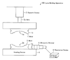
- FIG. 1 is a view illustrating an arrangement of a lens molding apparatus according to an embodiment of the present invention.
- FIG. 2 is a flowchart illustrating a procedure in the step of molding a lens according to the embodiment of the present invention.
- FIG. 3 is a view illustrating a state in which a resin material is supplied to a transfer surface of one mold.
- FIG. 4 is a view illustrating a state in which the resin material is cured by heating while a transfer surface of another mold is pressed against the resin material.
- FIG. 5 is a view illustrating a state in which ultrasonic vibration is applied from a side surface of the another mold.
- FIG. 6 is a view illustrating a state in which the transfer surface of the another mold is separated from the lens.
- FIG. 7 is a view illustrating a state in which ultrasonic vibration is applied from a side surface of the one mold.
- FIG. 8 is a view illustrating a state in which the lens is removed from the one mold.
- FIG. 9 is a table showing a relation between press force indicating an initial pressure at the time of mold release and mold release force required for the mold release; and (b) of FIG. 9 is a graph showing the relation.
- FIG. 10 is a modified example of the molds.
- FIG. 11 is a view illustrating an arrangement of a lens molding apparatus according to a modified example of the embodiment of the present invention.
- FIG. 12 is a view illustrating a mold of a conventional lens molding apparatus.
- FIG. 13 is a view illustrating a mold of another conventional lens molding apparatus.
- FIG. 1 is a view illustrating an arrangement of a lens molding apparatus (resin molding apparatus) 100 according to the present embodiment.
- the lens molding apparatus 100 is an apparatus for molding a lens from a resin material, and includes a mold 1 , a mold 2 , a support device 3 , a heating device 4 , an ultrasonic vibrator 5 , and a resonance device 6 .
- the mold 1 corresponds to a first mold in the claims and is supported by the support device 3 .
- the mold 2 corresponds to a second mold in the claims and is provided on the heating device 4 .
- the support device 3 has an extendable arm 3 a and is capable of moving the mold 1 up and down in FIG. 1 . Note that the support device 3 corresponds to moving means in the claims.
- the mold 1 has a transfer surface 1 a for transferring a predetermined lens shape to a resin material. At the center of the transfer surface 1 a , an aspherical depression is formed.
- the mold 2 has a transfer surface 2 a for transferring a predetermined lens shape to the resin material. At the center of this transfer surface 2 a , an aspherical depression is formed.
- the transfer surface 1 a and the transfer surface 2 a are opposed to each other.
- the heating device 4 corresponds to curing means in the claims and cures, by heating the mold 2 , the resin material supplied between the transfer surface 1 a and the transfer surface 2 a .
- the start/end of this heating may be controlled by a sequence program or the like, or alternatively controlled manually.
- the ultrasonic vibrator 5 corresponds to each of first vibration applying means and second vibration applying means in the claims, and produces ultrasonic vibration in accordance with signals supplied from the resonance device 6 .
- the ultrasonic vibrator 5 is attachable to a side surface 1 b of the mold 1 and a side surface 2 b of the mold 2 .
- FIG. 2 is a flowchart illustrating a procedure in the step of molding a lens according to the present embodiment.
- Step S 1 the resin material 7 is supplied between the transfer surface 1 a of the mold 1 and the transfer surface 2 a of the mold 2 .
- the resin material 7 is supplied onto the transfer surface 2 a of the mold 2 .
- the resin material 7 is a thermosetting resin that is cured by heating.
- Step S 2 the transfer surface 1 a of the mold 1 is pressed against the resin material 7 (Step S 2 ).
- the mold 2 is heated by the heating device 4 .
- the resin material 7 is cured (Step S 3 , the step of curing a resin material).
- Step S 4 heating is stopped and the resin material 7 is cooled. As a result, a lens 17 is formed.
- the ultrasonic vibrator 5 is attached to the side surface 1 b of the mold 1 .
- the resonance device 6 is caused to output a signal, so that the ultrasonic vibrator 5 is vibrated.
- the ultrasonic vibrator 5 applies ultrasonic vibration of, for example, 27 kHz from the side surface 1 b , and the mold 1 vibrates in a radial direction of the lens 17 (a shear direction, a surface direction of the transfer surface 1 a ) (Step S 5 , the first vibration applying step, the first step of applying vibration).
- This vibration causes elastic deformation of the mold 1 locally in the shear direction and produces a shear locally between the transfer surface 1 a and the lens 17 .
- Step S 6 the step of separating/releasing a mold.
- a gap is formed at least at a part between the transfer surface 1 a and the lens 17 . Accordingly, at the time of mold release, this gap stretches out all over a boundary between the transfer surface 1 a and the lens 17 . Therefore, it becomes possible to easily release the mold 1 from the lens 17 without putting a load on the lens 17 .
- the ultrasonic vibrator 5 is attached to the side surface 2 b of the mold 2 .
- the resonance device 6 is caused to output a signal, so that the ultrasonic vibrator 5 is vibrated.
- the ultrasonic vibrator 5 applies ultrasonic vibration of, for example, 27 kHz from the side surface 2 b and the mold 2 vibrates in a radial direction of the lens 17 (a shear direction, a surface direction of the transfer surface 2 a ) (Step S 7 , the second vibration applying step, the second step of applying vibration).
- This vibration causes elastic deformation of the mold 2 locally in the shear direction and produces a shear locally between the transfer surface 2 a and the lens 17 .
- a vacuum gap is formed between the lens 17 and the transfer surface 2 a . Consequently, adhesion between the transfer surface 2 a of the mold 2 and the lens 17 decreases. At the same time, at least a part of a surface of the lens 17 slightly peels off from the transfer surface 2 a . As a result, a gap is formed at least at a part between the transfer surface 2 a and the lens 17 .
- Step S 8 the step of removing a molded product.
- a gap is formed at least at a part between the transfer surface 2 a and the lens 17 . Accordingly, when the lens 17 is removed from the mold 2 , this gap stretches out all over a boundary between the transfer surface 2 a and the lens 17 . Therefore, it becomes possible to easily remove the lens 17 from the mold 2 without putting a load on the lens 17 .
- Step S 6 the step of separating/releasing a mold
- Step S 8 the step of removing a molded product
- a gap is formed locally between the lens 17 and the transfer surface 2 a by applying vibration in the radial direction of the lens 17 to the mold 2 .
- the mold 1 is first separated from the lens and then the lens is removed from the mold 2 .
- the present invention is not limited to this, but can be arranged such that the mold 2 is first separated from the lens and then the lens is removed from the mold 1 .
- the order of the first vibration applying step and the second vibration applying step can be reversed.
- ultrasonic vibration is first applied to a mold in contact with a lens surface which is on an opposite side to a lens surface in contact with another mold in which it is desired that the lens remain after the step of separating/releasing the lens from the mold. This makes it possible to control a position from which the lens is removed.
- FIG. 9 is a table showing a relation between press force indicating an initial pressure (force at which the transfer surface is pressed against the resin material) at the time of mold release and mold release force required for the mold release; and (b) of FIG. 9 is a graph showing this relation.
- a solid line shows release force in a method of the present embodiment according to which ultrasonic vibration at 27 kHz is applied to a mold prior to mold release and a dotted line shows release force in a common method according to which no ultrasonic vibration is applied.
- the release force could be reduced by approximately 70% by applying the ultrasonic vibration prior to the mold release.
- the ultrasonic vibration is applied from the side surface of the mold, only part of the mold vibrates. Therefore, as compared to a conventional arrangement where a whole transfer surface of a mold is vibrated, a load onto a lens can be reduced at the time when the vibration is applied.
- Step S 5 preferably, a gap is formed at least at a part between a non-optical surface 17 b of the lens 17 and the transfer surface 1 a in contact with the non-optical surface 17 b ; and no gap is formed between the optical surface 17 a of the lens 17 and the transfer surface 1 a .
- Step S 7 preferably, a gap is formed at least at a part between a non-optical surface 17 b of the lens 17 and the transfer surface 1 a in contact with the non-optical surface 17 b ; and no gap is formed between the optical surface 17 a of the lens 17 and the transfer surface 1 a .
- the optical surface means a surface involved in optical spot formation of the lens 17
- the non-optical surface means a surface that is not involved in the optical spot formation of the lens 17 .
- the non-optical surface is arranged as, for example, a flat flange section and formed on an outer periphery of the optical surface.
- Strength of the ultrasonic vibration is controlled so that a gap is formed only at the non-optical surface 17 b of the lens 17 . This makes it possible to further reduce the load onto the optical surface 17 a and further to suppress influence on performance of the lens 17 to the minimum.
- the lens molding apparatus 100 of the present embodiment can easily and highly accurately mold a lens having a complex shape. Further, this lens molding apparatus 100 also can easily mold a lens having a largely varying thickness and a large aspherical surface while widening a range of a resin material for the lens.
- molds 1 and 2 each employed for lens molding are molds for forming one lens in the present embodiment, but for example, molds for molding a plurality of lens provided in an array, such as molds 11 and 12 as illustrated in FIG. 10 , may be used.
- the ultrasonic vibration includes a component in a direction that is orthogonal to the transfer surface; however, a component in a radial direction of the lens (a surface direction of the transfer surface) is dominant in the ultrasonic vibration. Therefore, shear mold release force is mainly produced between the lens and the transfer surface.
- a velocity v of the ultrasonic vibration and an acceleration a of the ultrasonic vibration are respectively expressed as follows:
- phases of the velocity and the acceleration are shifted relative to each other by ⁇ /2. Accordingly, when the acceleration is maximum, the velocity becomes 0. Therefore, the closer the force P per unit area in the surface direction of the transfer surface is with respect to a minimum value of force necessary for mold release, the smaller the velocity of the lens after mold release becomes. Further, the larger the frequency f is, the more the velocity of the lens after the mold release can be suppressed with respect to the force in the surface direction of the transfer surface. Therefore, the closer the shear mold release force generated between the lens and the transfer surface is to the minimum value of the force necessary for mold release and the larger the frequency of the ultrasonic vibration is, the more the load on the lens can be suppressed.
- the vibration applied to the mold or a base plate prior to the step of separating/releasing the mold from a molded product and the step of removing a molded product is preferably ultrasonic vibration in a range of 20 kHz to 60 kHz though it varies depending on materials of the lens and the mold.
- FIG. 11 is a view illustrating an arrangement of a lens molding apparatus 200 according to the modified example of the present embodiment.
- the lens molding apparatus 200 is arranged by replacing the mold 2 in the lens molding apparatus 100 as illustrated in FIG. 1 to a base plate 9 .
- the base plate 9 is provided on a heating device 4 and an ultrasonic vibrator 5 is attachable to a side surface 9 a of the base plate 9 .
- the step of molding a lens in the lens molding apparatus 200 is substantially the same as that in the lens molding apparatus 100 . That is, a resin material is supplied between the base plate 9 and a transfer surface 1 a of a mold 1 . Then, in a state where the transfer surface 1 a is pressed against the resin material, the resin material is cured by heating so that the lens is formed. Next, ultrasonic vibration is applied by the ultrasonic vibrator 5 from a side surface 1 b of the mold 1 so that a gap is formed at least at a part between the transfer surface 1 a and the lens (the step of applying vibration to a mold). Subsequently, the transfer surface 1 a is separated from the lens.
- ultrasonic vibration is applied by the ultrasonic vibrator 5 from the side surface 9 a of the base plate 9 so that a gap is formed at least at a part between the base plate 9 and the lens (the step of applying vibration to a base plate). Thereafter, the lens is removed from the base plate 9 .
- a gap is formed locally between the lens and the transfer surface 1 a by applying vibration in a radial direction of the lens to the mold 1 ; and before the lens is removed from the base plate 9 , a gap is formed locally between the lens and the base plate 9 by applying vibration in a radial direction of the lens to the base plate 9 .
- These gaps serve as starting points from which the lens is separated from the transfer surfaces 1 a and the base plate 9 . This makes it possible to easily separate lens from the transfer surface 1 a and the substrate 9 .
- the order of the step of applying vibration to the mold and the step of applying vibration to the base plate may be reversed.
- first ultrasonic vibration is applied by the ultrasonic vibrator 5 from the side surface 9 a of the base plate 9 so that a gap is formed at least at a part between the base plate 9 and the lens.
- the base plate 9 is separated from the lens by moving the mold 1 upward. As a result, the lens is adhered to the transfer surface 1 a of the mold 1 .
- ultrasonic vibration is applied by the ultrasonic vibrator 5 from the side surface 1 b of the mold 1 so that a gap is formed at least at a part between the transfer surface 1 a and the lens. Thereafter, the lens is removed from the transfer surface 1 a.
- ultrasonic vibration is applied to the mold or the base plate.
- vibration applied to the mold or the base plate is not limited to ultrasonic vibration.
- the vibration may be acoustic wave vibration of less than 20 kHz.
- one ultrasonic vibrator is used to apply ultrasonic vibration to two molds, or to a mold and a base plate.
- separate ultrasonic vibrators may be used to apply ultrasonic vibration to two molds, respectively, or to a mold and a base plate, respectively.
- one member may be used for both first vibration applying means and second vibration applying means in the claims or separate members may be used respectively for first vibration applying means and second vibration applying means in the claims.
- the ultrasonic vibrator may be movable by use of a sliding mechanism.
- the resin molding apparatus further includes second vibration applying means that applies vibration from a side surface of the second mold so as to form a gap at least at a part between the second transfer surface and the resin molded product.
- vibration is applied by the second vibration applying means from a side surface of the second mold and thereby, a gap is formed at least at a part between the second transfer surface and the resin molded product.
- This gap serves as a starting point from which the resin molded product and the second transfer surface are separated from each other.
- the vibration is applied from the side surface of the second mold, only part of the second mold is vibrated.
- the vibration is indirectly applied to the resin molded product. Therefore, as compared to a conventional arrangement in which a whole transfer surface of a mold is vibrated, a load on the resin molded product can be reduced when the vibration is applied. Consequently, the resin molded product and the second mold can be easily separated from each other.
- the resin molding apparatus of the embodiment of the present invention further includes second vibration applying means that applies vibration from a side surface of the base plate so as to form a gap at least at a part between the base plate and the resin molded product.
- vibration is applied by the second vibration applying means from a side surface of the base plate and thereby, a gap is formed at least at a part between the base plate and the resin molded product.
- This gap serves as a starting point from which the resin molded product and the base plate are separated from each other.
- the vibration is applied from the side surface of the base plate, only part of the base plate is vibrated.
- the vibration is indirectly applied to the resin molded product. Therefore, as compared to a conventional arrangement in which a whole transfer surface of a mold is vibrated, a load on the resin molded product can be reduced when the vibration is applied. Consequently, it is possible to easily remove the resin molded product from the base plate.
- the first vibration applying means and the second vibration applying means are provided by use of one member.
- the vibration is ultrasonic vibration.
- the resin molded product is one or more lenses.
- mold release can be performed without putting a load on the resin material. Therefore, the embodiment of the present invention is particularly suitable for molding a lens having a complex shape.
- the lens has an optical surface and a non-optical surface formed on an outer periphery of the optical surface; and the gap is formed at least at a part between the non-optical surface and a surface in contact with the non-optical surface but no gap is formed between the optical surface and a surface in contact with the optical surface.
- a gap is formed only at the non-optical surface of the resin molded product. Accordingly, it is possible to further reduce a load on the optical surface at the time when the mold is released or the resin molded product is removed. This makes it possible to suppress influence on performance of the resin molded product to the minimum.
- the resin molding method of the embodiment of the present invention further includes the step of applying vibration from a side surface of the second mold so as to form a gap at least at a part between the second transfer surface and the resin molded product, the vibration being applied between the step of separating the first transfer surface from the resin molded product and the step of removing the resin molded product.
- vibration is applied from a side surface of the second mold and thereby, a gap is formed at least at a part between the second transfer surface and the resin molded product.
- This gap serves as a starting point from which the resin molded product and the second transfer surface are separated from each other in the step of removing the resin molded product.
- the vibration is applied from the side surface of the second mold, only part of the second mold is vibrated.
- the vibration is indirectly applied to the resin molded product. Therefore, as compared to a conventional arrangement in which a whole transfer surface of a mold is vibrated, a load on the resin molded product can be reduced when the vibration is applied. Consequently, the resin molded product and the second mold can be easily separated from each other.
- the resin molding method of the embodiment of the present invention further includes the step of applying vibration to the base plate by applying vibration from a side surface of the base plate so as to form a gap at least at a part between the base plate and the resin molded product, the vibration being applied between the step of separating the transfer surface from the resin molded product and the step of removing the resin molded product.
- vibration is applied from the side surface of the base plate, and thereby, a gap is formed at least at a part between the base plate and the resin molded product.
- This gap becomes a starting point from which the resin molded product and the base plate are separated from each other in the step of removing the resin molded product.
- the vibration is applied from the side surface of the base plate, only part of the base plate is vibrated. As described above, the vibration is indirectly applied to the resin molded product. Therefore, a load on the resin molded product can be reduced when the vibration is applied. Consequently, it is possible to easily remove the resin molded product from the base plate.
- the resin molding method of the embodiment of the present invention further includes the step of applying vibration to the mold by applying vibration from a side surface of the mold so as to form a gap at least at a part between the transfer surface and the resin molded product, the vibration being applied between the step of separating the base plate from the resin molded product and the step of removing the resin molded product.
- vibration is applied from a side surface of the mold and thereby, a gap is formed at least at a part between the transfer surface and the resin molded product.
- This gap serves as a starting point from which the resin molded product and the transfer surface are separated from each other in the step of removing the resin molded product.
- the vibration is applied from the side surface of the mold, only part of the mold is vibrated.
- the vibration is indirectly applied to the resin molded product. Therefore, as compared to a conventional arrangement in which a whole transfer surface of a mold is vibrated, a load on the resin molded product can be reduced when the vibration is applied. Consequently, it is possible to easily remove the resin molded product from the base plate.
- the vibration is ultrasonic vibration.
- the resin molded product is one or more lenses.
- the embodiment of the present invention is particularly suitable for molding a lens having a complex shape.
- the lens has an optical surface and a non-optical surface formed on an outer periphery of the optical surface; and the gap is formed at least at a part between the non-optical surface and a surface in contact with the non-optical surface but no gap is formed between the optical surface and a surface in contact with the optical surface.
- a gap is formed only at the non-optical surface of the resin molded product. Accordingly, it is possible to further reduce a load on the optical surface in the step of separating the first transfer surface, the transfer surface or the base plate from the resin molded product or the step of removing the resin molded product. This makes it possible to suppress influence on performance of the resin molded product to the minimum.
- the present invention is applicable not only to a lens molding apparatus but also to an apparatus for molding any resin molded product other than lenses.
Landscapes
- Engineering & Computer Science (AREA)
- Mechanical Engineering (AREA)
- Manufacturing & Machinery (AREA)
- Health & Medical Sciences (AREA)
- Ophthalmology & Optometry (AREA)
- Moulds For Moulding Plastics Or The Like (AREA)
- Casting Or Compression Moulding Of Plastics Or The Like (AREA)
- Injection Moulding Of Plastics Or The Like (AREA)
Abstract
Description
- Japanese Patent Application Publication, Tokukaihei, No. 4-361010 A (Publication Date: Dec. 14, 1992)
[Patent Literature 2] - Japanese Patent Application Publication, Tokukai, No. 2004-74445 (Publication Date: Mar. 11, 2004)
[Patent Literature 3] - Japanese Patent Application Publication, Tokukai, No. 2010-266664 (Nov. 25, 2010)
z=A sin(2πft) [Expression 1]
where: A is an amplitude of the ultrasonic vibration; and f is a frequency of the ultrasonic vibration. Moreover, a velocity v of the ultrasonic vibration and an acceleration a of the ultrasonic vibration are respectively expressed as follows:
F=Ma=Shρ·4π2 f 2 A [Expression 3]
where: M is a mass of the lens; S is an area of the lens; h is a thickness of the lens; and ρ is a density of the lens. Further, when P is a maximum value of force acting on a unit area of the lens,
P=F/S=4π2 f 2 Ahρ [Expression 4]
v=2πfA [Expression 5]
- 1 mold
- 1 a transfer surface
- 1 b side surface
- 2 mold
- 2 a transfer surface
- 2 b side surface
- 3 support device
- 3 a arm
- 4 heating device
- 5 ultrasonic vibrator
- 6 resonance device
- 7 resin material
- 8 dispenser
- 9 base plate
- 9 a side surface
- 11 mold
- 12 mold
- 17 lens
- 17 a optical surface
- 17 b non-optical surface
- 100 lens molding apparatus
- 200 lens molding apparatus
Claims (1)
Applications Claiming Priority (3)
| Application Number | Priority Date | Filing Date | Title |
|---|---|---|---|
| JP2011-128558 | 2011-06-08 | ||
| JP2011128558A JP5154674B2 (en) | 2011-06-08 | 2011-06-08 | Resin molding apparatus and resin molding method |
| PCT/JP2012/064713 WO2012169599A1 (en) | 2011-06-08 | 2012-06-07 | Resin molding apparatus and resin molding method |
Publications (2)
| Publication Number | Publication Date |
|---|---|
| US20140103552A1 US20140103552A1 (en) | 2014-04-17 |
| US9643345B2 true US9643345B2 (en) | 2017-05-09 |
Family
ID=47296154
Family Applications (1)
| Application Number | Title | Priority Date | Filing Date |
|---|---|---|---|
| US14/123,759 Active 2032-07-21 US9643345B2 (en) | 2011-06-08 | 2012-06-07 | Resin molding apparatus and resin molding method |
Country Status (5)
| Country | Link |
|---|---|
| US (1) | US9643345B2 (en) |
| JP (1) | JP5154674B2 (en) |
| CN (1) | CN103561928B (en) |
| TW (1) | TWI510348B (en) |
| WO (1) | WO2012169599A1 (en) |
Cited By (2)
| Publication number | Priority date | Publication date | Assignee | Title |
|---|---|---|---|---|
| US11179901B2 (en) * | 2011-11-18 | 2021-11-23 | Eric Hurdle | Process and apparatus for molding composite articles |
| US20220266554A1 (en) * | 2016-12-16 | 2022-08-25 | Alcon Inc. | Method for producing contact lenses |
Families Citing this family (12)
| Publication number | Priority date | Publication date | Assignee | Title |
|---|---|---|---|---|
| JP2014217951A (en) * | 2013-05-01 | 2014-11-20 | 株式会社リコー | Method and device for manufacturing flat-type part, and mold |
| DE102014104007A1 (en) * | 2014-03-24 | 2015-09-24 | Deutsches Zentrum für Luft- und Raumfahrt e.V. | Device and method for demolding a plastic component |
| US9938034B2 (en) | 2014-12-19 | 2018-04-10 | Coopervision International Holding Company, Lp | Method and apparatus relating to manufacture of molds for forming contact lenses |
| US9937640B2 (en) | 2014-12-19 | 2018-04-10 | Coopervision International Holding Company, Lp | Apparatus and method for closure of ophthalmic lens molds |
| US9764501B2 (en) | 2014-12-19 | 2017-09-19 | Coopervision International Holding Company, Lp | Contact lens mold parts, contact lens mold assemblies, and methods of making contact lenses |
| US10029402B2 (en) | 2014-12-19 | 2018-07-24 | Coopervision International Holding Company, Lp | Method and apparatus for manufacturing contact lenses |
| GB2533406B (en) * | 2014-12-19 | 2018-10-31 | Coopervision Int Holding Co Lp | Methods and apparatus for manufacture of ophthalmic lenses |
| US10137612B2 (en) | 2014-12-19 | 2018-11-27 | Coopervision International Holding Company, Lp | Methods and apparatus for manufacture of ophthalmic lenses |
| KR102290487B1 (en) * | 2020-02-07 | 2021-08-17 | (주)대호테크 | Lens and mold transfer system |
| KR102505223B1 (en) * | 2021-04-23 | 2023-03-02 | 한국광기술원 | Apparatus and Method for Producing Wafer Lens with improved lens releasability |
| NL2030237B1 (en) * | 2021-12-22 | 2023-06-29 | Amo Groningen Bv | Method and an assembly for removing an intraocular lens from an injection molded mold half |
| WO2025111003A1 (en) * | 2023-11-22 | 2025-05-30 | Canon Virginia, Inc. | Method for producing organic polymers, and molded bodies, and molds for molding of the organic polymers |
Citations (5)
| Publication number | Priority date | Publication date | Assignee | Title |
|---|---|---|---|---|
| JPS61283509A (en) | 1985-06-10 | 1986-12-13 | Shimada Phys & Chem Ind Co Ltd | Separating of plastic lens from matrix |
| JPH04361010A (en) | 1991-06-06 | 1992-12-14 | Olympus Optical Co Ltd | Method and device for molding compound lens |
| JP2004074445A (en) | 2002-08-12 | 2004-03-11 | Citizen Electronics Co Ltd | Method for demolding resin molded product |
| JP2007320037A (en) | 2006-05-30 | 2007-12-13 | Matsushita Electric Ind Co Ltd | Mold and mold release method |
| JP2010266664A (en) | 2009-05-14 | 2010-11-25 | Fujifilm Corp | Wafer level lens array manufacturing method, wafer level lens array, lens module, and imaging unit |
Family Cites Families (7)
| Publication number | Priority date | Publication date | Assignee | Title |
|---|---|---|---|---|
| JPS6076319A (en) * | 1983-10-01 | 1985-04-30 | Canon Inc | Mold release method using ultrasonic waves |
| FR2604063A1 (en) * | 1986-09-22 | 1988-03-25 | Mecasonic Sa | Device for demoulding industrial food products |
| JPH0684025B2 (en) * | 1988-09-19 | 1994-10-26 | 松下電工株式会社 | Mold release method |
| JPH05326597A (en) * | 1992-05-20 | 1993-12-10 | Toowa Kk | Resin molding equipment for electronic parts and mold release method |
| JP3711728B2 (en) * | 1998-01-27 | 2005-11-02 | 富士ゼロックス株式会社 | Method for casting a microstructure and casting mold |
| TW200609099A (en) * | 2004-09-10 | 2006-03-16 | Asahi Rubber Inc | Method for manufacturing resin lens for semiconductor optical element |
| TWI283631B (en) * | 2005-10-25 | 2007-07-11 | Ind Tech Res Inst | Method and device for demolding |
-
2011
- 2011-06-08 JP JP2011128558A patent/JP5154674B2/en not_active Expired - Fee Related
-
2012
- 2012-06-07 WO PCT/JP2012/064713 patent/WO2012169599A1/en not_active Ceased
- 2012-06-07 CN CN201280027162.3A patent/CN103561928B/en active Active
- 2012-06-07 US US14/123,759 patent/US9643345B2/en active Active
- 2012-06-07 TW TW101120547A patent/TWI510348B/en not_active IP Right Cessation
Patent Citations (5)
| Publication number | Priority date | Publication date | Assignee | Title |
|---|---|---|---|---|
| JPS61283509A (en) | 1985-06-10 | 1986-12-13 | Shimada Phys & Chem Ind Co Ltd | Separating of plastic lens from matrix |
| JPH04361010A (en) | 1991-06-06 | 1992-12-14 | Olympus Optical Co Ltd | Method and device for molding compound lens |
| JP2004074445A (en) | 2002-08-12 | 2004-03-11 | Citizen Electronics Co Ltd | Method for demolding resin molded product |
| JP2007320037A (en) | 2006-05-30 | 2007-12-13 | Matsushita Electric Ind Co Ltd | Mold and mold release method |
| JP2010266664A (en) | 2009-05-14 | 2010-11-25 | Fujifilm Corp | Wafer level lens array manufacturing method, wafer level lens array, lens module, and imaging unit |
Non-Patent Citations (3)
| Title |
|---|
| International Search Report for PCT/JP2012/064713, mailed Aug. 21, 2012. |
| Machine Translation of JP 2007-320037. * |
| Written Opinion for PCT/JP2012/064713, mailed Aug. 21, 2012. |
Cited By (3)
| Publication number | Priority date | Publication date | Assignee | Title |
|---|---|---|---|---|
| US11179901B2 (en) * | 2011-11-18 | 2021-11-23 | Eric Hurdle | Process and apparatus for molding composite articles |
| US20220266554A1 (en) * | 2016-12-16 | 2022-08-25 | Alcon Inc. | Method for producing contact lenses |
| US12521948B2 (en) * | 2016-12-16 | 2026-01-13 | Alcon Inc. | Method for producing contact lenses |
Also Published As
| Publication number | Publication date |
|---|---|
| TWI510348B (en) | 2015-12-01 |
| CN103561928A (en) | 2014-02-05 |
| WO2012169599A1 (en) | 2012-12-13 |
| CN103561928B (en) | 2016-10-19 |
| JP5154674B2 (en) | 2013-02-27 |
| US20140103552A1 (en) | 2014-04-17 |
| JP2012254559A (en) | 2012-12-27 |
| TW201311422A (en) | 2013-03-16 |
Similar Documents
| Publication | Publication Date | Title |
|---|---|---|
| US9643345B2 (en) | Resin molding apparatus and resin molding method | |
| JP6817292B2 (en) | Laminated modeling equipment | |
| US8951886B2 (en) | Method for separating a layer system comprising a wafer by precisely maintaining the position of the separating front | |
| CN103635835B (en) | Optical element manufacturing method and surface processing device | |
| JPH04361010A (en) | Method and device for molding compound lens | |
| US9370879B2 (en) | Resin molding apparatus and resin molding method | |
| JP2014004826A (en) | Pattern forming method and mold release device | |
| JP5913244B2 (en) | Mold release device | |
| CN209879251U (en) | A Nanoimprinting Device Based on Non-resonant Assist | |
| JPH0866972A (en) | Manufacture of composite type optic | |
| JP7240479B1 (en) | Tape application device, resin molding system, tape application method, and method for manufacturing resin molded product | |
| JP2003154573A (en) | Molding apparatus for emboss processing and emboss processing molding method | |
| US20160086839A1 (en) | Method For The Production Of A Wafer With A Carrier Unit | |
| CN112018967A (en) | Method for manufacturing vibration damping member | |
| CN110154293A (en) | Manufacturing method of gel-like member | |
| JP2002128530A (en) | Optical element molding method | |
| CN113134967B (en) | Thin film structure for photocuring 3D printing and its manufacturing method | |
| JP2014004827A (en) | Pattern forming method and mold release device | |
| JP2006248804A (en) | Glass molding apparatus | |
| JP2019214410A (en) | Holding plate for electric part | |
| HK1165092A (en) | Method for separating a layer system comprising a wafer | |
| HK1165092B (en) | Method for separating a layer system comprising a wafer | |
| CN116080063A (en) | Quick 3D printing equipment |
Legal Events
| Date | Code | Title | Description |
|---|---|---|---|
| AS | Assignment |
Owner name: SHARP KABUSHIKI KAISHA, JAPAN Free format text: ASSIGNMENT OF ASSIGNORS INTEREST;ASSIGNORS:NAKAHASHI, TAKAHIRO;HANATO, HIROYUKI;REEL/FRAME:031709/0560 Effective date: 20131106 |
|
| STCF | Information on status: patent grant |
Free format text: PATENTED CASE |
|
| MAFP | Maintenance fee payment |
Free format text: PAYMENT OF MAINTENANCE FEE, 4TH YEAR, LARGE ENTITY (ORIGINAL EVENT CODE: M1551); ENTITY STATUS OF PATENT OWNER: LARGE ENTITY Year of fee payment: 4 |
|
| MAFP | Maintenance fee payment |
Free format text: PAYMENT OF MAINTENANCE FEE, 8TH YEAR, LARGE ENTITY (ORIGINAL EVENT CODE: M1552); ENTITY STATUS OF PATENT OWNER: LARGE ENTITY Year of fee payment: 8 |