US9642093B2 - Method and system for operating stations in a cooperative station network - Google Patents
Method and system for operating stations in a cooperative station network Download PDFInfo
- Publication number
- US9642093B2 US9642093B2 US14/430,234 US201314430234A US9642093B2 US 9642093 B2 US9642093 B2 US 9642093B2 US 201314430234 A US201314430234 A US 201314430234A US 9642093 B2 US9642093 B2 US 9642093B2
- Authority
- US
- United States
- Prior art keywords
- station
- stations
- carrier sense
- range
- signals
- Prior art date
- Legal status (The legal status is an assumption and is not a legal conclusion. Google has not performed a legal analysis and makes no representation as to the accuracy of the status listed.)
- Active
Links
Images


Classifications
-
- H—ELECTRICITY
- H04—ELECTRIC COMMUNICATION TECHNIQUE
- H04W—WIRELESS COMMUNICATION NETWORKS
- H04W52/00—Power management, e.g. TPC [Transmission Power Control], power saving or power classes
- H04W52/04—TPC
- H04W52/18—TPC being performed according to specific parameters
- H04W52/24—TPC being performed according to specific parameters using SIR [Signal to Interference Ratio] or other wireless path parameters
- H04W52/242—TPC being performed according to specific parameters using SIR [Signal to Interference Ratio] or other wireless path parameters taking into account path loss
-
- H—ELECTRICITY
- H04—ELECTRIC COMMUNICATION TECHNIQUE
- H04L—TRANSMISSION OF DIGITAL INFORMATION, e.g. TELEGRAPHIC COMMUNICATION
- H04L67/00—Network arrangements or protocols for supporting network services or applications
- H04L67/01—Protocols
- H04L67/12—Protocols specially adapted for proprietary or special-purpose networking environments, e.g. medical networks, sensor networks, networks in vehicles or remote metering networks
-
- H—ELECTRICITY
- H04—ELECTRIC COMMUNICATION TECHNIQUE
- H04W—WIRELESS COMMUNICATION NETWORKS
- H04W52/00—Power management, e.g. TPC [Transmission Power Control], power saving or power classes
- H04W52/04—TPC
- H04W52/18—TPC being performed according to specific parameters
- H04W52/24—TPC being performed according to specific parameters using SIR [Signal to Interference Ratio] or other wireless path parameters
- H04W52/243—TPC being performed according to specific parameters using SIR [Signal to Interference Ratio] or other wireless path parameters taking into account interferences
-
- H—ELECTRICITY
- H04—ELECTRIC COMMUNICATION TECHNIQUE
- H04W—WIRELESS COMMUNICATION NETWORKS
- H04W52/00—Power management, e.g. TPC [Transmission Power Control], power saving or power classes
- H04W52/04—TPC
- H04W52/18—TPC being performed according to specific parameters
- H04W52/24—TPC being performed according to specific parameters using SIR [Signal to Interference Ratio] or other wireless path parameters
- H04W52/245—TPC being performed according to specific parameters using SIR [Signal to Interference Ratio] or other wireless path parameters taking into account received signal strength
-
- H—ELECTRICITY
- H04—ELECTRIC COMMUNICATION TECHNIQUE
- H04W—WIRELESS COMMUNICATION NETWORKS
- H04W52/00—Power management, e.g. TPC [Transmission Power Control], power saving or power classes
- H04W52/04—TPC
- H04W52/18—TPC being performed according to specific parameters
- H04W52/24—TPC being performed according to specific parameters using SIR [Signal to Interference Ratio] or other wireless path parameters
- H04W52/246—TPC being performed according to specific parameters using SIR [Signal to Interference Ratio] or other wireless path parameters where the output power of a terminal is based on a path parameter calculated in said terminal
-
- H—ELECTRICITY
- H04—ELECTRIC COMMUNICATION TECHNIQUE
- H04W—WIRELESS COMMUNICATION NETWORKS
- H04W84/00—Network topologies
- H04W84/18—Self-organising networks, e.g. ad-hoc networks or sensor networks
-
- H—ELECTRICITY
- H04—ELECTRIC COMMUNICATION TECHNIQUE
- H04W—WIRELESS COMMUNICATION NETWORKS
- H04W88/00—Devices specially adapted for wireless communication networks, e.g. terminals, base stations or access point devices
- H04W88/08—Access point devices
Definitions
- the present invention relates to a method for operating stations in a cooperative station network, preferably a vehicular ad hoc network, wherein the stations transmit signals and receive signals from other stations.
- the present invention also relates to a system for operating stations in a cooperative station network, preferably a vehicular ad hoc network, wherein stations transmit signals and receive signals from other stations.
- Cooperative vehicular networks or systems are used to increase road safety and traffic efficiency.
- Such cooperative vehicular networks may be based on wireless communication based on IEEE 802.11 wireless LAN technology among vehicles and between vehicles and a roadside infrastructure, for example roadside infrastructure nodes according to IEEE 208.11p and/or its European variant according to ETSI EN 302 663 “Intelligent Transport Systems” (ITS).
- the stations are vehicles, i. e. highly dynamic nodes with challenging propagation conditions.
- a dedicated spectrum in the 5 GHz range was allocated.
- the communication channels can easily be saturated. This saturation leads to an unreliable communication between the vehicles and therefore in an inefficient operation of the cooperative vehicular network.
- the time for accessing a communication channel is significantly increased and the probability of packet reception is decreased at all distances or in other words packet loss is increased.
- the transmit power respectively output power of stations/nodes, here vehicles, in the cooperative vehicular network may be adjusted according to the actual load on the communication channels in the cooperative vehicular network. By decreasing the transmit power of a sent packet, this also reduces the spatial coverage and hence the load at a particular location in the communication range of the vehicle sending out the packet.
- Further conventional options to control congestion on the wireless communication channel include for example adjusting the packet generation rate, the carrier sense threshold or a combination of both of them.
- D-FPAV is a transmit power control algorithm achieving congestion control under so-called fairness constraints.
- the term “Fairness” may for example be defined as in M. Torrent-Moreno, P. Santi, and H. Hartenstein, “Fair sharing of bandwidth in VANETs,” in Proceedings of the 2nd ACM international workshop on Vehicular ad hoc networks (VANET), 2005, pp. 49-58.
- Congestion control in the wireless communication channel is according to D-FPAV achieved by exchanging of neighbour position information piggybacked in extended beacon signals from the vehicles.
- the added control information causes overhead scaling with the number of neighbour nodes/vehicles.
- Another alternative to reduce the overhead is to estimate the node density around every node and exchange a constant-size histogram of the node density in road segments as proposed in Mittag, J.; Schmidt-Eisenlohr, F.; Killat, M.; Harri, J.; Hartenstein, H., “Analysis and Design of Effective and Low-Overhead Transmission Power Control for VANETs”, Proceedings of the fifth ACM VANET 2008 (DVDE/SPAV).
- CCA clear channel assessment
- These conventional congestion control methods may be classified into proactive, reactive and hybrid methods.
- Reactive methods use information about the general congestion status based on local information or remote information transmitted from other nodes.
- Proactive methods estimate the transmission parameters that do not lead to congestion.
- Hybrid methods combine proactive and reactive methods.
- the present invention provides a method for operating a plurality of stations in a cooperative station network, wherein each of the stations transmits signals and receives signals from other stations.
- a path loss is determined between at least two of the stations.
- a carrier sense range for signals of a first station of the stations is determined based on the path loss and received power of signals from the other stations.
- a load on a dedicated signal exchange channel is determined based on the determined carrier sense range.
- a maximum output power for the first station is determined based on the determined load. The first station is operated by adjusting the output power of the first station to be, at least on average below the determined maximum output power for the first station.
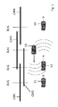
- FIG. 1 shows a scenario for a method according to an embodiment of the present invention.
- FIG. 2 shows a method according to an embodiment of the present invention.
- the inventors have recognized that one of the problems of proactive and hybrid methods is to correctly estimate the load in the wireless communication channels. Another problem recognized and addressed by the inventors is how to determine a mapping from transmit power levels of individual stations to a carrier sense range with a low protocol overhead.
- the present invention provides a method and a system for operating stations in a cooperative station network, which reduces protocol overhead.
- the present invention also provides a method and a system for operating stations in a cooperative station network which enable a more precise determination of the channel load.
- the present invention further provides a method and a system for operating stations in a cooperative station network based on locally collected information.
- the present invention even further provides a method and a system for operating stations in a cooperative station network enabling a network load in general below a pre-given threshold under highly changing conditions of stations.
- the present invention even further provides a method and a system for operating stations in a cooperative station network enabling an easy implementation with little additional complexity.
- a method is defined to operate stations in a cooperative station network, preferably a vehicular ad hoc network comprising stations which transmit signals and receive signals from other stations.
- a system for operating stations in a cooperative station network is defined, preferably the vehicular ad hoc network, comprising stations, wherein the stations transmit signals and receive signals from other stations, preferably for performing with the method according to the embodiments of the present invention.
- the system includes:
- a pass loss device operable to determine a path loss between at least two stations
- a range device operable to determine a carrier sense range for signals of a station based on the path loss and received power of signals from other stations
- a load device operable to determine a load on a dedicated signal exchange channel based on the carrier sense range
- a power determining device operable to determine a maximum output power for a station based on the determined load
- An operating device operable to adjust the output power of the station, so that the output power is below the maximum output power for this station, at least on average.
- the method and the system are independent of a centralized coordinating infrastructure.
- the network load can be maintained below a pre-defined threshold and protocol overhead in signals between the station is minimized.
- relevant parameters for determining the output power are derived from locally collected information, in particular from signals from other stations.
- a one slope path loss model is used for determining the path loss, preferably based on wavelength of the signals, distance to other stations and/or a path loss exponent.
- One of the advantages with a one slope path loss model is that the path loss can be determined with sufficient accuracy while at the same time providing an easy and fast determination.
- a fading intensity is determined for determining the path loss and preferably modeled by a shape parameter.
- determining the fading intensity a more realistic, i.e. more precise value for the path loss can be determined.
- the fading intensity is modeled by a shape parameter an easy and fast calculation of the fading intensity is possible.
- the receive power is determined based on a gamma-distribution with the shape parameter and/or the receiving station sensitivity.
- the received power at a point at a certain distance from a transmitter can be modeled being above the sensitivity S of the receiver.
- a probability p may be expressed in terms of the gamma-function:
- ⁇ (m, x) is the upper incomplete gamma-function
- S is the sensitivity of the receiver
- A is 4 ⁇ / ⁇ 2 with ⁇ being the wavelength of the carrier, ⁇ being the path loss exponent and m being the shape parameter.
- neighbour station information preferably signal sending rate, signal size and/or station density is used. This enables a fast and reliable determination of the channel load with easy-to-access respectively easy-to-determine parameters such as sending packet rate, data rate, etc.
- a Nakagami-m model is used for determining the received power.
- a precise determination of the attenuation of wireless signals traversing multiple paths is enabled.
- the station density is based, preferably estimated, on the number of neighbour stations in the carrier sense range.
- This enables a realistic, i.e. with sufficient accuracy, determination of the station density in a fast and efficient way.
- the average number of neighbours discovered ⁇ circumflex over (N) ⁇ is divided by the average transmission range/carrier sense range r CS of signals so that the vehicle density is ⁇ circumflex over (N) ⁇ /2r CS .
- This enables in particular in high channel load conditions a more reliable determination of the number of neighbours and therefore the station density:
- the interference range r I can then be used to correct the station density ⁇ in both cases:
- a margin is added to the determined maximum output power.
- the channel load and therefore the determined output power may also vary over an average value when for example parameter estimates are updated in certain time intervals.
- a safety margin is added to ensure that the channel load and therefore that the output power of stations based on it is below the determined maximum output power.
- a neighbour station table is created and updated comprising collected information included in signals form other neighbour stations. This provides and easy access to information collected from neighbour stations which may be kept and updated every time a new signal is received.
- entries of a neighbour station table are removed after a pre-given time-period.
- This enables on the one hand a very flexible way to adapt the neighbour station table: For example if the pre-given time-period, the table update time, is too high, then stations may overestimate the number of neighbours so the time period has to be adapted according to changing conditions, for example with respect to station density.
- this station density is determined based on a measured channel business time and on data rate, signal rate and signal size of received signals from other stations.
- the number of neighbour stations is not overestimated if no other kind of traffic is present.
- the interference range is used to correct the station density when interferences and/or a channel load are above a certain threshold. This enables to initiate interference correction for use only under high load conditions. When for example the channel load, for example represented by the channel business time falls below a given threshold the interference correction is deactivated. Therefore, a more complicated determination of the station density is only used in cases where interferences or channel load avoid a realistic respectively precise determination of the station density, thus avoiding unnecessary and complicated calculation when not needed.
- the carrier sense range for determining the station density is estimated by the average transmit power used by neighbour stations.
- the parameter of the average transmit power used by neighbour stations can be easily measured respectively determined, so that the station density via the carrier sense range can be determined in a fast and efficient way.
- the signal is provided in form of a beacon signal.
- Beacon signals are signals which are regularly respectively periodically sent and can therefore be used for vehicle safety applications in vehicular networks.
- FIG. 1 different vehicles V 1 , V 2 , V 3 , V 4 are shown, wherein the vehicles V 1 , V 2 and V 4 travel form left to right and vehicle V 3 travels from right to left. Further, the beacon load BL is shown for each vehicle V 1 , V 2 , V 3 and V 4 .
- the carrier sense ranges CSR 1 , CSR 2 , CSR 3 and CSR 4 corresponding to the vehicles V 1 , V 2 , V 3 and V 4 are shown with horizontal lines.
- FIG. 2 shows a method according to an embodiment of the present invention.
- FIG. 2 main steps of the method according to an embodiment of the present invention are shown in a flow chart.
- the carrier sense range r_cs is determined based on path loss with a one slope path loss model with wavelength ⁇ , distance y and path loss exponent ⁇ and based on the receive power P_r, determined by a ⁇ -distribution with shape parameter m and receiver- or station-sensitivity S.
- Step S 1 ′ a parameter estimation for the path loss exponent ⁇ and the shape parameter m for modeling fading intensity is estimated and neighbour information for the path loss determination like distance y, transmit power P_t and receive power P_r are determined.
- a second step S 2 the channel load L, preferably with interference correction of the station density p is determined based on the carrier sense range r_cs of step S 1 .
- a parameter estimation for the node- or station-density ⁇ is performed and further, neighbour information, preferably signal rate and signal size, here beacon rate B_r and beacon size B_s are used.
- the maximum power P* that keeps the channel load under the maximum beacon load is determined. If necessary the output power of the corresponding station is then adjusted accordingly, so that the output power is below the maximum output power.
- a vehicular network is considered in one dimension having a traffic flow with an average density of vehicles ⁇ per meter. Further, it may be assumed that vehicles transmit with a constant power p over a fading channel with path loss attenuation. It may be assumed that fading is a Fast-Term- or Rayleigh-fading. Based on these assumptions the power of a signal received at a location y from a transmitter at a position x is then pF/l(lx ⁇ yl), where l(x) is a path loss attenuation model and F is an exponential random variable with mean 1.
- the received power follows a gamma-distribution according the more general Nakagami-m model with parameters m and ⁇ being a shape and a scale parameter.
- the virtual power is then a random variable F, whose probability distribution function is
- the fading intensity is given by the parameter m, wherein a lower value applies more severe fading conditions. When the parameter m has the value 1, this corresponds to Rayleigh fading.
- Carrier sense range corresponds to transmission range as that one where the signal from a receiver can be detected.
- the Signal to Interference-plus-Noise Ratio SINR has to be greater than a certain value T, which results in a smaller effective transmission range.
- T the Signal to Interference-plus-Noise Ratio SINR
- a channel business time CBT may be defined as the fraction of time that a receiver considers the channel occupied in a time interval.
- the channel business time CBT is commonly measured and made available by the stations.
- the maximum power to be used to keep the average load under a given maximum beacon load L m can be determined as follows:
- Every vehicle may compute the maximum power p* and may adjust its output power accordingly so that the general load is under the maximum beacon load L m , according to vehicle density ⁇ and to general conditions, summarized by respectively represented by the path loss exponent ⁇ and the shape parameter m. Since these values are known a priori and may change over time, vehicles may periodically estimate them from the information they have available.
- load which is generated by surrounding neighbours may be measured, either using the station- or node-density, here the vehicle density or the channel distance time and the transmit power respectively output power is increased or decreased according the maximum power p* using the estimated channel parameters.
- the estimation of channel parameters maybe performed as follows and in advance the following assumptions are made: Since the transmission range and station density/vehicle density/node density are independent random variables, the average channel load is given by the multiplication of their average values.
- the beaconing rate is not independent of other variables so three rates maybe distinguished: The nominal beaconing rate b r , the transmitted beaconing rate b′ r and the effective beaconing rate b r . The first one is the beaconing offered load, whereas b′ r is the beacon rate actually transmitted by the vehicle after medium access control operation contributing to channel load. At high load conditions the medium access control saturates and beacons are discarded. Therefore the beacon rate b′ r depends on the vehicle density.
- transmit power control reduces the number of neighbour vehicles before their medium access control enters saturation. Therefore it is assumed that b r ⁇ b′ r and is independent of vehicle density and transmit power.
- the effective beaconing rate b r is the rate of beacons correctly received from a neighbour vehicle. Once transmit power control is enabled, the effective beaconing rate is determined by fading and hidden node collisions. The fraction of packet lost due to fading is accounted for with the average carrier sense radius r CS and so the nominal beaconing rate is the correct rate to be used in equation above for the average channel load L.
- the estimated communication range may be estimated under interference which is described in the following.
- the vehicle will consider the channel busy either if the vehicle may decode packets or they are corrupted by a hidden-node collisions or interference. Since however part of the interfered transmissions overlap, the measured channel business time CBT is lower than the corresponding average channel load determined with the corresponding equation above. For controlling the congestion in the vehicle or network this provides sufficient accuracy since the channel load overestimation results in lower transmit power p* which represents a worst case approach.
- the estimated communication range under interference can be used to estimate the fraction of packets lost by hidden-node collisions and correct the value of the average channel load L.
- beaconing rate b r and beacon size b s is constant. It is further assumed that the transmitted power is not converged to a single value for every vehicle, since in reality vehicle signal output power can only take discrete values and vehicles may use or determine different values of the transmit power.
- the transmit power is expected to vary over an average value as the environment estimates for parameters are updated. It is assumed and expected that the channel load oscillates around the determined maximum beacon load value, so that a safety margin may be assigned.
- Vehicles may estimate their value from the information carried by beacons collected from other vehicles and their own low-level measurements. That is, for the path loss exponent a single slope model is assumed and vehicles may collect a sample of it from every beacon as follows:
- ⁇ i ln ⁇ ( P t , i ⁇ ⁇ ⁇ P r , t ) ln ⁇ ( ⁇ x )
- P t,i and the vehicle position are part of the information usually carried by beacons, whereas P r,i can be provided by conventional network hardware.
- the estimate for the path loss exponent ⁇ circumflex over ( ⁇ ) ⁇ is simply the sample mean of the last N ⁇ collected samples.
- samples of the virtual power F which is gamma distributed, may be used and so it may be varied from the transmit power reported in beacons.
- the interference range for the assumed Nakagami-m model may be calculated.
- this interference range r I the following assumptions are made: It is first assumed that correct packet reception depends on the SINR being greater than a given threshold T. Further, it is assumed that noise is negligible compared to interference. Further, only a single interferer is considered to be present. Even further, it is assumed that a saturated situation is present where all stations/nodes have always a packet to transmit providing an approximation for high load conditions. The interference range may be then determined as follows:
- ⁇ T ⁇ T ⁇ 1
- the interference range r I may be computed in real time by each of the vehicles. As another option their values may be tabulated and stored in each vehicle.
- a normalized interference range maybe defined
- a vehicle may be expected to lose up to 60% of all the transmitted beacons.
- the vehicles may estimate the vehicle density by the position information collected from neighbour beacons in different manners:
- One alternative is to just divide the average number of neighbours discovered ⁇ circumflex over (N) ⁇ by the average transmission range r CS :
- ⁇ ⁇ N ⁇ 2 ⁇ r CS .
- This rough estimate maybe refined in several ways: for example in some scenarios the density of vehicles ahead may differ from that of those behind, for example when a vehicle is approaching a traffic jam in a highway. In this case vehicles may estimate forward and backward vehicle densities. In high channel load conditions vehicles however may not reliably know or determine the real number of neighbours due mainly to hidden node collisions corrupting beacon reception. To correct the node density in those cases the interference range is used:
- Vehicles may also periodically adapt their transmit power on the basis the estimated environment parameters. Vehicles may collect samples of reception power, transmit power and location from received beacons and keep a table of known vehicles.
- the maximum power to comply with the maximum beacon load may be calculated channel load and estimates from collected samples. Vehicles may also set the transmit or output power to the largest step available when transmit power may only be set in discrete steps, below the maximum transmit power p*. Vehicles may collect samples of the path loss exponent ⁇ i using its own receive power measurements as well as the information about neighbour transmit power used and position carried by received beacons. The estimated path loss exponent ⁇ circumflex over ( ⁇ ) ⁇ may be actually determined with a moving average of the last N ⁇ samples avoiding oscillation. To estimate the shape parameter m it is assumed that the collected samples are independent and identically distributed. Otherwise this may lead to a wrong estimation. For example the vehicles may collect several steps of samples of their virtual power F i and determine ⁇ circumflex over (m) ⁇ after collecting N m samples of a certain step, resetting that step set and perform again.
- Vehicles usually keep a neighbour table with information collected from beacons, which may be updated every time a new beacon is received. To account for neighbours leaving, outdated information is deleted after a table update time, which makes the perceived number of neighbours depend on the update time. If for example the value is high, vehicles overestimate the number of neighbour vehicles. An alternative estimate maybe provided by their measured general business time with
- the channel business time maybe also corrected by interference correction as mentioned above: When the measured channel business time is above a certain threshold I T interference correction is triggered and the vehicle density is calculated based on
- the maximum output power p* maybe calculated based on vehicle density and transmission range:
- p n is the previously mentioned average transmit power of the neighbours.
- N max the transmit power can be expressed as a discrete control
- p * ⁇ [ n + 1 ] ⁇ p _ n ⁇ [ n ] ⁇ ( ( 1 - r ⁇ I ⁇ [ n ] ) ⁇ N ma ⁇ ⁇ x N ⁇ ⁇ [ n ] ) ⁇ ⁇ ⁇ [ n ] ⁇
- p * ⁇ [ n + 1 ] ⁇ p _ n ⁇ [ n ] ⁇ ( ( 1 - r ⁇ I ⁇ [ n ] ) ⁇ C ma ⁇ ⁇ x c ⁇ ⁇ [ n ] ) ⁇ ⁇ ⁇ [ n ] ⁇ C max is MBL expressed as a fraction of data rate and ⁇ circumflex over (n) ⁇ [n] is the measured BT over the previous T s seconds.
- both controls use as error signal e[n] the difference between the maximum load value and the measured value, either expressed as neighbours or channel business time CBT. So these controls are similar to a linear proportional controller, but with a non-tunable proportional gain K p given by the path loss exponent estimate.
- the present invention prevents network congestions form occurring in cooperative vehicle systems, works decentralized and maintains the network load under a pre-defined threshold.
- the present invention further provides system parameters which maybe estimated from locally collected information reducing the protocol overhead to a minimum so that no extra information except standard beacon and transmit powers information is added.
- the present invention only adds a little complexity to transmit power control implementations and enables a correction of underestimation of a number of neighbours in high load condition by augmenting the known number of neighbours by a factor defined by the interference range.
- the recitation of “at least one of A, B and C” should be interpreted as one or more of a group of elements consisting of A, B and C, and should not be interpreted as requiring at least one of each of the listed elements A, B and C, regardless of whether A, B and C are related as categories or otherwise.
- the recitation of “A, B and/or C” or “at least one of A, B or C” should be interpreted as including any singular entity from the listed elements, e.g., A, any subset from the listed elements, e.g., A and B, or the entire list of elements A, B and C.
Landscapes
- Engineering & Computer Science (AREA)
- Computer Networks & Wireless Communication (AREA)
- Signal Processing (AREA)
- Health & Medical Sciences (AREA)
- Computing Systems (AREA)
- General Health & Medical Sciences (AREA)
- Medical Informatics (AREA)
- Mobile Radio Communication Systems (AREA)
Abstract
Description
-
- a) Determining a path loss between at least two stations,
- b) Determining a carrier sense range for signals of a station based on the path loss and received power of signals from other stations,
- c) Determining a load on a dedicated signal exchange channel based on the carrier sense range according to step b),
- d) Determining a maximum output power for a station based on the determined load according to step c), and
- e) Operating the station by adjusting the output power of the station, so that the output power is below the determined maximum output power for this station, at least on average.
Where Γ (m, x) is the upper incomplete gamma-function, S is the sensitivity of the receiver, A is 4π/λ2 with λ being the wavelength of the carrier, β being the path loss exponent and m being the shape parameter.
where Γ(x) is the gamma-function and the parameter μ=m/p to get an average power of p. The fading intensity is given by the parameter m, wherein a lower value applies more severe fading conditions. When the parameter m has the
where Γ(m, x) is the upper incomplete gamma-function.
L=2rCSρbrbs
where br is the average beaconing rate in hertz or beacons/s, bs the average beacon size in bits, and L is expressed in bps.
F i =AP r,i(Δr){circumflex over (β)}
where
μT=ρT −1 and μH=ρH −1 are the inverse of the power of transmitter and hidden node (interferer) respectively.
and the average estimated communication range interference is then rE=rCS−rI(m)=rCS(1−
where Vt is the transmission bitrate in bps, and ĉ is CBT measured over a period of time. The channel business time maybe also corrected by interference correction as mentioned above: When the measured channel business time is above a certain threshold IT interference correction is triggered and the vehicle density is calculated based on
where
Cmax is MBL expressed as a fraction of data rate and {circumflex over (n)}[n] is the measured BT over the previous Ts seconds.
p*[n+1]=K n [n]+K p [n]e[n]
Claims (21)
Applications Claiming Priority (4)
| Application Number | Priority Date | Filing Date | Title |
|---|---|---|---|
| EP12185621 | 2012-09-24 | ||
| EP12185621.5 | 2012-09-24 | ||
| EP12185621 | 2012-09-24 | ||
| PCT/EP2013/055564 WO2014044415A1 (en) | 2012-09-24 | 2013-03-18 | Method and system for operating stations in a cooperative station network |
Publications (2)
| Publication Number | Publication Date |
|---|---|
| US20150230188A1 US20150230188A1 (en) | 2015-08-13 |
| US9642093B2 true US9642093B2 (en) | 2017-05-02 |
Family
ID=48142726
Family Applications (1)
| Application Number | Title | Priority Date | Filing Date |
|---|---|---|---|
| US14/430,234 Active US9642093B2 (en) | 2012-09-24 | 2013-03-18 | Method and system for operating stations in a cooperative station network |
Country Status (3)
| Country | Link |
|---|---|
| US (1) | US9642093B2 (en) |
| EP (1) | EP2898732B1 (en) |
| WO (1) | WO2014044415A1 (en) |
Cited By (1)
| Publication number | Priority date | Publication date | Assignee | Title |
|---|---|---|---|---|
| US20180242190A1 (en) * | 2015-09-24 | 2018-08-23 | Intel Corporation | Congestion control for vehicular-to-anything services |
Families Citing this family (7)
| Publication number | Priority date | Publication date | Assignee | Title |
|---|---|---|---|---|
| US20150372919A1 (en) * | 2014-06-20 | 2015-12-24 | Qualcomm Incorporated | Systems and methods for enhanced signaling for beacon load reduction |
| US10404067B2 (en) | 2016-05-09 | 2019-09-03 | Utopus Insights, Inc. | Congestion control in electric power system under load and uncertainty |
| US9769762B1 (en) * | 2016-09-09 | 2017-09-19 | Ford Global Technologies, Inc. | Adaptive transmit power control for vehicle communication |
| EP3399780B1 (en) | 2017-05-02 | 2022-03-16 | Nxp B.V. | Adjusting an intelligent transportation system (its) broadcast transmission parameter |
| CN108337712A (en) * | 2018-03-20 | 2018-07-27 | 深圳凯达通光电科技有限公司 | A kind of electric power construction field informationization supervision system based on WSN technology |
| EP3691307B8 (en) * | 2019-02-01 | 2022-02-09 | Volkswagen Aktiengesellschaft | Method for a wireless communication from a first vehicle to a road infrastructure station and apparatus for the use in a vehicle and adapted vehicle |
| US11703342B2 (en) | 2020-04-14 | 2023-07-18 | Bank Of America Corporation | Resilient vehicle route system |
Citations (16)
| Publication number | Priority date | Publication date | Assignee | Title |
|---|---|---|---|---|
| US5146454A (en) * | 1989-12-14 | 1992-09-08 | U.S. Philips Corporation | System and method for controlling the access rates of packet switching network stations |
| US20040198370A1 (en) * | 2003-04-07 | 2004-10-07 | Alcatel | Method of transmitting data in a wireless cellular telecommunication network |
| US20070054670A1 (en) * | 2003-03-24 | 2007-03-08 | Strix Systems, Inc. | Node placement method within a wireless network, such as a wireless local area network |
| US20080068217A1 (en) * | 2006-09-15 | 2008-03-20 | Hartman Van Wyk | Outage notification system |
| US20080102881A1 (en) * | 2006-10-25 | 2008-05-01 | Samsung Electronics Co., Ltd. | Method and apparatus for adaptively allocating transmission power for beam-forming combined with OSTBCs in a distributed wireless communication system |
| WO2008069578A1 (en) | 2006-12-07 | 2008-06-12 | Electronics And Telecommunications Research Institute | Method of optimal data transmission for improving data transmission rate in multi-hop wireless network |
| US20080253300A1 (en) * | 2005-04-20 | 2008-10-16 | Mitsubishi Electric Corporation | Communication Quality Judgment Method, Mobile Station, Base Station, and Communications System |
| US20100034256A1 (en) * | 2008-08-06 | 2010-02-11 | Broadcom Corporation | Video frame/encoder structure to increase robustness of video delivery |
| US20100118812A1 (en) * | 2008-11-07 | 2010-05-13 | Samsung Electronics Co., Ltd. | Method of allocating logical channels in wireless sensor network |
| US20100202417A1 (en) * | 2007-07-17 | 2010-08-12 | Koninklijke Philips Electronics N.V. | Medium reservation announcement |
| US20100284303A1 (en) * | 2009-05-08 | 2010-11-11 | Qualcomm Incorporated | Method and apparatus for generating and exchanging information for coverage optimization in wireless networks |
| US20100302961A1 (en) * | 2009-04-01 | 2010-12-02 | Imec | Method for resolving network contention |
| US20130234861A1 (en) * | 2010-11-24 | 2013-09-12 | Hans Abrahamson | Implantable medical device adapted for radio frequency telemetry with frequency hopping |
| US20140036727A1 (en) * | 2011-04-11 | 2014-02-06 | Industry-Academic Cooperation Foundation, Yonsei University | Routing method and apparatus for setting optimum multi-hop hybrid v-mimo transmission path for wireless ad hoc network |
| US20140206407A1 (en) * | 2011-08-26 | 2014-07-24 | Lg Electronics Inc. | Method and device for discovering neighbors for wireless fidelity direct (wfd) peer to peer (p2p) communication |
| US20150085996A1 (en) * | 2012-04-13 | 2015-03-26 | Adaptive Spectrum And Signal Alignment, Inc. | Diagnostic methods for twisted pair telephone lines based on line data distribution analysis |
-
2013
- 2013-03-18 WO PCT/EP2013/055564 patent/WO2014044415A1/en active Application Filing
- 2013-03-18 EP EP13717438.9A patent/EP2898732B1/en active Active
- 2013-03-18 US US14/430,234 patent/US9642093B2/en active Active
Patent Citations (17)
| Publication number | Priority date | Publication date | Assignee | Title |
|---|---|---|---|---|
| US5146454A (en) * | 1989-12-14 | 1992-09-08 | U.S. Philips Corporation | System and method for controlling the access rates of packet switching network stations |
| US20070054670A1 (en) * | 2003-03-24 | 2007-03-08 | Strix Systems, Inc. | Node placement method within a wireless network, such as a wireless local area network |
| US20040198370A1 (en) * | 2003-04-07 | 2004-10-07 | Alcatel | Method of transmitting data in a wireless cellular telecommunication network |
| US20080253300A1 (en) * | 2005-04-20 | 2008-10-16 | Mitsubishi Electric Corporation | Communication Quality Judgment Method, Mobile Station, Base Station, and Communications System |
| US20080068217A1 (en) * | 2006-09-15 | 2008-03-20 | Hartman Van Wyk | Outage notification system |
| US20080102881A1 (en) * | 2006-10-25 | 2008-05-01 | Samsung Electronics Co., Ltd. | Method and apparatus for adaptively allocating transmission power for beam-forming combined with OSTBCs in a distributed wireless communication system |
| US20100317383A1 (en) * | 2006-12-07 | 2010-12-16 | Hyun Lee | Method of optimal data transmission for improving data transmission rate in multi-hop wireless network |
| WO2008069578A1 (en) | 2006-12-07 | 2008-06-12 | Electronics And Telecommunications Research Institute | Method of optimal data transmission for improving data transmission rate in multi-hop wireless network |
| US20100202417A1 (en) * | 2007-07-17 | 2010-08-12 | Koninklijke Philips Electronics N.V. | Medium reservation announcement |
| US20100034256A1 (en) * | 2008-08-06 | 2010-02-11 | Broadcom Corporation | Video frame/encoder structure to increase robustness of video delivery |
| US20100118812A1 (en) * | 2008-11-07 | 2010-05-13 | Samsung Electronics Co., Ltd. | Method of allocating logical channels in wireless sensor network |
| US20100302961A1 (en) * | 2009-04-01 | 2010-12-02 | Imec | Method for resolving network contention |
| US20100284303A1 (en) * | 2009-05-08 | 2010-11-11 | Qualcomm Incorporated | Method and apparatus for generating and exchanging information for coverage optimization in wireless networks |
| US20130234861A1 (en) * | 2010-11-24 | 2013-09-12 | Hans Abrahamson | Implantable medical device adapted for radio frequency telemetry with frequency hopping |
| US20140036727A1 (en) * | 2011-04-11 | 2014-02-06 | Industry-Academic Cooperation Foundation, Yonsei University | Routing method and apparatus for setting optimum multi-hop hybrid v-mimo transmission path for wireless ad hoc network |
| US20140206407A1 (en) * | 2011-08-26 | 2014-07-24 | Lg Electronics Inc. | Method and device for discovering neighbors for wireless fidelity direct (wfd) peer to peer (p2p) communication |
| US20150085996A1 (en) * | 2012-04-13 | 2015-03-26 | Adaptive Spectrum And Signal Alignment, Inc. | Diagnostic methods for twisted pair telephone lines based on line data distribution analysis |
Non-Patent Citations (4)
| Title |
|---|
| ETSI EN 302 663 V1.2.0, "Intelligent Transport Systems (ITS); Access layer specification for Intelligent Transport Systems operating in the 5GHz frequency band", Nov. 2012, pp. 1-24. |
| ETSI TS 102 687 V1.1.1, "Intelligent Transport Systems (ITS); Decentralized Congestion Control Mechanisms for Intelligent Transport Systems operating in the 5 GHz range; Access layer part", Jul. 2011, pp. 1-45. |
| M. TORRENT-MORENO ; J. MITTAG ; P. SANTI ; H. HARTENSTEIN: "Vehicle-to-Vehicle Communication: Fair Transmit Power Control for Safety-Critical Information", IEEE TRANSACTIONS ON VEHICULAR TECHNOLOGY., IEEE SERVICE CENTER, PISCATAWAY, NJ., US, vol. 58, no. 7, 1 September 2009 (2009-09-01), US, pages 3684 - 3703, XP011267844, ISSN: 0018-9545, DOI: 10.1109/TVT.2009.2017545 |
| Torrent-Moreno M et al: "Vehicle-to-Vehicle Communication: Fair Transmit Power Control for Safety-Critical Information", IEEE Transactions on Vehicular Technology, vol. 58, No. 7, Sep. 1, 2009, pp. 3684-3703, XP011267844. |
Cited By (2)
| Publication number | Priority date | Publication date | Assignee | Title |
|---|---|---|---|---|
| US20180242190A1 (en) * | 2015-09-24 | 2018-08-23 | Intel Corporation | Congestion control for vehicular-to-anything services |
| US10779189B2 (en) * | 2015-09-24 | 2020-09-15 | Apple Inc. | Congestion control for vehicular-to-anything services |
Also Published As
| Publication number | Publication date |
|---|---|
| EP2898732B1 (en) | 2017-05-03 |
| WO2014044415A1 (en) | 2014-03-27 |
| US20150230188A1 (en) | 2015-08-13 |
| EP2898732A1 (en) | 2015-07-29 |
Similar Documents
| Publication | Publication Date | Title |
|---|---|---|
| US9642093B2 (en) | Method and system for operating stations in a cooperative station network | |
| Gonzalez-Martín et al. | Analytical models of the performance of C-V2X mode 4 vehicular communications | |
| US11438792B2 (en) | Devices and methods for managing communication in a V2X communication network | |
| Sommer et al. | How shadowing hurts vehicular communications and how dynamic beaconing can help | |
| Sepulcre et al. | Why 6 Mbps is not (always) the optimum data rate for beaconing in vehicular networks | |
| Aygun et al. | ECPR: Environment-and context-aware combined power and rate distributed congestion control for vehicular communications | |
| US10440666B2 (en) | Managing communication between a plurality of moving objects through control of transmit power and/or transmit rate | |
| Schiegg et al. | Analytical performance evaluation of the collective perception service in C-V2X mode 4 networks | |
| Javed et al. | Distributed spatial reuse distance control for basic safety messages in SDMA-based VANETs | |
| Dayal et al. | Adaptive semi-persistent scheduling for enhanced on-road safety in decentralized V2X networks | |
| Egea-Lopez et al. | Statistical beaconing congestion control for vehicular networks | |
| Thota et al. | Performance of car to car safety broadcast using cellular V2V and IEEE 802.11 P | |
| Boquet et al. | Adaptive beaconing for RSU-based intersection assistance systems: Protocols analysis and enhancement | |
| Javed et al. | Performance analysis of an adaptive rate-range control algorithm for VANET safety applications | |
| Wei et al. | Identifying transmission opportunity through transmission power and bit rate for improved VANET efficiency | |
| Kumar et al. | Packet rate adaptation protocol based on bloom filter for hidden node avoidance in vehicular ad-hoc networks | |
| Mittag et al. | MAC layer and scalability aspects of vehicular communication networks | |
| Dayal et al. | Adaptive RRI Selection Algorithms for Improved Cooperative Awareness in Decentralized NR-V2X | |
| Schmidt et al. | Architecture for decentralized mitigation of local congestion in VANETs | |
| Oh et al. | Coordination-free safety messages dissemination protocol for vehicular networks | |
| Frigau | Fair decentralized congestion and awareness control for vehicular networks | |
| Blazek et al. | Improving communication reliability in intelligent transport systems through cooperative driving | |
| Khomami et al. | Node density estimation in VANETs using received signal power | |
| Minelli et al. | The potential of transmit data rate control for channel congestion mitigation in VANET | |
| Heinovski et al. | A spatial model for using the age of information in cooperative driving applications |
Legal Events
| Date | Code | Title | Description |
|---|---|---|---|
| AS | Assignment |
Owner name: NEC EUROPE LTD., GERMANY Free format text: ASSIGNMENT OF ASSIGNORS INTEREST;ASSIGNORS:FESTAG, ANDREAS;EGEA-LOPEZ, ESTEBAN;ALCARAZ ESPIN, JUAN JOSE;AND OTHERS;SIGNING DATES FROM 20150325 TO 20150417;REEL/FRAME:035463/0221 |
|
| FEPP | Fee payment procedure |
Free format text: PAYOR NUMBER ASSIGNED (ORIGINAL EVENT CODE: ASPN); ENTITY STATUS OF PATENT OWNER: LARGE ENTITY |
|
| AS | Assignment |
Owner name: NEC CORPORATION, JAPAN Free format text: ASSIGNMENT OF ASSIGNORS INTEREST;ASSIGNOR:NEC EUROPE LTD.;REEL/FRAME:041257/0485 Effective date: 20170203 |
|
| STCF | Information on status: patent grant |
Free format text: PATENTED CASE |
|
| MAFP | Maintenance fee payment |
Free format text: PAYMENT OF MAINTENANCE FEE, 4TH YEAR, LARGE ENTITY (ORIGINAL EVENT CODE: M1551); ENTITY STATUS OF PATENT OWNER: LARGE ENTITY Year of fee payment: 4 |