US963278A - Ventilating apparatus. - Google Patents
Ventilating apparatus. Download PDFInfo
- Publication number
- US963278A US963278A US48523009A US1909485230A US963278A US 963278 A US963278 A US 963278A US 48523009 A US48523009 A US 48523009A US 1909485230 A US1909485230 A US 1909485230A US 963278 A US963278 A US 963278A
- Authority
- US
- United States
- Prior art keywords
- wings
- wing
- fan
- series
- vanes
- Prior art date
- Legal status (The legal status is an assumption and is not a legal conclusion. Google has not performed a legal analysis and makes no representation as to the accuracy of the status listed.)
- Expired - Lifetime
Links
Images



Classifications
-
- F—MECHANICAL ENGINEERING; LIGHTING; HEATING; WEAPONS; BLASTING
- F04—POSITIVE - DISPLACEMENT MACHINES FOR LIQUIDS; PUMPS FOR LIQUIDS OR ELASTIC FLUIDS
- F04D—NON-POSITIVE-DISPLACEMENT PUMPS
- F04D29/00—Details, component parts, or accessories
- F04D29/26—Rotors specially for elastic fluids
- F04D29/28—Rotors specially for elastic fluids for centrifugal or helico-centrifugal pumps for radial-flow or helico-centrifugal pumps
- F04D29/281—Rotors specially for elastic fluids for centrifugal or helico-centrifugal pumps for radial-flow or helico-centrifugal pumps for fans or blowers
Definitions
- nl NaRRls PETERS ca.. wsmwcrolv ⁇ DA c.
- Annular plates or 10 The invention described herein relates to disks 17 are attached to the arms 15 which 65 certain improvements in fans for ventilathave their inner ends secured to the hubs, ing mines, etc., and has for its object a conthe internal diameter of said plates 17 bestruction and arrangement of vanes whereby ing equal or approximately equal to the dithe formation of eddies is prevented and the ameters of the openings 2 in the casing.
- rlhe arms 15 may be radial as shown in Fig. 70
- the invention is hereinafter more fully 2 or curved backward from the direction of described and claimed. rotation as shown in Figs. 1 and L1.
- FIG. 2 is a similar view of a double the annular plates 17 and the intermediate or high service fan embodying my improvedisk 16.
- the wings are preferably formed 80 ments'
- Fig. 3 is a sectional plan view on with opposite curvatures, the wing 19 having a plane indicated by the line lll-lll Fig. its inner portion concave and outer portion 2
- Fig. 4 is a view similar to Fig. convex in the direction of rotation, while illustrating a modification of the constructhe wing 20 forming the other member o tion shown in said figure.
- the fan has its inner portion convex and its arranged in a casing 1 having openings outer portion concave in direction of rotainto side chambers or channels 3 which comtion of the fan. It will be observed that municate at their respective ends with the these are not strictly radial but incline from mine entrance i and with the air. rlhe flow their inner ends back from the direction of 90 of fresh air into these chambers is controlled rotation of the fan. The amount of inclinaby doors 5, and the flow of foul air from the tion may be varied as can also the curvature mine into the same chambers is controlled by of the wings, which can be made straight.
- the wings comprising a pair are preferably doors 6.
- the fan is mounted on a sha mounted concentrically with the openings 2 arranged more nearly adjacent to each other 95 through which air is drawn from the chamthan the pairs of wings, and these pairs are bers into the center of the fan, and periphso spaced relative to the inner wings 18 that erally discharged into the spiral passage air is mainly directed by the latter between between the periphery of the fan and casthe members of alternate pairs o outer wings.
- the of the inner wings should be preferablyl arranged in such relation to the inner wings How of air from the chamber is controlled by a sectional valve or door 10, 11, fully dethat air flowingV back over the outer ends o these wings 1S will be delivered into the scribed and claimed in an application Seria 50 No. 328,092,6led by me July 27 1906.
- This spaces between pairs. of wings 19, 2O and 105 door, which is arranged in the casing, is adapted to be shifted from a position transverse of the chimney to a position transverse 55 of the connection of the spiral passage .8 with the mine entrance 4.
- iot wings 2l may be arranged between adjacent wingsl 19aL or adjacent pairs of wings 19, 20.
- vanes 22 ⁇ 23 are arranged in the rear of wings 19a, as shown in Fig. 4, an extend into the spaces between The vanes are arranged in V-shaped having ⁇ their inner contactft'ording openings for the outward
- the Vanes are also arranged portions of 20, that air passing along fl of the wino's 19il and the front I flow rapidly through the passages or gullets and e will create radial blasts or currents flowing out radiall. thus preventing the formation of retarding eddies.
- the fans are con ⁇ more series of wings faces of the as shown in l4 series of wings and vanes and also the inner wings ai'e preferably constructed and arranged as in the consti'uction shown in Fig. 2.
- the main wings 24, 24Fl of the intermediate series are so arranged that alternate wings 24 have their inner ends in or approximately. in line radially with the outer ends of the wings 18 while the other wings 24t are arranged approximately half Way between the wings 24.
- ilot wings 25 are arranged between the wings 24 and and 24a and provision is made for breaking ings between their inner ends to permit a Il wings 24C and 24a, are arranged in suoli relation to the latter, as to form therewith outwardly contracting passages through which air will flow as a blast or jet preventing the formation of eddies.
- openings or gullets being their inner the formation of a blast of air which will prevent the formation of eddies between e pairs of wings. It will be observed that this gullet between the vanes 29, 30 is in line or approximately in line radially with the pilot wing 21, which is adapted to direct a portion of tie air flowing outwardly between the pairs of wings 19, 20, forward toward the gullet between vanes 29 and 30.
- outer wings y away from the direction of rotation; the inner and outer series of wings being so constructed and arranged as to provide openings between adjacent ends of the inner and outer series; the wings of the inner series arranged with their outer ends in or approximately in line radially with the inner ends of alternate wings of one of the outer series.
- a fan having in combination an inner series of wings, ter wings having an inclination away from the direcin the rear of the outer series arranged adjacent to the periphadapted in connection with adjacent wings to produce blasts or streams of formation of eddies in the rear of the main wings is prevented.
- a fan having in combination a series of inner wings, a series of pairs of outer wings and pairs of vanes arranged between and at an angle to the pairs of outer wings7 and having openings or spaces between the inner ends of each pair.
- a fan having in combination a series of inner wings, and two series of outer wings, the adjacent wings of the two series being so arranged relative to each other that the passage between them gradually increases in width toward the periphery of the fan, and vanes arranged between said adjacent wings and oppositely inclined relatively to such wings and to each other.
- a fan having in combination a series of inner wings, a series of outer wings, vanes arranged between the outer wings and at an angle to the outer wings and to each other, thereby forming V-shaped spaces and pilot wings arranged in or approximately in line radially with the apices of the spaces formed by the vanes.
- a fan having in combination a series of inner wings, two series of reversely curved wings extending from the inlet the wings of the two series being oppositely arranged and vanes arranged in V-shaped relation to each other between the two series of outer wings so that the wider portion of the space between the vanes will be toward the periphery of the fan.
- a wing constrnetion including a wing extending outward from the eye of the fan toward the periphery and a vane arranged rearward of said wing adjacent to the outer end of the latter and forming with said wing, a passagej way for air along the rear surface of said wing, said passageway contacting outwardly with substantial uniformity, substantially as described.
- a tion including a wing extending outward from the eye of the fan toward the periphery, a vane arranged rearward of said wing adjacent to its outer end and spaced therefrom to form a passageway for air along the rear surface of said wing, and a second wing arranged rearward of the first and extending outward from the eye of the fan and arranged to form with the rst wing a passageway through which air is fed to the passageway formed by the vane and first wing, substantially as described.
- a wing construction including a wing extending outward from the eye of the fan toward the periphery and inwardly converging vanes arranged rearward of said wing and adjacent to its outer end, one of the vanes forming with said wing a passageway for air flowing over the rear surface of said wing, substantially as described.
- a wing construction including a wing extending outward from the eye of the fan toward the periphery, and vanes arranged rearward of said wing and adjacent to its outer end, said vanes diverging outwardly, and the inner ends of said vanes being separated to form a passage for the outward flow of air, substantially as described.
- a centrifugal fan including a pair of wings extending outward from the eye of the fan toward the periphery and forming between them a passageway for air, and outwardly diverging vanes arranged adjacent to the outer ends of said wings, the inner ends of the vanes lying in the passageway substantially as described.
- wing In a Ventilating fan the combination with a wing extending outward from the eye or inlet of the fan toward the periphery, but not reaching the periphery, two converging vanes extending inward from the periphery and arranged rearward of said lirst named wing with a space between, substantially as described.
Landscapes
- Engineering & Computer Science (AREA)
- Mechanical Engineering (AREA)
- General Engineering & Computer Science (AREA)
- Structures Of Non-Positive Displacement Pumps (AREA)
Description
0. 1 9 1 5m. y .m .J v.a m a D..
W. CLIFFORD. VENTILATING APPARATUS. Arrmoulon funn un. as, 190s.
R O T N E V m ca., wAsHlNcfuN, n. z:v
ru: Ncmms PETERS AMI...-
W. CLIFFORD. VENTILATING APPARATUS.
APPLIoATroN FILED MAB. 2s, 190s.
0. 1 9 1 :Us y .m v J au n ...w a D..
2 T E E H s s T E E E s A.
INVENTR W. CLIFFORD.
VBNTILATING APPARATUS.
APILIOATION FILED MAB. 2s, woo.
4 SHEETS-SHEET 3.
FIG. EL
WITNESSES:
1HE NoRRls PETERS co.. wAsmNaraN, v. c.
W. CLIFFORD.
' VFNTILATING` APPARATUS.
APPLIOATION FILED MAB.. 23, 1909.
Patented July 5, 1910.
4 SHEETS-SHEET 4.
wmesses:
nl: NaRRls PETERS ca.. wsmwcrolv` DA c.
iinrrnn sfrn'rns rafrnn'r onricn.
WILLIAM CLIFFORD, F JEANNETTE, PENNSYLVANIA.
VENTILATING APPARATUS.
963,278. specification of Lettersratent. Patented muy 5, 1910, Application filed March 23, 1909. Serial No. 485,230.
T0 all whom it may concern from the passage 8 into the mine is also Be it known that I, WILLIAM. CLIFFORD, controlled by the doors 6 as will be seen by residing at Jeannette, in the county of Westreference to Figs. 1, 2 and 3. As shown in moreland and State of Pennsylvania, a citisaid application the sections 10, 11 of the 5 Zen of the United States, have invented or door or valve are hinged together and the 60 discovered certain new and useful lmprovesection moves in guide ways ments in Ventilating Apparatus, of which The shaft 7 has hubs 13f-14 and a disk improvements the following is a specifi- 16, secured thereto, the disk 16 being inter` cation. mediate of the hub. Annular plates or 10 The invention described herein relates to disks 17 are attached to the arms 15 which 65 certain improvements in fans for ventilathave their inner ends secured to the hubs, ing mines, etc., and has for its object a conthe internal diameter of said plates 17 bestruction and arrangement of vanes whereby ing equal or approximately equal to the dithe formation of eddies is prevented and the ameters of the openings 2 in the casing.
general efficiency of the f an increased. rlhe arms 15 may be radial as shown in Fig. 70 The invention is hereinafter more fully 2 or curved backward from the direction of described and claimed. rotation as shown in Figs. 1 and L1. The
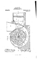
In the accompanying drawings forming a inner wings 18 which are secured to the arms part of this specification Figure 1 is a sec- 15 and intermediate disk 16 may be radial,
tional elevation o my improved fan arbut preferably curve backward froin'the di- 75 ranged in a suitable casing with doors, etc., rection of rotation to facilitate the radial whereby the fan may be employed for forcdelivery of the air drawn into the fan.
ing air into a mine or withdrawing it there- Outer wings 19 and 2() are arranged between from; Fig. 2 is a similar view of a double the annular plates 17 and the intermediate or high service fan embodying my improvedisk 16. The wings are preferably formed 80 ments', Fig. 3 is a sectional plan view on with opposite curvatures, the wing 19 having a plane indicated by the line lll-lll Fig. its inner portion concave and outer portion 2, and Fig. 4 is a view similar to Fig. convex in the direction of rotation, while illustrating a modification of the constructhe wing 20 forming the other member o tion shown in said figure. the pair, as these wings may be convenient y 85 ln the practice of my invention the fan is termed, has its inner portion convex and its arranged in a casing 1 having openings outer portion concave in direction of rotainto side chambers or channels 3 which comtion of the fan. It will be observed that municate at their respective ends with the these are not strictly radial but incline from mine entrance i and with the air. rlhe flow their inner ends back from the direction of 90 of fresh air into these chambers is controlled rotation of the fan. The amount of inclinaby doors 5, and the flow of foul air from the tion may be varied as can also the curvature mine into the same chambers is controlled by of the wings, which can be made straight. The wings comprising a pair are preferably doors 6. The fan is mounted on a sha mounted concentrically with the openings 2 arranged more nearly adjacent to each other 95 through which air is drawn from the chamthan the pairs of wings, and these pairs are bers into the center of the fan, and periphso spaced relative to the inner wings 18 that erally discharged into the spiral passage air is mainly directed by the latter between between the periphery of the fan and casthe members of alternate pairs o outer wings. The pair of outer wings in the rear 100 ing 1. This spira passage communicates with the mine and with a chimney 9. The of the inner wings should be preferablyl arranged in such relation to the inner wings How of air from the chamber is controlled by a sectional valve or door 10, 11, fully dethat air flowingV back over the outer ends o these wings 1S will be delivered into the scribed and claimed in an application Seria 50 No. 328,092,6led by me July 27 1906. This spaces between pairs. of wings 19, 2O and 105 door, which is arranged in the casing, is adapted to be shifted from a position transverse of the chimney to a position transverse 55 of the connection of the spiral passage .8 with the mine entrance 4. The flow o air between adjacent pairs of wings. lt will be observed that the inner win -s4 do not extend to the circle passing through the inner ends of wings 19, 20, but have their outer ends bent back to form passages or n0 that the greater volume of air delivered by long the front part of the air will however pass through the openings a and flow outwardly through the spaces between adjacent wings 19a. iot wings 2l may be arranged between adjacent wingsl 19aL or adjacent pairs of wings 19, 20.
In order to avoid the formation of eddies in the rear of wings 19, the spaces between adjacent wings 19a, and etween the wings 9`20 of the pairs, two vanes 22`23 are arranged in the rear of wings 19a, as shown in Fig. 4, an extend into the spaces between The vanes are arranged in V-shaped having` their inner contactft'ording openings for the outward The Vanes are also arranged portions of 20, that air passing along fl of the wino's 19il and the front I flow rapidly through the passages or gullets and e will create radial blasts or currents flowing out radiall. thus preventing the formation of retarding eddies.
' the fans are con` more series of wings faces of the as shown in l4 series of wings and vanes and also the inner wings ai'e preferably constructed and arranged as in the consti'uction shown in Fig. 2. The main wings 24, 24Fl of the intermediate series are so arranged that alternate wings 24 have their inner ends in or approximately. in line radially with the outer ends of the wings 18 while the other wings 24t are arranged approximately half Way between the wings 24. ilot wings 25 are arranged between the wings 24 and and 24a and provision is made for breaking ings between their inner ends to permit a Il wings 24C and 24a, are arranged in suoli relation to the latter, as to form therewith outwardly contracting passages through which air will flow as a blast or jet preventing the formation of eddies.
20, as shown in Figs. l j
and 20, openings or gullets being their inner the formation of a blast of air which will prevent the formation of eddies between e pairs of wings. It will be observed that this gullet between the vanes 29, 30 is in line or approximately in line radially with the pilot wing 21, which is adapted to direct a portion of tie air flowing outwardly between the pairs of wings 19, 20, forward toward the gullet between vanes 29 and 30.
n application Serial and described space is provided between the inner and outer wings for th across the outer also a construction in which a iary wing is arranged in the main outer form a passage in the rear of the main wing to cause the to prevent the entirely destroy when produced by the wing. as my invention:
Vane
outer wings y away from the direction of rotation; the inner and outer series of wings being so constructed and arranged as to provide openings between adjacent ends of the inner and outer series; the wings of the inner series arranged with their outer ends in or approximately in line radially with the inner ends of alternate wings of one of the outer series.
2. A fan having in combination an inner series of wings, ter wings having an inclination away from the direcin the rear of the outer series arranged adjacent to the periphadapted in connection with adjacent wings to produce blasts or streams of formation of eddies in the rear of the main wings is prevented.
in combination a series of inner wings7 wings, and l arated a distance from the inner ends of the outer wings, thereby f k the backward How of air between the inner anc outer series of wings.
5. A fan having in combination a series of inner wings, a series of pairs of outer wings and pairs of vanes arranged between and at an angle to the pairs of outer wings7 and having openings or spaces between the inner ends of each pair.
6. A fan having in combination a series of inner wings, and two series of outer wings, the adjacent wings of the two series being so arranged relative to each other that the passage between them gradually increases in width toward the periphery of the fan, and vanes arranged between said adjacent wings and oppositely inclined relatively to such wings and to each other.
7. A fan having in combination a series of inner wings, a series of outer wings, vanes arranged between the outer wings and at an angle to the outer wings and to each other, thereby forming V-shaped spaces and pilot wings arranged in or approximately in line radially with the apices of the spaces formed by the vanes.
8. A fan having in combination a series of inner wings, two series of reversely curved wings extending from the inlet the wings of the two series being oppositely arranged and vanes arranged in V-shaped relation to each other between the two series of outer wings so that the wider portion of the space between the vanes will be toward the periphery of the fan.
9. In a centrifugal fan, a wing constrnetion including a wing extending outward from the eye of the fan toward the periphery and a vane arranged rearward of said wing adjacent to the outer end of the latter and forming with said wing, a passagej way for air along the rear surface of said wing, said passageway contacting outwardly with substantial uniformity, substantially as described.
10. In a centrifugal fan, a tion including a wing extending outward from the eye of the fan toward the periphery, a vane arranged rearward of said wing adjacent to its outer end and spaced therefrom to form a passageway for air along the rear surface of said wing, and a second wing arranged rearward of the first and extending outward from the eye of the fan and arranged to form with the rst wing a passageway through which air is fed to the passageway formed by the vane and first wing, substantially as described.
11. In a centrifugal fan, a wing construction including a wing extending outward from the eye of the fan toward the periphery and inwardly converging vanes arranged rearward of said wing and adjacent to its outer end, one of the vanes forming with said wing a passageway for air flowing over the rear surface of said wing, substantially as described.
12. In a centrifugal fan, a wing construction including a wing extending outward from the eye of the fan toward the periphery, and vanes arranged rearward of said wing and adjacent to its outer end, said vanes diverging outwardly, and the inner ends of said vanes being separated to form a passage for the outward flow of air, substantially as described.
13. In a centrifugal fan, tion including a pair of wings extending outward from the eye of the fan toward the periphery and forming between them a passageway for air, and outwardly diverging vanes arranged adjacent to the outer ends of said wings, the inner ends of the vanes lying in the passageway substantially as described.
1li. In a Ventilating fan the combination with a wing extending outward from the eye or inlet of the fan toward the periphery, but not reaching the periphery, two converging vanes extending inward from the periphery and arranged rearward of said lirst named wing with a space between, substantially as described.
In testimony whereof, I have hereunto set my hand.
WILLIAM CLIFFORD.
a wing construcwing construc- Iifitnesses CHARLES BARNETT, F. J. ToMAssoN.
between said wings,
Priority Applications (1)
| Application Number | Priority Date | Filing Date | Title |
|---|---|---|---|
| US48523009A US963278A (en) | 1909-03-23 | 1909-03-23 | Ventilating apparatus. |
Applications Claiming Priority (1)
| Application Number | Priority Date | Filing Date | Title |
|---|---|---|---|
| US48523009A US963278A (en) | 1909-03-23 | 1909-03-23 | Ventilating apparatus. |
Publications (1)
| Publication Number | Publication Date |
|---|---|
| US963278A true US963278A (en) | 1910-07-05 |
Family
ID=3031676
Family Applications (1)
| Application Number | Title | Priority Date | Filing Date |
|---|---|---|---|
| US48523009A Expired - Lifetime US963278A (en) | 1909-03-23 | 1909-03-23 | Ventilating apparatus. |
Country Status (1)
| Country | Link |
|---|---|
| US (1) | US963278A (en) |
Cited By (1)
| Publication number | Priority date | Publication date | Assignee | Title |
|---|---|---|---|---|
| US20140044575A1 (en) * | 2011-01-05 | 2014-02-13 | Borgwarner Inc. | Impeller design for fluid pump assembly and method of making |
-
1909
- 1909-03-23 US US48523009A patent/US963278A/en not_active Expired - Lifetime
Cited By (1)
| Publication number | Priority date | Publication date | Assignee | Title |
|---|---|---|---|---|
| US20140044575A1 (en) * | 2011-01-05 | 2014-02-13 | Borgwarner Inc. | Impeller design for fluid pump assembly and method of making |
Similar Documents
| Publication | Publication Date | Title |
|---|---|---|
| US820398A (en) | Centrifugal fan or pump. | |
| US1603966A (en) | Turbine rotor | |
| US351129A (en) | Dale and john fraser | |
| US963277A (en) | Ventilating apparatus. | |
| US1604328A (en) | Centrifugal fan | |
| US963690A (en) | Rotary pump. | |
| US1138083A (en) | Rotary fan. | |
| US949150A (en) | Centrifugal fan. | |
| US1233275A (en) | Air-compressor. | |
| US978397A (en) | Fan. | |
| US909863A (en) | Centrifugal fan. | |
| US1074606A (en) | Fan-blower. | |
| US1056288A (en) | Rotary blower. | |
| US100838A (en) | Improvement in cehtrifugal pujtffs | |
| US132829A (en) | Improvement in rotary engines and fuwips | |
| US1030561A (en) | Fan. | |
| US1390237A (en) | Blower and exhauster for moving air and gas | |
| US935114A (en) | Rotary fan. | |
| US1561847A (en) | Compound turbine blower | |
| US447909A (en) | Ntover | |
| US533292A (en) | Rotary blower | |
| US1099921A (en) | Centrifugal pump. | |
| US593219A (en) | Rotary engine | |
| US911492A (en) | Turbine. | |
| US1495873A (en) | Fan or impeller |