US9631626B1 - Single screw blade arms - Google Patents
Single screw blade arms Download PDFInfo
- Publication number
- US9631626B1 US9631626B1 US13/782,242 US201313782242A US9631626B1 US 9631626 B1 US9631626 B1 US 9631626B1 US 201313782242 A US201313782242 A US 201313782242A US 9631626 B1 US9631626 B1 US 9631626B1
- Authority
- US
- United States
- Prior art keywords
- cylindrical
- blade
- base
- fastener
- arm
- Prior art date
- Legal status (The legal status is an assumption and is not a legal conclusion. Google has not performed a legal analysis and makes no representation as to the accuracy of the status listed.)
- Active, expires
Links
- 238000000034 method Methods 0.000 abstract description 8
- 235000000396 iron Nutrition 0.000 abstract description 5
- XEEYBQQBJWHFJM-UHFFFAOYSA-N Iron Chemical compound [Fe] XEEYBQQBJWHFJM-UHFFFAOYSA-N 0.000 description 8
- 238000009434 installation Methods 0.000 description 4
- 229910052742 iron Inorganic materials 0.000 description 4
- 230000008901 benefit Effects 0.000 description 2
- 238000012986 modification Methods 0.000 description 2
- 230000004048 modification Effects 0.000 description 2
Images


Classifications
-
- F—MECHANICAL ENGINEERING; LIGHTING; HEATING; WEAPONS; BLASTING
- F04—POSITIVE - DISPLACEMENT MACHINES FOR LIQUIDS; PUMPS FOR LIQUIDS OR ELASTIC FLUIDS
- F04D—NON-POSITIVE-DISPLACEMENT PUMPS
- F04D25/00—Pumping installations or systems
- F04D25/02—Units comprising pumps and their driving means
- F04D25/08—Units comprising pumps and their driving means the working fluid being air, e.g. for ventilation
- F04D25/088—Ceiling fans
-
- F—MECHANICAL ENGINEERING; LIGHTING; HEATING; WEAPONS; BLASTING
- F04—POSITIVE - DISPLACEMENT MACHINES FOR LIQUIDS; PUMPS FOR LIQUIDS OR ELASTIC FLUIDS
- F04D—NON-POSITIVE-DISPLACEMENT PUMPS
- F04D29/00—Details, component parts, or accessories
- F04D29/26—Rotors specially for elastic fluids
- F04D29/32—Rotors specially for elastic fluids for axial flow pumps
- F04D29/34—Blade mountings
-
- F—MECHANICAL ENGINEERING; LIGHTING; HEATING; WEAPONS; BLASTING
- F04—POSITIVE - DISPLACEMENT MACHINES FOR LIQUIDS; PUMPS FOR LIQUIDS OR ELASTIC FLUIDS
- F04D—NON-POSITIVE-DISPLACEMENT PUMPS
- F04D29/00—Details, component parts, or accessories
- F04D29/60—Mounting; Assembling; Disassembling
- F04D29/64—Mounting; Assembling; Disassembling of axial pumps
- F04D29/644—Mounting; Assembling; Disassembling of axial pumps especially adapted for elastic fluid pumps
- F04D29/646—Mounting or removal of fans
-
- F—MECHANICAL ENGINEERING; LIGHTING; HEATING; WEAPONS; BLASTING
- F04—POSITIVE - DISPLACEMENT MACHINES FOR LIQUIDS; PUMPS FOR LIQUIDS OR ELASTIC FLUIDS
- F04D—NON-POSITIVE-DISPLACEMENT PUMPS
- F04D29/00—Details, component parts, or accessories
- F04D29/26—Rotors specially for elastic fluids
- F04D29/32—Rotors specially for elastic fluids for axial flow pumps
- F04D29/34—Blade mountings
- F04D29/36—Blade mountings adjustable
Definitions
- This invention relates blade connecting devices, and in particular to devices, systems and methods of using blade arm brackets/irons using only a single screw fastener with two or three mounted posts to align and lock ceiling fan blades to a ceiling fan blade brackets/irons.
- ceiling fan blades It is common to attach ceiling fan blades to blade brackets and holders of ceiling fans by screwing fasteners, such as screws, to attach the blades to ceiling fan brackets, where the brackets are attached to motors. Ceiling fan blades are difficult and tedious to assemble. Several small screws and washers need to be screwed through the blade and into the blade holder using a screw driver while holding the blade and blade holder in place.
- U.S. Pat. No. 6,758,626 to Tseng uses twistable knobs to attach blades in a ceiling fan.
- this device requires three twistable knobs, and that each of the knobs and their support posts must be oval shaped, and also requires keeping an air space between the blade and the arm in the locked position, which ends of with multiple parts and assembly time.
- U.S. Pat. No. 6,932,576 to Bird shows and describes a connecting mechanism which uses one twisting knob.
- this device requires the installer to catch upwardly protruding inverted L shaped fasteners on a blade bracket to catch into holes in the blade.
- a separated knob must be then inserted into another hole in the blade to be twisted. Having separated parts, such as the separate knob, can be easily lost and misplaced, similar to loose screws that are used to traditionally attach ceiling blades to ceiling fans.
- the catches can make it difficult for someone to angle the blade to assemble.
- a primary objective of the present invention is to provide devices, systems and methods of using blade arm brackets/irons with a single screw fastener with two or three mounted posts to align and lock ceiling fan blades to a ceiling fan blade arm brackets/irons.
- a secondary objective of the present invention is to provide devices, systems and methods of soundly connecting a blade to a blade holder without using more than one screw type fastener.
- the novel invention device, system and method requires no tools, loose parts, or hardware.
- the blade is simply aligned and placed over the locating pins in the blade holder and locked into place by rotating the fastener.
- the claimed invention differs from what currently exists.
- Our invention requires only one screw type fastener. The entire assembly process takes seconds compared to several minutes for other systems.
- a ceiling fan blade arm can consist essential of a blade attachment end having only one single rotatable fastener and at least two alignment posts, wherein the single screw and at least two alignment posts are adapted to pass into at least three through-holes on a root end of a blade in order to attach the blade to the arm.
- the single rotatable fastener can be positioned in the middle of three posts, and the blade includes four through-holes.
- the rotatable fastener can be a screw.
- Two posts can be positioned outward facing from the middle rotatable fastener on the blade attachment end of the blade arm and one post is positioned inward facing from the middle rotatable fastener.
- Two posts can be positioned inward facing from the middle rotatable fastener on the blade attachment end of the blade arm and one post is positioned outward facing from the middle rotatable fastener.
- Two posts can be positioned inward facing from the blade attachment end and the rotatable fastener is positioned outward facing, wherein the two posts and rotatable fastener form a triangular arrangement.
- Two posts can be positioned outward facing from the blade attachment end and the rotatable fastener is positioned inward facing, wherein the two posts and rotatable fastener form a triangular arrangement.
- a ceiling fan blade attachment system can include a plurality of blade arm, each blade arm consisting essentially of a blade attachment end having only one single rotatable fastener and at least two alignment posts, wherein the single screw and at least two alignment posts, and a plurality of fan blades, each blade having at least three through-holes on a root end of the blade, wherein the single rotatable fastener and the at least two alignment posts are adapted to pass into at least three through-holes on the root ends of a blades.
- the single rotatable fastener on each arm can be positioned in the middle of three posts on each arm, and each blade includes four through-holes.
- Two posts can be positioned outward facing from the middle rotatable fastener on each blade attachment end of the blade arm and one post is positioned inward facing from the middle rotatable fastener on each blade attachment end of each blade arm.
- Two posts can be positioned inward facing from the middle rotatable fastener on each blade attachment end of the blade arm and one post is positioned outward facing from the middle rotatable fastener on each blade attachment end of each blade arm.
- Two posts can be positioned inward facing from each blade attachment end and the rotatable fastener is positioned outward facing, wherein the two posts and rotatable fastener form a triangular arrangement on each blade attachment end of each blade arm, and each blade has only three through-holes on the root end of the blade.
- Two posts can be positioned outward facing from each blade attachment end and the rotatable fastener is positioned inward facing, wherein the two posts and rotatable fastener form a triangular arrangement on each blade attachment end of each blade arm, and each blade has only three through-holes on the root end of the blade.
- a method of attaching a ceiling fan blade to a motor arm with a single rotatable fastener can include the steps of providing a blade having a root end with at least three through holes arranged in a triangular pattern, providing a blade arm having a blade attachment end with a single rotatable fastener and at least two posts, removing the rotatable fastener from the blade arm, aligning the at least three through-holes on the root end of the blade over the at least three through-holes on the blade attachment end of the arm, rotating the single rotatable fastener through a single through-hole in the blade attachment end of the arm to attach the blade to the blade arm, and repeating the above steps for attaching additional blades to the blade attachment arms on a ceiling fan.
- the method can include the step of providing a single screw as the rotatable fastener to attach each blade to each blade arm.
- FIG. 1 is a plan view of a single rotatable fastener blade arm having two outward facing posts and one inward post with fan blade.
- FIG. 2 is a top right perspective view of the arm of FIG. 1 .
- FIG. 3 is a top left perspective view of the arm of FIG. 1 .
- FIG. 4 is a top view of the arm of FIG. 1 .
- FIG. 5 is a bottom view of the arm of FIG. 1 .
- FIG. 6 is an upside down side view the arm of FIG. 1 .
- FIG. 7 is a side view of the arm of FIG. 1 .
- FIG. 8 is a root end view of the arm of FIG. 1 .
- FIG. 9 is a tip of the arm of FIG. 1 .
- FIG. 10 is a top right perspective view of a single rotatable fastener blade arm with two inward facing posts and one outward post.
- FIG. 11 is a top left perspective view of the arm of FIG. 10 .
- FIG. 12 is a top view of the arm of FIG. 10 .
- FIG. 13 is a bottom view of the arm of FIG. 10 .
- FIG. 14 is an upside down side view the arm of FIG. 10 .
- FIG. 15 is a side view of the arm of FIG. 10 .
- FIG. 16 is a root end view of the arm of FIG. 10 .
- FIG. 17 is a tip end view of the arm of FIG. 1 .
- FIG. 18 is a top right perspective view of a single rotatable fastener blade arm with only two inward facing posts.
- FIG. 19 is a top left perspective view of the arm of FIG. 18 .
- FIG. 20 is a top view of the arm of FIG. 18 .
- FIG. 21 is a bottom view of the arm of FIG. 18 .
- FIG. 22 is an upside down side view of the arm of FIG. 18 .
- FIG. 23 is a side view of the arm of FIG. 18 .
- FIG. 24 is a root end view of the arm of FIG. 18 .
- FIG. 25 is a tip end view of the arm of FIG. 18 .
- FIG. 26 is a top right perspective view of a single rotatable fastener blade arm with only two outward facing posts.
- FIG. 27 is a top left perspective view of the arm of FIG. 26 .
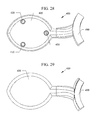
- FIG. 28 is a top view of the arm of FIG. 26 .
- FIG. 29 is a bottom view of the arm of FIG. 26 .
- FIG. 30 is an upside down side view of the arm of FIG. 26 .
- FIG. 31 is a side view of the arm of FIG. 26 .
- FIG. 32 is a root end view of the arm of FIG. 26 .
- FIG. 33 is a tip end view of the arm of FIG. 26 .
- FIG. 1 is a plan view of a single rotatable fastener blade arm 100 having two outward facing posts 110 , 120 and one inward post 130 with fan blade 1 .
- FIG. 2 is a top right perspective view of the arm 100 of FIG. 1
- FIG. 3 is a top left perspective view of the arm 100 of FIG. 1 .
- FIG. 4 is a top view of the arm 100 of FIG. 1 .
- FIG. 5 is a bottom view of the arm 100 of FIG. 1 .
- FIG. 6 is an upside down side view the arm 100 of FIG. 1 .
- FIG. 7 is a side view of the arm 100 of FIG. 1 .
- FIG. 8 is a root end view of the arm 100 of FIG. 1 .
- FIG. 9 is a tip of the arm 100 of FIG. 1 .
- the novel blade arm 100 can have a blade attachment end 105 for attaching the arm 100 to a ceiling fan blade 1 , and a motor attachment end 190 for attaching the arm 100 to a motor on a ceiling fan.
- the blade attachment end 105 can have three upwardly protruding posts 110 , 120 , 130 arranged in a triangular configuration with two outward facing posts 110 , 120 and one inward facing post 130 .
- Each post 110 - 130 can have an enlarged base with a narrower upwardly extending tip portion.
- the blade attachment end 105 of the arm 100 can have middle raised base 155 generally located in the middle of the posts 110 , 120 and 130 that can support a single rotatable fastener 150 , such as a screw and the like.
- the rotatable fastener 150 can threadably attach to a threaded opening in the top of the raised base 155 .
- the blade attachment end 5 of the ceiling fan blade 1 can be laid over the blade attachment end 105 of the blade arm 105 and lined up so that the top of each of the three posts 110 , 120 , 130 pass through the holes 10 , 20 , 30 of the blade 1 .
- the bottom of the arm attachment end 5 of the blade can generally rest on the upper edge portion of the base of each of the posts 110 , 120 , 130 , so that the tip ends of each post 110 , 120 , 130 protrude upward from the top of the arm attachment end 5 of the blade 1 .
- the rotatable fastener can be screwed into the central opening 40 in the arm attachment end 5 of the blade 1 so that outer edges of the enlarged head portion of the rotatable fastener 150 abut against upper surface portion of the top of arm attachment end 5 of the blade 1 to hold the blade to the arm.
- Each other blade can be attached to respective blade arms in a similar manner until all the blades are attached to all of the arms of the ceiling fan.
- Each blade can be attached to each arm by only a single rotatable fastener for each blade.
- FIG. 10 is a top right perspective view of a single rotatable fastener blade arm 200 with two inward facing posts 220 , 230 and one outward post 210 .
- FIG. 11 is a top left perspective view of the arm 200 of FIG. 10 .
- FIG. 12 is a top view of the arm 200 of FIG. 10 .
- FIG. 13 is a bottom view of the arm 200 of FIG. 10 .
- FIG. 14 is an upside down side view the arm 200 of FIG. 10 .
- FIG. 15 is a side view of the arm 200 of FIG. 10 .
- FIG. 16 is a root end view of the arm 200 of FIG. 10 .
- FIG. 17 is a tip end view of the arm 200 of FIG. 1 .
- the novel blade arm 200 can have a blade attachment end 205 for attaching the arm 200 to a ceiling fan blade 1 , and a motor attachment end 290 for attaching the arm 200 to a motor on a ceiling fan.
- the blade attachment end 205 can have three upwardly protruding posts 210 , 220 , 230 arranged in a triangular configuration with one outward facing post 210 and two inward facing posts 220 , 230 .
- Each post 210 - 230 can have an enlarged base with a narrower upwardly extending tip portion.
- the blade attachment end 205 of the arm 200 can have middle raised base 255 generally located in the middle of the posts 210 , 220 and 230 that can support a single rotatable fastener 250 , such as a screw and the like.
- the rotatable fastener 250 can threadably attach to a threaded opening in the top of the raised base 255 .
- the blade arm 200 can be attached to a blade in a similar manner to the previous embodiment.
- the blade 1 of the previous embodiment can have a different hole pattern having two inwardly facing through holes and one outwardly facing through hole and central hole for the rotatable fastener 250 .
- the user can remove the rotatable fastener 255 from the raised base 250 .
- the blade attachment end of the ceiling fan blade can be laid over the blade attachment end 205 of the blade arm 205 and lined up so that the top of each of the three posts 210 , 220 , 230 pass through respective holes of the blade.
- the bottom of the arm attachment end of the blade can generally rest on the upper edge portion of the base of each of the posts 210 , 220 , 230 , so that the tip ends of each post 210 , 220 , 230 protrude upward from the top of the arm attachment end of the blade.
- the rotatable fastener 250 can be screwed into the central opening in the arm attachment end of the blade so that outer edges of the enlarged head portion of the rotatable fastener 250 abut against upper surface portion of the top of arm attachment end of the blade to hold the blade to the arm.
- Each other blade can be attached to respective blade arms in a similar manner until all the blades are attached to all of the arms of the ceiling fan.
- Each blade can be attached to each arm by only a single rotatable fastener for each blade.
- FIG. 18 is a top right perspective view of a single screw blade arm 300 with only two inward facing posts 310 , 320 and one rotatable fastener (apex of triangle pattern).
- FIG. 19 is a top left perspective view of the arm 300 of FIG. 18 .
- FIG. 20 is a top view of the arm 300 of FIG. 18 .
- FIG. 21 is a bottom view of the arm 300 of FIG. 18 .
- FIG. 22 is an upside down side view of the arm 300 of FIG. 18 .
- FIG. 23 is a side view of the arm of FIG. 18 .
- FIG. 24 is a root end view of the arm 300 of FIG. 18 .
- FIG. 25 is a tip end view of the arm 300 of FIG. 18 .
- the novel blade arm 300 can have a blade attachment end 305 for attaching the arm 300 to a ceiling fan blade, and a motor attachment end 390 for attaching the arm 300 to a motor on a ceiling fan.
- the blade attachment end 305 can have two inward facing posts 310 , 320 and one outward facing rotatable fastener 350 on a base 355 arranged in a triangular configuration.
- Each post 310 , 320 can have an enlarged base with a narrower upwardly extending tip portion.
- the blade attachment end 305 of the arm 300 can have outward facing raised base 355 that can support a single rotatable fastener 350 , such as a screw and the like.
- the rotatable fastener 350 can threadably attach to a threaded opening in the top of the raised base 355 .
- the blade arm 300 can be attached to a blade in a similar manner to the previous embodiment.
- the blade 1 of the previous embodiment can have a different hole pattern having two outward through holes and one inwardly facing through hole (a total of only three holes).
- the user can remove the rotatable fastener 355 from the raised base 350 .
- the blade attachment end of the ceiling fan blade can be laid over the blade attachment end 305 of the blade arm and lined up so that the top of each of the posts 310 , 320 pass through respective holes of the blade.
- the bottom of the arm attachment end of the blade can generally rest on the upper edge portion of the base of each of the posts 310 , 320 , so that the tip ends of each post 310 , 320 protrude upward from the top of the arm attachment end of the blade.
- the rotatable fastener 350 can be screwed into the central opening in the arm attachment end of the blade so that outer edges of the enlarged head portion of the rotatable fastener 350 can abut against upper surface portion of the top of arm attachment end of the blade.
- Each other blade can be attached to respective blade arms in a similar manner until all the blades are attached to all of the arms of the ceiling fan.
- Each blade can be attached to each arm by only a single rotatable fastener for each blade.
- FIG. 26 is a top right perspective view of a single rotatable fastener blade arm 400 with only two outward facing posts 410 , 420 and one inwardly facing single rotatable fastener 450 .
- FIG. 27 is a top left perspective view of the arm 400 of FIG. 26 .
- FIG. 28 is a top view of the arm 400 of FIG. 26 .
- FIG. 29 is a bottom view of the arm 400 of FIG. 26 .
- FIG. 30 is an upside down side view of the arm 400 of FIG. 26 .
- FIG. 31 is a side view of the arm 400 of FIG. 26 .
- FIG. 32 is a root end view of the arm 400 of FIG. 26 .
- FIG. 33 is a tip end view of arm 400 of FIG. 26 .
- the novel blade arm 400 can have a blade attachment end 405 for attaching the arm 400 to a ceiling fan blade, and a motor attachment end 490 for attaching the arm 400 to a motor on a ceiling fan.
- the blade attachment end 405 can have two outward facing posts 410 , 420 and one inward facing rotatable fastener 450 on a base 455 arranged in a triangular configuration.
- Each post 410 , 420 can have an enlarged base with a narrower upwardly extending tip portion.
- the blade attachment end 405 of the arm 400 can have inward facing raised base 455 that can support a single rotatable fastener 450 , such as a screw and the like.
- the rotatable fastener 450 can threadably attach to a threaded opening in the top of the raised base 455 .
- the blade arm 400 can be attached to a blade in a similar manner to the previous embodiment.
- the blade of the previous embodiment can have a different hole pattern having two inward through holes and one outward facing through hole (a total of only three holes).
- the user can remove the rotatable fastener 455 from the raised base 450 .
- the blade attachment end of the ceiling fan blade can be laid over the blade attachment end 405 of the blade arm and lined up so that the top of each of the posts 410 , 420 pass through respective holes of the blade.
- the bottom of the arm attachment end of the blade can generally rest on the upper edge portion of the base of each of the posts 410 , 420 , so that the tip ends of each post 410 , 420 protrude upward from the top of the arm attachment end of the blade.
- the rotatable fastener 450 can be screwed into the central opening in the arm attachment end of the blade so that outer edges of the enlarged head portion of the rotatable fastener 450 can abut against upper surface portion of the top of arm attachment end of the blade.
- Each other blade can be attached to respective blade arms in a similar manner until all the blades are attached to all of the arms of the ceiling fan.
- Each blade can be attached to each arm by only a single rotatable fastener for each blade.
Landscapes
- Engineering & Computer Science (AREA)
- Mechanical Engineering (AREA)
- General Engineering & Computer Science (AREA)
- Structures Of Non-Positive Displacement Pumps (AREA)
Abstract
Description
- 1. blade
- 5. root/arm end of blade
- 10. first fastening hole
- 20. second fastening hole
- 30. third fastening hole
- 40. middle hole
- 100. First Blade Iron with single screw in middle of three posts (two outward).
- 105. Blade attachment end
- 110. first post
- 120. second post
- 130. third post
- 150. middle rotatable fastener
- 155. base
- 190. motor attachment end
- 200. Second Blade Iron with single screw in middle of three posts (inward outward).
- 205. Blade attachment end
- 210. first post
- 220. second post
- 230. third post
- 250. middle rotatable fastener
- 255. base
- 290. motor attachment end
- 300. Third Blade Iron with single screw and two inward posts.
- 305. blade attachment end
- 310. first post
- 320. second post
- 350. single rotatable fastener (apex of triangle pattern)
- 355. base
- 390. motor attachment end
- 400. Fourth Blade Iron with single screw and two outward posts.
- 405. blade attachment end
- 410. first post
- 420. second post
- 450. single rotatable fastener (apex of triangle pattern)
- 455. base
- 490. motor attachment end
Claims (12)
Applications Claiming Priority (2)
| Application Number | Priority Date | Filing Date | Title |
|---|---|---|---|
| US201261603072P | 2012-02-24 | 2012-02-24 | |
| US13/459,568 US8985959B1 (en) | 2012-02-24 | 2012-04-30 | Turning knob blade locking device, system and method |
Publications (1)
| Publication Number | Publication Date |
|---|---|
| US9631626B1 true US9631626B1 (en) | 2017-04-25 |
Family
ID=52683237
Family Applications (2)
| Application Number | Title | Priority Date | Filing Date |
|---|---|---|---|
| US13/459,568 Active 2033-06-14 US8985959B1 (en) | 2012-02-24 | 2012-04-30 | Turning knob blade locking device, system and method |
| US13/782,242 Active 2034-07-16 US9631626B1 (en) | 2012-02-24 | 2013-03-01 | Single screw blade arms |
Family Applications Before (1)
| Application Number | Title | Priority Date | Filing Date |
|---|---|---|---|
| US13/459,568 Active 2033-06-14 US8985959B1 (en) | 2012-02-24 | 2012-04-30 | Turning knob blade locking device, system and method |
Country Status (1)
| Country | Link |
|---|---|
| US (2) | US8985959B1 (en) |
Families Citing this family (6)
| Publication number | Priority date | Publication date | Assignee | Title |
|---|---|---|---|---|
| US8985959B1 (en) | 2012-02-24 | 2015-03-24 | Palm Coast Imports, LLC | Turning knob blade locking device, system and method |
| WO2017106316A1 (en) | 2015-12-14 | 2017-06-22 | Hunter Fan Company | Ceiling fan |
| US11674526B2 (en) | 2016-01-22 | 2023-06-13 | Hunter Fan Company | Ceiling fan having a dual redundant motor mounting assembly |
| CN106593913A (en) * | 2017-01-10 | 2017-04-26 | 广东美的环境电器制造有限公司 | Ceiling fan vane mounting structure and ceiling fan |
| CN108757567A (en) * | 2018-05-22 | 2018-11-06 | 张健祥 | A kind of New Type of Fan fan leaf and preparation method thereof |
| CN109795789A (en) * | 2019-01-02 | 2019-05-24 | 佛山市吉星家电有限公司 | A kind of fixed bracket of transport of electric fan guard and flabellum |
Citations (57)
| Publication number | Priority date | Publication date | Assignee | Title |
|---|---|---|---|---|
| US3549184A (en) | 1969-02-10 | 1970-12-22 | Keystone Consolidated Ind Inc | Flush safety latch |
| US4186952A (en) | 1978-07-27 | 1980-02-05 | Keystone Consolidated Industries, Inc. | Turn button latch |
| US4331413A (en) | 1980-01-21 | 1982-05-25 | Simmons Fastener Corporation | Quarter turn plug fastener |
| US4420859A (en) | 1981-10-05 | 1983-12-20 | Trw Inc. | Two-part panel fastener |
| USD382955S (en) | 1996-06-13 | 1997-08-26 | Liu Chen-Tzu | Ceiling fan bracket |
| US5980353A (en) * | 1998-12-02 | 1999-11-09 | Wu; San-Chi | Connecting device for connecting a fan blade to a rotor of a motor if a ceiling fan |
| US6042339A (en) | 1998-06-16 | 2000-03-28 | Aloha Housewares Co., Ltd. | Ceiling fan assembly and method for assembling same |
| US6155786A (en) * | 1999-06-17 | 2000-12-05 | Aloha Housewares Co., Ltd | Ceiling fan assembly and method for assembling same |
| USD441442S1 (en) | 1999-09-03 | 2001-05-01 | Litex Industries, Inc. | Ceiling fan |
| US6241475B1 (en) * | 1999-02-03 | 2001-06-05 | Aloha Housewares Co., Ltd. | Ceiling fan assembly and method for assembling same |
| US6267543B1 (en) | 1999-10-13 | 2001-07-31 | Avaya Technology Corp. | Latch with spring |
| US6309183B1 (en) * | 1997-05-05 | 2001-10-30 | King Of Fans, Inc. | Blade arm |
| US20010046442A1 (en) * | 1997-05-05 | 2001-11-29 | King Of Fans, Inc. | Quick install blade arms for ceiling fans |
| US6352409B1 (en) * | 1999-09-15 | 2002-03-05 | Aloha Housewares Co., Ltd. | Ceiling fan assembly and method for assembling same |
| US6371729B1 (en) * | 2000-12-05 | 2002-04-16 | Tien Fu Tseng | Assembling structure for vane and vane bracket of ceiling fan |
| US6585488B1 (en) * | 2000-02-25 | 2003-07-01 | King Of Fans, Inc. | Ceiling fan blade isolation system |
| USD478382S1 (en) | 2002-06-20 | 2003-08-12 | Hunter Fan Company | Ceiling fan blade iron |
| USD482774S1 (en) | 2002-10-03 | 2003-11-25 | Hunter Fan Company | Ceiling fan blade iron |
| USD483465S1 (en) | 2003-03-04 | 2003-12-09 | Jen-Lung David Tai | Combined ceiling fan and light fixture |
| US6666652B2 (en) | 1997-05-05 | 2003-12-23 | King Of Fans, Inc. | Slide in, hook and fold out ceiling fan blades |
| USD485902S1 (en) | 2003-03-27 | 2004-01-27 | Hunter Fan Company | Ceiling fan blade iron |
| US6758626B1 (en) * | 2003-01-09 | 2004-07-06 | Min-Chi Tseng | Connecting device of a ceiling fan for connecting a blade to a bracket |
| US20040219023A1 (en) * | 2003-05-01 | 2004-11-04 | Bird Gregory Michael | Quick connect ceiling fan blade |
| US6863499B2 (en) * | 2002-07-12 | 2005-03-08 | Hunter Fan Company | Quick connect blade iron system |
| US20050123403A1 (en) * | 2003-12-05 | 2005-06-09 | Tai Chun Y. | Ceiling fan blade mounting assembly for ceiling fan |
| US6932576B2 (en) * | 2003-04-01 | 2005-08-23 | Hunter Fan Company | Quick connect ceiling fan blade |
| US20060078431A1 (en) * | 2004-10-12 | 2006-04-13 | Frank Blateri | Apparatus and method for mounting a ceiling fixture |
| US20060140770A1 (en) * | 2004-12-28 | 2006-06-29 | Pan Air Electric Co., Ltd. | Fan blade mounting structure for ceiling fan |
| USD531305S1 (en) | 2005-11-02 | 2006-10-31 | Air Cool Industrial Co., Ltd. | Fan blade bracket |
| USD539894S1 (en) | 2004-07-09 | 2007-04-03 | King Of Fans, Inc. | Combined ceiling fan and light dome |
| US7223078B1 (en) * | 2004-11-18 | 2007-05-29 | Litex Industries, Limited, Having A General Partner Of Libco International, Llc | Rotary plate fastener for ceiling fan blades |
| USD545422S1 (en) | 2006-08-09 | 2007-06-26 | Air Cool Industrial Co., Ltd. | Ceiling fan |
| USD556886S1 (en) | 2006-11-07 | 2007-12-04 | Minka Lighting, Inc. | Blade iron |
| USD565168S1 (en) | 2007-07-25 | 2008-03-25 | Minka Lighting, Inc. | Ceiling fan |
| USD565724S1 (en) | 2007-07-25 | 2008-04-01 | Minka Lighting, Inc. | Ceiling fan blade iron |
| US20080107529A1 (en) * | 2006-11-02 | 2008-05-08 | Hunter Fan Company | Fan blade connector component with skeleton and method of manufacturing such |
| USD568983S1 (en) * | 2007-09-29 | 2008-05-13 | Air Cool Industrial Co., Ltd. | Fan blade bracket |
| USD573245S1 (en) | 2007-12-07 | 2008-07-15 | Air Cool Industrial Co., Ltd. | Ceiling fan blade holder |
| USD578636S1 (en) | 2007-12-04 | 2008-10-14 | Air Cool Industrial Co., Ltd. | Ceiling fan blade holder |
| US20090004015A1 (en) * | 2007-06-29 | 2009-01-01 | Cliff Wang | Fast-positioning device for assembling blade brackets to a motor housing of a ceiling fan |
| US7527478B2 (en) | 2006-05-19 | 2009-05-05 | Hunter Fan Company | Fan blade mounting system |
| USD594543S1 (en) | 2009-01-19 | 2009-06-16 | Air Cool Industrial Co., Ltd. | Combined ceiling fan and light kit |
| USD594540S1 (en) | 2009-01-19 | 2009-06-16 | Air Cool Industrial Co., Ltd. | Combined ceiling fan and light kit |
| USD595404S1 (en) | 2009-01-21 | 2009-06-30 | Air Cool Industrial Co., Ltd. | Fan blade bracket |
| USD597654S1 (en) | 2007-11-09 | 2009-08-04 | Chien Luen Industries Co., Ltd., Inc. | Ceiling fan blade iron |
| USD599470S1 (en) | 2009-01-29 | 2009-09-01 | Air Cool Industrial Co., Ltd. | Ceiling fan blade iron |
| US7762782B2 (en) | 2007-07-30 | 2010-07-27 | Air Cool Industrial Co., Ltd. | Quick assembly blade for a ceiling fan (2) |
| US7775771B2 (en) | 2007-08-02 | 2010-08-17 | Air Cool Industrial Co., Ltd. | Quick assembly blade for a ceiling fan |
| USD626210S1 (en) | 2010-03-25 | 2010-10-26 | Landmark Enterprise Inc. | Fan blade bracket |
| USD626213S1 (en) | 2010-03-25 | 2010-10-26 | Landmark Enterprise Inc. | Fan blade bracket |
| US20100284813A1 (en) * | 2009-05-06 | 2010-11-11 | Cliff Wang | Locking plate fast fastening ceiling fan blades |
| USD632382S1 (en) | 2010-06-25 | 2011-02-08 | Air Cool Industrial Co., Ltd. | Combined ceiling fan and light kit |
| USD649238S1 (en) | 2009-08-27 | 2011-11-22 | Chien Luen Industries Co., Ltd., Inc. | Combined ceiling fan housing and fan blade arms |
| US8356979B2 (en) | 2008-10-28 | 2013-01-22 | Hunter Fan Company | Fan blade mounting system |
| USD681185S1 (en) | 2009-08-27 | 2013-04-30 | Chien Luen Industries Co., Ltd., Inc. | Ceiling fan blade arm |
| USD710492S1 (en) | 2013-03-01 | 2014-08-05 | Palm Coast Imports, LLC | Single screw blade arm |
| US8985959B1 (en) | 2012-02-24 | 2015-03-24 | Palm Coast Imports, LLC | Turning knob blade locking device, system and method |
-
2012
- 2012-04-30 US US13/459,568 patent/US8985959B1/en active Active
-
2013
- 2013-03-01 US US13/782,242 patent/US9631626B1/en active Active
Patent Citations (62)
| Publication number | Priority date | Publication date | Assignee | Title |
|---|---|---|---|---|
| US3549184A (en) | 1969-02-10 | 1970-12-22 | Keystone Consolidated Ind Inc | Flush safety latch |
| US4186952A (en) | 1978-07-27 | 1980-02-05 | Keystone Consolidated Industries, Inc. | Turn button latch |
| US4331413A (en) | 1980-01-21 | 1982-05-25 | Simmons Fastener Corporation | Quarter turn plug fastener |
| US4420859A (en) | 1981-10-05 | 1983-12-20 | Trw Inc. | Two-part panel fastener |
| USD382955S (en) | 1996-06-13 | 1997-08-26 | Liu Chen-Tzu | Ceiling fan bracket |
| US20010046442A1 (en) * | 1997-05-05 | 2001-11-29 | King Of Fans, Inc. | Quick install blade arms for ceiling fans |
| US6309183B1 (en) * | 1997-05-05 | 2001-10-30 | King Of Fans, Inc. | Blade arm |
| US6666652B2 (en) | 1997-05-05 | 2003-12-23 | King Of Fans, Inc. | Slide in, hook and fold out ceiling fan blades |
| US20080273979A1 (en) | 1997-05-05 | 2008-11-06 | King Of Fans, Inc. | Quick install blade arms for ceiling fans |
| US6042339A (en) | 1998-06-16 | 2000-03-28 | Aloha Housewares Co., Ltd. | Ceiling fan assembly and method for assembling same |
| US5980353A (en) * | 1998-12-02 | 1999-11-09 | Wu; San-Chi | Connecting device for connecting a fan blade to a rotor of a motor if a ceiling fan |
| US6241475B1 (en) * | 1999-02-03 | 2001-06-05 | Aloha Housewares Co., Ltd. | Ceiling fan assembly and method for assembling same |
| US6155786A (en) * | 1999-06-17 | 2000-12-05 | Aloha Housewares Co., Ltd | Ceiling fan assembly and method for assembling same |
| USD441442S1 (en) | 1999-09-03 | 2001-05-01 | Litex Industries, Inc. | Ceiling fan |
| US6352409B1 (en) * | 1999-09-15 | 2002-03-05 | Aloha Housewares Co., Ltd. | Ceiling fan assembly and method for assembling same |
| US6267543B1 (en) | 1999-10-13 | 2001-07-31 | Avaya Technology Corp. | Latch with spring |
| US6585488B1 (en) * | 2000-02-25 | 2003-07-01 | King Of Fans, Inc. | Ceiling fan blade isolation system |
| US6371729B1 (en) * | 2000-12-05 | 2002-04-16 | Tien Fu Tseng | Assembling structure for vane and vane bracket of ceiling fan |
| USD478382S1 (en) | 2002-06-20 | 2003-08-12 | Hunter Fan Company | Ceiling fan blade iron |
| US6863499B2 (en) * | 2002-07-12 | 2005-03-08 | Hunter Fan Company | Quick connect blade iron system |
| USD482774S1 (en) | 2002-10-03 | 2003-11-25 | Hunter Fan Company | Ceiling fan blade iron |
| US6758626B1 (en) * | 2003-01-09 | 2004-07-06 | Min-Chi Tseng | Connecting device of a ceiling fan for connecting a blade to a bracket |
| USD483465S1 (en) | 2003-03-04 | 2003-12-09 | Jen-Lung David Tai | Combined ceiling fan and light fixture |
| USD485902S1 (en) | 2003-03-27 | 2004-01-27 | Hunter Fan Company | Ceiling fan blade iron |
| US6932576B2 (en) * | 2003-04-01 | 2005-08-23 | Hunter Fan Company | Quick connect ceiling fan blade |
| US20040219023A1 (en) * | 2003-05-01 | 2004-11-04 | Bird Gregory Michael | Quick connect ceiling fan blade |
| US20050123403A1 (en) * | 2003-12-05 | 2005-06-09 | Tai Chun Y. | Ceiling fan blade mounting assembly for ceiling fan |
| US6935842B2 (en) | 2003-12-05 | 2005-08-30 | Chun Ya Tai | Ceiling fan blade mounting assembly for ceiling fan |
| USD555779S1 (en) | 2004-07-09 | 2007-11-20 | King Of Fans, Inc. | Combined ceiling fan and light |
| USD539894S1 (en) | 2004-07-09 | 2007-04-03 | King Of Fans, Inc. | Combined ceiling fan and light dome |
| US7163377B2 (en) | 2004-10-12 | 2007-01-16 | Diani, Llc. | Apparatus and method for mounting a ceiling fixture |
| US20060078431A1 (en) * | 2004-10-12 | 2006-04-13 | Frank Blateri | Apparatus and method for mounting a ceiling fixture |
| US7223078B1 (en) * | 2004-11-18 | 2007-05-29 | Litex Industries, Limited, Having A General Partner Of Libco International, Llc | Rotary plate fastener for ceiling fan blades |
| US20060140770A1 (en) * | 2004-12-28 | 2006-06-29 | Pan Air Electric Co., Ltd. | Fan blade mounting structure for ceiling fan |
| USD531305S1 (en) | 2005-11-02 | 2006-10-31 | Air Cool Industrial Co., Ltd. | Fan blade bracket |
| US7527478B2 (en) | 2006-05-19 | 2009-05-05 | Hunter Fan Company | Fan blade mounting system |
| USD545422S1 (en) | 2006-08-09 | 2007-06-26 | Air Cool Industrial Co., Ltd. | Ceiling fan |
| US20080107529A1 (en) * | 2006-11-02 | 2008-05-08 | Hunter Fan Company | Fan blade connector component with skeleton and method of manufacturing such |
| USD556886S1 (en) | 2006-11-07 | 2007-12-04 | Minka Lighting, Inc. | Blade iron |
| US20090004015A1 (en) * | 2007-06-29 | 2009-01-01 | Cliff Wang | Fast-positioning device for assembling blade brackets to a motor housing of a ceiling fan |
| USD565724S1 (en) | 2007-07-25 | 2008-04-01 | Minka Lighting, Inc. | Ceiling fan blade iron |
| USD565168S1 (en) | 2007-07-25 | 2008-03-25 | Minka Lighting, Inc. | Ceiling fan |
| US7762782B2 (en) | 2007-07-30 | 2010-07-27 | Air Cool Industrial Co., Ltd. | Quick assembly blade for a ceiling fan (2) |
| US7775771B2 (en) | 2007-08-02 | 2010-08-17 | Air Cool Industrial Co., Ltd. | Quick assembly blade for a ceiling fan |
| USD568983S1 (en) * | 2007-09-29 | 2008-05-13 | Air Cool Industrial Co., Ltd. | Fan blade bracket |
| USD597654S1 (en) | 2007-11-09 | 2009-08-04 | Chien Luen Industries Co., Ltd., Inc. | Ceiling fan blade iron |
| USD578636S1 (en) | 2007-12-04 | 2008-10-14 | Air Cool Industrial Co., Ltd. | Ceiling fan blade holder |
| USD573245S1 (en) | 2007-12-07 | 2008-07-15 | Air Cool Industrial Co., Ltd. | Ceiling fan blade holder |
| US8356979B2 (en) | 2008-10-28 | 2013-01-22 | Hunter Fan Company | Fan blade mounting system |
| USD594543S1 (en) | 2009-01-19 | 2009-06-16 | Air Cool Industrial Co., Ltd. | Combined ceiling fan and light kit |
| USD594540S1 (en) | 2009-01-19 | 2009-06-16 | Air Cool Industrial Co., Ltd. | Combined ceiling fan and light kit |
| USD595404S1 (en) | 2009-01-21 | 2009-06-30 | Air Cool Industrial Co., Ltd. | Fan blade bracket |
| USD599470S1 (en) | 2009-01-29 | 2009-09-01 | Air Cool Industrial Co., Ltd. | Ceiling fan blade iron |
| US20100284813A1 (en) * | 2009-05-06 | 2010-11-11 | Cliff Wang | Locking plate fast fastening ceiling fan blades |
| US8021119B2 (en) | 2009-05-06 | 2011-09-20 | Air Cool Industrial Co., Ltd. | Locking plate fast fastening ceiling fan blades |
| USD649238S1 (en) | 2009-08-27 | 2011-11-22 | Chien Luen Industries Co., Ltd., Inc. | Combined ceiling fan housing and fan blade arms |
| USD681185S1 (en) | 2009-08-27 | 2013-04-30 | Chien Luen Industries Co., Ltd., Inc. | Ceiling fan blade arm |
| USD626210S1 (en) | 2010-03-25 | 2010-10-26 | Landmark Enterprise Inc. | Fan blade bracket |
| USD626213S1 (en) | 2010-03-25 | 2010-10-26 | Landmark Enterprise Inc. | Fan blade bracket |
| USD632382S1 (en) | 2010-06-25 | 2011-02-08 | Air Cool Industrial Co., Ltd. | Combined ceiling fan and light kit |
| US8985959B1 (en) | 2012-02-24 | 2015-03-24 | Palm Coast Imports, LLC | Turning knob blade locking device, system and method |
| USD710492S1 (en) | 2013-03-01 | 2014-08-05 | Palm Coast Imports, LLC | Single screw blade arm |
Non-Patent Citations (3)
| Title |
|---|
| 2013 Concord Fan Catalog. Luminance Company, pp. 1, 3 and 10, 2013, 3 pages, downloaded from web on Feb. 23, 2016. |
| Concord, 52″ Valore Quick Connect, Model No. 52VALQ5EWH/CFS2880-30-L Ceiling Fan Box Pictures and Fan Blade and Arm pictures, purchased from Overstock.com on Jan. 14, 2016, 14 pages, purchased Jan. 14, 2016 from overstock.com. |
| Concord, Valore Quick Connect, Owners Manual and Installation Instructions. Model No. 52VALQC5E/CF52880-L, 2010 13 pages. |
Also Published As
| Publication number | Publication date |
|---|---|
| US8985959B1 (en) | 2015-03-24 |
Similar Documents
| Publication | Publication Date | Title |
|---|---|---|
| US9631626B1 (en) | Single screw blade arms | |
| US7063507B2 (en) | Balance adjusted fan | |
| US8337162B2 (en) | Quick install blade arms for ceiling fans | |
| US8727582B2 (en) | Recessed lighting fixture with alignment enhancements and methods for mounting same | |
| US9702533B1 (en) | Method and system for luminaire mounting | |
| CA2338137C (en) | Device for connecting a fan blade to a rotor of a ceiling fan motor | |
| US11205528B2 (en) | Grid tile for receiving at least one repositionable accessory | |
| EP3282131B1 (en) | Ceiling fan blade structure and ceiling fan comprising the same | |
| US8845293B1 (en) | Quick installation ceiling fan blades | |
| US9583926B2 (en) | Hanger bar | |
| US20150085499A1 (en) | Light Fixture Mounting Assembly | |
| JP5950877B2 (en) | Air conditioner decorative panel mounting structure and indoor unit | |
| US2961724A (en) | Resilient latch for perforated support board attachments | |
| US10168010B1 (en) | Ground insert garden lamp | |
| US9638403B1 (en) | LED street light configured for tool-less installation and a method of installation | |
| US10177510B2 (en) | Single-fastener mounting plate for electrical outlets | |
| US6352411B1 (en) | Quick install blade arms for ceiling fans | |
| US10544807B2 (en) | Slide on flush mount bracket with captive fastners | |
| US6545878B2 (en) | Circuit board mounting standoff and method of using same | |
| US20210120697A1 (en) | Rotatable cable holder module | |
| JP2009063150A (en) | Assembling structure of two components | |
| KR101984816B1 (en) | The bracket for signboard installation | |
| RU168148U1 (en) | MOUNTING PLATFORM FOR INSTALLING A SUSPENDING DEVICE | |
| US20170311472A1 (en) | Mounting clip | |
| JP5797178B2 (en) | Ventilation fan, ventilation fan common part, supply / exhaust port member and supply / exhaust port member common part |
Legal Events
| Date | Code | Title | Description |
|---|---|---|---|
| AS | Assignment |
Owner name: PALM COAST IMPORTS, LLC, TENNESSEE Free format text: ASSIGNMENT OF ASSIGNORS INTEREST;ASSIGNORS:BYRNE, BRENDAN;BURNS, JAMES;REEL/FRAME:029906/0033 Effective date: 20130301 |
|
| AS | Assignment |
Owner name: HKC-US, LLC, TENNESSEE Free format text: ASSIGNMENT OF ASSIGNORS INTEREST;ASSIGNOR:PALM COAST IMPORTS, LLC;REEL/FRAME:036497/0019 Effective date: 20150902 |
|
| STCF | Information on status: patent grant |
Free format text: PATENTED CASE |
|
| AS | Assignment |
Owner name: FIRST BUSINESS CAPITAL CORP., WISCONSIN Free format text: SECURITY INTEREST;ASSIGNOR:HKC-US, LLC;REEL/FRAME:050358/0169 Effective date: 20190812 |
|
| MAFP | Maintenance fee payment |
Free format text: PAYMENT OF MAINTENANCE FEE, 4TH YEAR, LARGE ENTITY (ORIGINAL EVENT CODE: M1551); ENTITY STATUS OF PATENT OWNER: LARGE ENTITY Year of fee payment: 4 |
|
| MAFP | Maintenance fee payment |
Free format text: PAYMENT OF MAINTENANCE FEE, 8TH YEAR, LARGE ENTITY (ORIGINAL EVENT CODE: M1552); ENTITY STATUS OF PATENT OWNER: LARGE ENTITY Year of fee payment: 8 |