US9631569B2 - System and method for controlling operation of an engine - Google Patents
System and method for controlling operation of an engine Download PDFInfo
- Publication number
- US9631569B2 US9631569B2 US14/450,493 US201414450493A US9631569B2 US 9631569 B2 US9631569 B2 US 9631569B2 US 201414450493 A US201414450493 A US 201414450493A US 9631569 B2 US9631569 B2 US 9631569B2
- Authority
- US
- United States
- Prior art keywords
- fuel
- operating parameter
- engine
- crank shaft
- predefined
- Prior art date
- Legal status (The legal status is an assumption and is not a legal conclusion. Google has not performed a legal analysis and makes no representation as to the accuracy of the status listed.)
- Active, expires
Links
- 238000000034 method Methods 0.000 title claims abstract description 30
- 239000000446 fuel Substances 0.000 claims abstract description 221
- 238000002347 injection Methods 0.000 claims description 27
- 239000007924 injection Substances 0.000 claims description 27
- 230000009977 dual effect Effects 0.000 claims description 14
- 230000007704 transition Effects 0.000 claims description 8
- VNWKTOKETHGBQD-UHFFFAOYSA-N methane Chemical compound C VNWKTOKETHGBQD-UHFFFAOYSA-N 0.000 description 26
- 230000004913 activation Effects 0.000 description 22
- 230000001960 triggered effect Effects 0.000 description 16
- 239000003570 air Substances 0.000 description 14
- 239000003345 natural gas Substances 0.000 description 13
- MWUXSHHQAYIFBG-UHFFFAOYSA-N nitrogen oxide Inorganic materials O=[N] MWUXSHHQAYIFBG-UHFFFAOYSA-N 0.000 description 10
- 238000002485 combustion reaction Methods 0.000 description 6
- 229930195733 hydrocarbon Natural products 0.000 description 5
- 150000002430 hydrocarbons Chemical class 0.000 description 5
- 230000006835 compression Effects 0.000 description 4
- 238000007906 compression Methods 0.000 description 4
- 239000002283 diesel fuel Substances 0.000 description 4
- 238000010304 firing Methods 0.000 description 4
- 239000007788 liquid Substances 0.000 description 4
- 239000013618 particulate matter Substances 0.000 description 4
- 239000012080 ambient air Substances 0.000 description 3
- 230000006870 function Effects 0.000 description 3
- 239000004215 Carbon black (E152) Substances 0.000 description 2
- 230000008901 benefit Effects 0.000 description 2
- 239000003344 environmental pollutant Substances 0.000 description 2
- 239000007789 gas Substances 0.000 description 2
- 230000000977 initiatory effect Effects 0.000 description 2
- 239000000203 mixture Substances 0.000 description 2
- 238000012986 modification Methods 0.000 description 2
- 230000004048 modification Effects 0.000 description 2
- 231100000719 pollutant Toxicity 0.000 description 2
- XLYOFNOQVPJJNP-UHFFFAOYSA-N water Substances O XLYOFNOQVPJJNP-UHFFFAOYSA-N 0.000 description 2
- UGFAIRIUMAVXCW-UHFFFAOYSA-N Carbon monoxide Chemical compound [O+]#[C-] UGFAIRIUMAVXCW-UHFFFAOYSA-N 0.000 description 1
- 238000003491 array Methods 0.000 description 1
- 229910002091 carbon monoxide Inorganic materials 0.000 description 1
- 238000004891 communication Methods 0.000 description 1
- -1 compression ratio Substances 0.000 description 1
- 238000004590 computer program Methods 0.000 description 1
- 238000007796 conventional method Methods 0.000 description 1
- 239000002826 coolant Substances 0.000 description 1
- 238000005516 engineering process Methods 0.000 description 1
- 230000004907 flux Effects 0.000 description 1
- 230000003137 locomotive effect Effects 0.000 description 1
- 230000007774 longterm Effects 0.000 description 1
- 238000012544 monitoring process Methods 0.000 description 1
- 238000012545 processing Methods 0.000 description 1
- 230000001902 propagating effect Effects 0.000 description 1
- 230000009467 reduction Effects 0.000 description 1
- 230000003068 static effect Effects 0.000 description 1
Images


Classifications
-
- F—MECHANICAL ENGINEERING; LIGHTING; HEATING; WEAPONS; BLASTING
- F02—COMBUSTION ENGINES; HOT-GAS OR COMBUSTION-PRODUCT ENGINE PLANTS
- F02D—CONTROLLING COMBUSTION ENGINES
- F02D41/00—Electrical control of supply of combustible mixture or its constituents
- F02D41/24—Electrical control of supply of combustible mixture or its constituents characterised by the use of digital means
- F02D41/26—Electrical control of supply of combustible mixture or its constituents characterised by the use of digital means using computer, e.g. microprocessor
-
- F—MECHANICAL ENGINEERING; LIGHTING; HEATING; WEAPONS; BLASTING
- F02—COMBUSTION ENGINES; HOT-GAS OR COMBUSTION-PRODUCT ENGINE PLANTS
- F02D—CONTROLLING COMBUSTION ENGINES
- F02D17/00—Controlling engines by cutting out individual cylinders; Rendering engines inoperative or idling
- F02D17/02—Cutting-out
-
- F—MECHANICAL ENGINEERING; LIGHTING; HEATING; WEAPONS; BLASTING
- F02—COMBUSTION ENGINES; HOT-GAS OR COMBUSTION-PRODUCT ENGINE PLANTS
- F02D—CONTROLLING COMBUSTION ENGINES
- F02D19/00—Controlling engines characterised by their use of non-liquid fuels, pluralities of fuels, or non-fuel substances added to the combustible mixtures
- F02D19/06—Controlling engines characterised by their use of non-liquid fuels, pluralities of fuels, or non-fuel substances added to the combustible mixtures peculiar to engines working with pluralities of fuels, e.g. alternatively with light and heavy fuel oil, other than engines indifferent to the fuel consumed
- F02D19/0602—Control of components of the fuel supply system
- F02D19/0607—Control of components of the fuel supply system to adjust the fuel mass or volume flow
- F02D19/061—Control of components of the fuel supply system to adjust the fuel mass or volume flow by controlling fuel injectors
-
- F—MECHANICAL ENGINEERING; LIGHTING; HEATING; WEAPONS; BLASTING
- F02—COMBUSTION ENGINES; HOT-GAS OR COMBUSTION-PRODUCT ENGINE PLANTS
- F02D—CONTROLLING COMBUSTION ENGINES
- F02D19/00—Controlling engines characterised by their use of non-liquid fuels, pluralities of fuels, or non-fuel substances added to the combustible mixtures
- F02D19/06—Controlling engines characterised by their use of non-liquid fuels, pluralities of fuels, or non-fuel substances added to the combustible mixtures peculiar to engines working with pluralities of fuels, e.g. alternatively with light and heavy fuel oil, other than engines indifferent to the fuel consumed
- F02D19/08—Controlling engines characterised by their use of non-liquid fuels, pluralities of fuels, or non-fuel substances added to the combustible mixtures peculiar to engines working with pluralities of fuels, e.g. alternatively with light and heavy fuel oil, other than engines indifferent to the fuel consumed simultaneously using pluralities of fuels
- F02D19/10—Controlling engines characterised by their use of non-liquid fuels, pluralities of fuels, or non-fuel substances added to the combustible mixtures peculiar to engines working with pluralities of fuels, e.g. alternatively with light and heavy fuel oil, other than engines indifferent to the fuel consumed simultaneously using pluralities of fuels peculiar to compression-ignition engines in which the main fuel is gaseous
- F02D19/105—Controlling engines characterised by their use of non-liquid fuels, pluralities of fuels, or non-fuel substances added to the combustible mixtures peculiar to engines working with pluralities of fuels, e.g. alternatively with light and heavy fuel oil, other than engines indifferent to the fuel consumed simultaneously using pluralities of fuels peculiar to compression-ignition engines in which the main fuel is gaseous operating in a special mode, e.g. in a liquid fuel only mode for starting
-
- F—MECHANICAL ENGINEERING; LIGHTING; HEATING; WEAPONS; BLASTING
- F02—COMBUSTION ENGINES; HOT-GAS OR COMBUSTION-PRODUCT ENGINE PLANTS
- F02D—CONTROLLING COMBUSTION ENGINES
- F02D41/00—Electrical control of supply of combustible mixture or its constituents
- F02D41/0025—Controlling engines characterised by use of non-liquid fuels, pluralities of fuels, or non-fuel substances added to the combustible mixtures
-
- F—MECHANICAL ENGINEERING; LIGHTING; HEATING; WEAPONS; BLASTING
- F02—COMBUSTION ENGINES; HOT-GAS OR COMBUSTION-PRODUCT ENGINE PLANTS
- F02D—CONTROLLING COMBUSTION ENGINES
- F02D41/00—Electrical control of supply of combustible mixture or its constituents
- F02D41/008—Controlling each cylinder individually
- F02D41/0087—Selective cylinder activation, i.e. partial cylinder operation
-
- F—MECHANICAL ENGINEERING; LIGHTING; HEATING; WEAPONS; BLASTING
- F02—COMBUSTION ENGINES; HOT-GAS OR COMBUSTION-PRODUCT ENGINE PLANTS
- F02D—CONTROLLING COMBUSTION ENGINES
- F02D41/00—Electrical control of supply of combustible mixture or its constituents
- F02D41/02—Circuit arrangements for generating control signals
- F02D41/14—Introducing closed-loop corrections
- F02D41/1438—Introducing closed-loop corrections using means for determining characteristics of the combustion gases; Sensors therefor
- F02D41/1444—Introducing closed-loop corrections using means for determining characteristics of the combustion gases; Sensors therefor characterised by the characteristics of the combustion gases
- F02D41/1454—Introducing closed-loop corrections using means for determining characteristics of the combustion gases; Sensors therefor characterised by the characteristics of the combustion gases the characteristics being an oxygen content or concentration or the air-fuel ratio
-
- F—MECHANICAL ENGINEERING; LIGHTING; HEATING; WEAPONS; BLASTING
- F02—COMBUSTION ENGINES; HOT-GAS OR COMBUSTION-PRODUCT ENGINE PLANTS
- F02D—CONTROLLING COMBUSTION ENGINES
- F02D41/00—Electrical control of supply of combustible mixture or its constituents
- F02D41/30—Controlling fuel injection
-
- F—MECHANICAL ENGINEERING; LIGHTING; HEATING; WEAPONS; BLASTING
- F02—COMBUSTION ENGINES; HOT-GAS OR COMBUSTION-PRODUCT ENGINE PLANTS
- F02D—CONTROLLING COMBUSTION ENGINES
- F02D41/00—Electrical control of supply of combustible mixture or its constituents
- F02D41/30—Controlling fuel injection
- F02D41/3094—Controlling fuel injection the fuel injection being effected by at least two different injectors, e.g. one in the intake manifold and one in the cylinder
-
- F—MECHANICAL ENGINEERING; LIGHTING; HEATING; WEAPONS; BLASTING
- F02—COMBUSTION ENGINES; HOT-GAS OR COMBUSTION-PRODUCT ENGINE PLANTS
- F02M—SUPPLYING COMBUSTION ENGINES IN GENERAL WITH COMBUSTIBLE MIXTURES OR CONSTITUENTS THEREOF
- F02M43/00—Fuel-injection apparatus operating simultaneously on two or more fuels, or on a liquid fuel and another liquid, e.g. the other liquid being an anti-knock additive
- F02M43/04—Injectors peculiar thereto
-
- F—MECHANICAL ENGINEERING; LIGHTING; HEATING; WEAPONS; BLASTING
- F02—COMBUSTION ENGINES; HOT-GAS OR COMBUSTION-PRODUCT ENGINE PLANTS
- F02M—SUPPLYING COMBUSTION ENGINES IN GENERAL WITH COMBUSTIBLE MIXTURES OR CONSTITUENTS THEREOF
- F02M51/00—Fuel-injection apparatus characterised by being operated electrically
- F02M51/06—Injectors peculiar thereto with means directly operating the valve needle
-
- F—MECHANICAL ENGINEERING; LIGHTING; HEATING; WEAPONS; BLASTING
- F02—COMBUSTION ENGINES; HOT-GAS OR COMBUSTION-PRODUCT ENGINE PLANTS
- F02P—IGNITION, OTHER THAN COMPRESSION IGNITION, FOR INTERNAL-COMBUSTION ENGINES; TESTING OF IGNITION TIMING IN COMPRESSION-IGNITION ENGINES
- F02P15/00—Electric spark ignition having characteristics not provided for in, or of interest apart from, groups F02P1/00 - F02P13/00 and combined with layout of ignition circuits
- F02P15/02—Arrangements having two or more sparking plugs
-
- F—MECHANICAL ENGINEERING; LIGHTING; HEATING; WEAPONS; BLASTING
- F02—COMBUSTION ENGINES; HOT-GAS OR COMBUSTION-PRODUCT ENGINE PLANTS
- F02P—IGNITION, OTHER THAN COMPRESSION IGNITION, FOR INTERNAL-COMBUSTION ENGINES; TESTING OF IGNITION TIMING IN COMPRESSION-IGNITION ENGINES
- F02P9/00—Electric spark ignition control, not otherwise provided for
-
- F—MECHANICAL ENGINEERING; LIGHTING; HEATING; WEAPONS; BLASTING
- F02—COMBUSTION ENGINES; HOT-GAS OR COMBUSTION-PRODUCT ENGINE PLANTS
- F02B—INTERNAL-COMBUSTION PISTON ENGINES; COMBUSTION ENGINES IN GENERAL
- F02B37/00—Engines characterised by provision of pumps driven at least for part of the time by exhaust
-
- F—MECHANICAL ENGINEERING; LIGHTING; HEATING; WEAPONS; BLASTING
- F02—COMBUSTION ENGINES; HOT-GAS OR COMBUSTION-PRODUCT ENGINE PLANTS
- F02D—CONTROLLING COMBUSTION ENGINES
- F02D2200/00—Input parameters for engine control
- F02D2200/02—Input parameters for engine control the parameters being related to the engine
- F02D2200/10—Parameters related to the engine output, e.g. engine torque or engine speed
- F02D2200/1002—Output torque
-
- F—MECHANICAL ENGINEERING; LIGHTING; HEATING; WEAPONS; BLASTING
- F02—COMBUSTION ENGINES; HOT-GAS OR COMBUSTION-PRODUCT ENGINE PLANTS
- F02D—CONTROLLING COMBUSTION ENGINES
- F02D2200/00—Input parameters for engine control
- F02D2200/02—Input parameters for engine control the parameters being related to the engine
- F02D2200/10—Parameters related to the engine output, e.g. engine torque or engine speed
- F02D2200/101—Engine speed
-
- F—MECHANICAL ENGINEERING; LIGHTING; HEATING; WEAPONS; BLASTING
- F02—COMBUSTION ENGINES; HOT-GAS OR COMBUSTION-PRODUCT ENGINE PLANTS
- F02D—CONTROLLING COMBUSTION ENGINES
- F02D41/00—Electrical control of supply of combustible mixture or its constituents
- F02D41/0025—Controlling engines characterised by use of non-liquid fuels, pluralities of fuels, or non-fuel substances added to the combustible mixtures
- F02D41/0027—Controlling engines characterised by use of non-liquid fuels, pluralities of fuels, or non-fuel substances added to the combustible mixtures the fuel being gaseous
-
- F—MECHANICAL ENGINEERING; LIGHTING; HEATING; WEAPONS; BLASTING
- F02—COMBUSTION ENGINES; HOT-GAS OR COMBUSTION-PRODUCT ENGINE PLANTS
- F02M—SUPPLYING COMBUSTION ENGINES IN GENERAL WITH COMBUSTIBLE MIXTURES OR CONSTITUENTS THEREOF
- F02M43/00—Fuel-injection apparatus operating simultaneously on two or more fuels, or on a liquid fuel and another liquid, e.g. the other liquid being an anti-knock additive
-
- F—MECHANICAL ENGINEERING; LIGHTING; HEATING; WEAPONS; BLASTING
- F02—COMBUSTION ENGINES; HOT-GAS OR COMBUSTION-PRODUCT ENGINE PLANTS
- F02P—IGNITION, OTHER THAN COMPRESSION IGNITION, FOR INTERNAL-COMBUSTION ENGINES; TESTING OF IGNITION TIMING IN COMPRESSION-IGNITION ENGINES
- F02P5/00—Advancing or retarding ignition; Control therefor
- F02P5/04—Advancing or retarding ignition; Control therefor automatically, as a function of the working conditions of the engine or vehicle or of the atmospheric conditions
- F02P5/145—Advancing or retarding ignition; Control therefor automatically, as a function of the working conditions of the engine or vehicle or of the atmospheric conditions using electrical means
- F02P5/15—Digital data processing
- F02P5/1502—Digital data processing using one central computing unit
- F02P5/1512—Digital data processing using one central computing unit with particular means concerning an individual cylinder
-
- F—MECHANICAL ENGINEERING; LIGHTING; HEATING; WEAPONS; BLASTING
- F02—COMBUSTION ENGINES; HOT-GAS OR COMBUSTION-PRODUCT ENGINE PLANTS
- F02P—IGNITION, OTHER THAN COMPRESSION IGNITION, FOR INTERNAL-COMBUSTION ENGINES; TESTING OF IGNITION TIMING IN COMPRESSION-IGNITION ENGINES
- F02P9/00—Electric spark ignition control, not otherwise provided for
- F02P9/002—Control of spark intensity, intensifying, lengthening, suppression
-
- Y—GENERAL TAGGING OF NEW TECHNOLOGICAL DEVELOPMENTS; GENERAL TAGGING OF CROSS-SECTIONAL TECHNOLOGIES SPANNING OVER SEVERAL SECTIONS OF THE IPC; TECHNICAL SUBJECTS COVERED BY FORMER USPC CROSS-REFERENCE ART COLLECTIONS [XRACs] AND DIGESTS
- Y02—TECHNOLOGIES OR APPLICATIONS FOR MITIGATION OR ADAPTATION AGAINST CLIMATE CHANGE
- Y02T—CLIMATE CHANGE MITIGATION TECHNOLOGIES RELATED TO TRANSPORTATION
- Y02T10/00—Road transport of goods or passengers
- Y02T10/10—Internal combustion engine [ICE] based vehicles
- Y02T10/30—Use of alternative fuels, e.g. biofuels
-
- Y02T10/36—
Definitions
- the invention relates generally to engines, and more particularly, to a system and method for controlling operation of an engine, for example, a dual fuel engine.
- a fuel injection system injects fuel (e.g. diesel fuel) into compressed air within each of the engine cylinders to create an air-fuel mixture that ignites due to the heat and pressure of compression.
- fuel e.g. diesel fuel
- engine efficiency, power output, fuel consumption, exhaust emissions, and other operational characteristics are less than ideal.
- conventional techniques to improve one operational characteristic often worsen one or more other operational characteristic. For example, attempts to decrease specific fuel consumption often cause increase in various exhaust emissions.
- Vehicle exhaust emissions include pollutants such as carbon monoxide, nitrogen oxides (NO x ), particulate matter (PM), and unburned hydrocarbons (UHC) generated due to incomplete combustion of fuel within the combustion chamber. The amount of these pollutants varies depending on the fuel-air mixture, compression ratio, injection timing, ambient conditions, and so forth.
- a dual fuel engine is based on a traditional diesel engine, with the addition of dual fuel specific hardware.
- natural gas is introduced into an intake system. Near the end of the compression stroke, diesel fuel is then injected. The diesel fuel ignites and the diesel combustion causes the natural gas to burn.
- an air-fuel ratio is high due to lower fueling relative to air flow and lower pressure.
- Such a high air-fuel ratio results in incomplete combustion, particularly of the premixed natural gas, resulting in unburned fuel, leading to reduced efficiency and higher hydrocarbon emissions.
- a method in accordance with one exemplary embodiment, involves comparing a determined operating parameter of an engine, with a predefined operating parameter.
- the method further involves controlling a fuel source and an ignition source of the engine so as to operate at least one engine cylinder in a skip fire mode for at least one cycle of a crank shaft when the determined operating parameter is greater than the predefined operating parameter.
- the controlling involves transitioning the fuel source from a normal mode to the skip fire mode for the at least one cycle of the crank shaft either before transitioning the ignition source from the normal mode to the skip fire mode or when the ignition source is operated in the normal mode.
- a computer readable medium having instructions stored thereon which, when executed, causes a controller for an engine to perform a method.
- the method involves comparing a determined operating parameter of an engine, with a predefined operating parameter.
- the method further involves controlling a fuel source and an ignition source of the engine so as to operate at least one engine cylinder in a skip fire mode for at least one cycle of a crank shaft when the determined operating parameter is greater than the predefined operating parameter.
- the controlling involves transitioning the fuel source from a normal mode to the skip fire mode for the at least one cycle of the crank shaft either before transitioning the ignition source from the normal mode to the skip fire mode or when the ignition source is operated in the normal mode.
- a system in accordance with yet another exemplary embodiment, includes an engine having a plurality of cylinders and a fuel injector coupled to the plurality of cylinders.
- a controller is coupled to the fuel injector.
- the controller is configured to compare a determined operating parameter of an engine, with a predefined operating parameter.
- the controller is further configured to control a fuel source and an ignition source of the engine so as to operate at least one engine cylinder in a skip fire mode for at least one cycle of a crank shaft when the determined operating parameter is greater than the predefined operating parameter.
- the control involves transitioning the fuel source from a normal mode to the skip fire mode for the at least one cycle of the crank shaft either before transitioning the ignition source from the normal mode to the skip fire mode or when the ignition source is operated in the normal mode.
- FIG. 1 is a schematic diagrammatical representation of a vehicle moving from a first operating point to a second operating point along a predefined path in accordance with an exemplary embodiment
- FIG. 2 is a schematic diagrammatical representation of a dual fuel engine having emission control features in accordance with certain embodiments of the present invention
- FIG. 3 is a schematic diagrammatical representation of a controller and a plurality of engine cylinders of a dual fuel engine in accordance with certain embodiments of the present invention
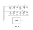
- FIG. 4 is a schematic diagrammatical representation of a controller and a plurality of engine cylinders of a single fuel spark ignited engine in accordance with certain embodiments of the present invention
- FIG. 5 is a table representative of a skip fire mode of an engine in accordance with an exemplary embodiment
- FIG. 6 is a table representative of a skip fire mode of an engine in accordance with another exemplary embodiment
- FIG. 7 is a table representative of a skip fire mode of an engine in accordance with yet another exemplary embodiment.
- FIG. 8 is a table representative of a skip fire mode of an engine in accordance with yet another exemplary embodiment.
- non-transitory computer-readable media is intended to be representative of any tangible computer-based device implemented in any method or technology for short-term and long-term storage of information, such as computer-readable instructions, data structures, program modules and sub-modules, or other data in any device. Therefore, the methods described herein may be encoded as executable instructions embodied in a tangible, non-transitory, computer readable medium, including, without limitation, a storage device and/or a memory device. Such instructions, when executed by a processor, cause the processor to perform at least a portion of the methods described herein.
- non-transitory computer-readable media includes all tangible, computer-readable media, including, without limitation, non-transitory computer storage devices, including, without limitation, volatile and nonvolatile media, and removable and non-removable media such as a firmware, physical and virtual storage, CD-ROMs, DVDs, and any other digital source such as a network or the internet, as well as yet to be developed digital means, with the sole exception being a transitory, propagating signal.
- the terms “software” and “firmware” are interchangeable, and may include any computer program stored in memory for execution by devices that include, without limitation, mobile devices, clusters, personal computers, workstations, clients, and servers.
- the term “computer” and related terms, e.g., “computing device”, are not limited to integrated circuits referred to in the art as a computer, but broadly refers to at least one microcontroller, microcomputer, programmable logic controller (PLC), application specific integrated circuit, and other programmable circuits, and these terms are used interchangeably herein.
- PLC programmable logic controller
- a method for operating an engine involves comparing a determined operating parameter with a predefined operating parameter.
- the method further involves controlling a fuel source and an ignition source so as to operate at least one engine cylinder in a skip fire mode for at least one cycle of a crank shaft when the determined operating parameter is greater than the predefined operating parameter.
- a system for controlling operation of an engine includes a controller coupled to a fuel injector of an engine. The controller is configured to compare a determined operating parameter with a predefined operating parameter.
- the controller is further configured to control a fuel source and an ignition source so as to operate at least one engine cylinder in a skip fire mode for at least one cycle of a crank shaft when the determined operating parameter is greater than the predefined operating parameter.
- the control involves transitioning the fuel source from a normal mode to the skip fire mode for the at least one cycle of the crank shaft either before transitioning the ignition source from the normal mode to the skip fire mode or when the ignition source is operated in the normal mode.
- a computer readable medium having instructions stored thereon which, when executed, causes a controller for an engine to perform an exemplary method, is disclosed.
- a system having an engine and a controller is disclosed. At least one cylinder of the engine is operated in a skip fire mode so that more power is is extracted from the remaining cylinders of the engine and exhaust emissions are reduced.
- FIG. 1 a schematic diagrammatical representation of a vehicle 10 moving from a first operating point to a second operating point along a predefined path is shown.
- the vehicle 10 is a locomotive. Suitable vehicles include passenger and non-passenger vehicles, hybrid vehicles, off-highway vehicles, on-road vehicles (such as tractor trailers), tracked vehicles, rail vehicles, and the like.
- the vehicle 10 includes an engine 12 and an exemplary control system 14 coupled to the engine 12 .
- the engine 12 and the control system 14 are mounted to a frame 11 provided with a plurality of wheels 13 .
- the vehicle 10 is driven by the engine 12 utilizing a plurality of fuels.
- a reduction in nitrogen oxide (NO x ) and particulate matter (PM) emissions is enabled by combusting a relatively larger fraction of the premixed fuel.
- NO x nitrogen oxide
- PM particulate matter
- relative costs and availability of different fuels are constantly in flux.
- diesel and natural gas may be utilized to drive the engine 12 . If the cost of diesel increases relative to the cost of the natural gas, more natural gas may be used resulting in reduced cost and emissions. If the cost of natural gas is increased relative to the cost of the diesel, then more diesel may be used to drive the engine 12 . It should be noted herein that in certain embodiments, the vehicle 10 may also utilize other fuels instead of diesel and natural gas.
- the exemplary control system 14 is used to control operation of the engine 12 and reduce exhaust emissions from the engine 12 .
- a dual fuel engine is discussed herein, the exemplary control system and an associated method may also be applicable to other types of engine, for example, a spark ignited single fuel engine.
- the engine may be a two stroke engine and in another embodiment, the engine may be a four stroke engine.
- the engine 12 and the control system 14 may be used for stationary applications. The engine 12 and the control system 14 are explained in greater detail with reference to subsequent figures.
- At least one cylinder of the engine 12 is operated in a skip fire mode so that more power is extracted from the remaining cylinders of the engine and exhaust emissions are reduced.
- Such an increased fueling reduces an air-to-fuel ratio for those cylinders that are fueled and allows the engine 12 to combust the fuel more efficiently.
- the resulting unburned hydrocarbons are significantly reduced.
- FIG. 2 a schematic diagrammatical representation of the engine 12 having emission control features is illustrated in accordance with certain embodiments of the present invention.
- embodiments of the present invention provide monitoring and control features, such as sensors and control logic in which at least one engine cylinder is operated in a skip fire mode and the remaining engine cylinders are fueled more, leading to a more efficient operation of the engine 12 .
- monitoring and control features such as sensors and control logic in which at least one engine cylinder is operated in a skip fire mode and the remaining engine cylinders are fueled more, leading to a more efficient operation of the engine 12 .
- Such an increased fueling of the remaining cylinders reduces an air-fuel ratio and allows the engine 12 to combust the fuel more efficiently. Hence generation of unburned hydrocarbons is significantly reduced.
- the engine 12 is a dual fuel engine.
- the illustrated engine 12 includes an air intake manifold 16 and an exhaust manifold 18 .
- the engine 12 is provided with a turbocharger 20 having a compressor 22 and a turbine 24 .
- the compressor 22 is operated to supply compressed air to the intake manifold 16 for combustion within a plurality of cylinders 26 .
- the turbine 24 is coupled to the exhaust manifold 18 , such that the exhaust gases expand through the turbine 24 , putting work onto and rotating a turbocharger shaft 28 coupled to the compressor 22 .
- the compressor 22 draws ambient air through a filter (not shown) and provides compressed air to a heat exchanger 30 . The temperature of air is increased due to compression through the compressor 20 .
- the compressed air flows through the heat exchanger 30 such that the temperature of air is reduced prior to delivery into the intake manifold 16 of the engine 12 .
- the heat exchanger 30 is an air-to-water heat exchanger, which utilizes a coolant to facilitate removal of heat from the compressed air.
- the heat exchanger 30 is an air-to-air heat exchanger, which utilizes ambient air to facilitate removal of heat from the compressed air.
- the heat exchanger 30 is a combination of an air-to-air heat exchanger and an air-to-water heat exchanger, which utilizes both ambient air and liquid to facilitate removal of heat from the compressed air.
- the control system 14 also includes a controller 32 .
- the controller 32 is an electronic logic controller that is programmable by a user.
- an operating parameter sensor 34 and an exhaust sensor 36 are used to measure an operating parameter and exhaust emissions respectively of the engine 12 .
- the controller 14 receives the corresponding output signals from the sensors 34 , 36 .
- other types of sensors for measuring different operating parameters associated with the engine 12 may be used.
- the operating parameter may be air-fuel ratio which is compared with a predefined air-fuel ratio.
- the controller 14 may estimate the air-fuel ratio based on the measured different parameters associated with the engine 12 .
- the air-fuel ratio may be determined based on information related to pressure, temperature, turbo speed, or the like of the engine 12 .
- the operating parameter may be at least one of engine power and engine speed which is compared with at least one of predefined power and predefined speed.
- a signal acquisition system 46 receives the plurality of signals from the plurality of sensors 34 , 36 and transmits the plurality of signals to the controller 32 .
- the controller 32 receives the determined operating parameter from the sensor 34 and the quantity of exhaust emissions from the sensor 36 via the signal acquisition system 46 .
- the controller 32 includes a database 48 , an analytic engine 50 , a processor 52 , and a memory 54 .
- the database 48 may be configured to store predefined information about the engine 12 .
- the database 48 may store information relating to air-fuel ratio, exhaust emissions, type of fuel, type of engine, engine speed, engine power, crank shaft rotation, or the like.
- the database 48 may be configured to store actual sensed/detected information from the above-mentioned sensors 34 , 36 .
- the algorithm facilitates the processing of signals from the above-mentioned plurality of sensors 34 , 36 .
- the database 48 may be stored in a single memory module at one location. In other embodiments, the database 48 may be stored in a plurality of memory modules in a distributed manner.
- the database 48 may be at least one of a SQL database, an Oracle database, and a MySQL database. In alternate embodiments, other types of databases including relationship database systems (RDBS) may be used to store the plurality of rules. It may be noted herein that in one embodiment, the database 48 is a customized database. In other embodiments, the database 48 may be an off-the-shelf database.
- the analytic engine 50 is communicatively coupled to the database 48 .
- the analytic engine 50 may be stored in the memory 54 and executable by the processor 52 .
- the analytic engine 50 may also be a specialized hardware such as a Field Programmable Gate Array (FPGA).
- the analytic engine 50 includes codes and routines configured to control the fuel injectors 38 , 40 , so as to operate at least one engine cylinder 26 in a skip fire mode for at least one cycle of a crank shaft 51 when the determined operating parameter is greater than a predefined operating parameter.
- the analytic engine 50 includes a set of instructions executable by the processor 52 .
- the analytic engine 50 is stored in the memory 54 and is accessible and executable by the processor 52 .
- the analytic engine 50 is adapted for communication and co-operation with the processor 52 and other modules of the controller 32 .
- the processor 52 is communicatively coupled to the database 48 and the analytic engine 50 .
- the processor 52 may include at least one arithmetic logic unit, microprocessor, general purpose controller or other processor arrays to perform the desired computations.
- the processor 52 is a custom hardware configured to perform functions of the analytic engine 50 and the signal acquisition system 46 .
- the processor 52 is a digital signal processor or a microcontroller.
- the processor 52 may also be configured to manage the contents of the database 48 . In some embodiments, other type of processors, operating systems, and physical configurations are envisioned.
- the memory 54 is coupled to the processor 52 and may also be optionally coupled to the other modules of the controller 32 .
- the memory 54 is configured to store instructions performed by the processor 52 and contents of the database 48 .
- the memory 54 may be a non-transitory storage medium.
- the memory 54 may be a dynamic random access memory (DRAM) device, a static random access memory (SRAM) device, flash memory, or other memory devices.
- DRAM dynamic random access memory
- SRAM static random access memory
- flash memory or other memory devices.
- the memory 54 may include a non-volatile memory or similar permanent storage device, and media such as a hard disk drive, a floppy disk drive, a compact disc read only memory (CD-ROM) device, a digital versatile disc read only memory (DVD-ROM) device, a digital versatile disc random access memory (DVD-RAM) device, a digital versatile disc rewritable (DVD-RW) device, a flash memory device, or other non-volatile storage devices.
- the memory 54 may be communicatively coupled to the processor 52 .
- the memory 54 is an on-board memory of the processor 52 .
- the non-transitory computer readable medium encoded with a program instructs the processor 52 to perform functions associated with the controller 32 for controlling operation of the engine 12 .
- the program instructions include one or more functions of the database 48 , the analytic engine 50 , and the signal acquisition system 46 .
- a plurality of first and second fuel injectors 38 , 40 are used for injecting a plurality of fuels (for example, a first fuel 42 and a second fuel 44 respectively) into the plurality of cylinders 26 of the engine 12 .
- the first fuel 42 may be a liquid fuel and the second fuel 44 may be a gaseous fuel.
- the gaseous fuel may be natural gas and the liquid fuel may be diesel.
- the first fuel injectors 38 is used to inject the first fuel 42 into the plurality of cylinders 26 of the engine 12 .
- the second fuel injectors 40 inject the second fuel 44 into the intake manifold 16 of the engine 12 .
- the plurality of first fuel injectors 38 constitutes an ignition source and the plurality of second fuel injectors 40 constitutes a fuel source.
- control valves may be provided to control injection of the plurality of fuels 42 , 44 into the plurality of cylinders 26 .
- first fuel liquid fuel
- second fuel gaseous fuel
- natural gas may be used interchangeably.
- a piston (not shown) is slidably disposed in each cylinder 26 and reciprocates between a top dead center and a bottom dead center position.
- the controller 32 is operable to produce a control signal to control the plurality of first and second fuel injectors 38 , 40 , receive corresponding output signals from the sensors 34 , 36 , and control operation of the engine 12 .
- the controller 32 controls the plurality of first fuel injectors 38 for injecting the first fuel 42 and one fuel injector from the plurality of second fuel injectors 40 for skipping injection of the second fuel 44 for the at least one cycle of the crank shaft 51 when the determined operating parameter is greater than the predefined operating parameter.
- One or more cylinders from the plurality of the cylinders 26 may be operated in a skip fire mode.
- one cylinder 26 may be operated in-turn in a skip fire mode for each cycle of the crank shaft 51 . For example, if there are six cylinders, cylinder 1 may be operated in a skip fire mode for one cycle of the crank shaft 51 . Thereafter, cylinder 2 may be operated in a skip fire mode for another cycle of the crank shaft 51 .
- the skip fire mode may be repeated for each cylinder.
- the order of the cylinders and cycles of the crank shaft 51 for operating in a skip fire mode may vary depending on the application. Various patterns of skip fire mode are envisioned in order to maintain all the cylinders 26 warm and also to maintain good mechanical balance of the engine 12 .
- the controller 32 controls one fuel injector from the plurality of first fuel injectors 38 for skipping injection of the first fuel 42 and one fuel injector from the plurality of second fuel injectors 40 for skipping injection of the second fuel 44 for another cycle after the at least one cycle of the crank shaft 51 , when the determined operating parameter is greater than the predefined operating parameter. In yet another instance, the controller 32 controls one fuel injector from the plurality of first fuel injectors 38 for skipping injection of the first fuel 42 and one fuel injector from the plurality of second fuel injectors 40 for skipping injection of the second fuel 44 for subsequent alternate cycles after the at least one cycle of the crank shaft 51 , when the determined operating parameter is greater than the predefined operating parameter.
- the controller 32 controls the plurality of first fuel injectors 38 for injecting the first fuel 42 and the plurality of second fuel injectors 40 for skipping injection of the second fuel 44 for alternate cycles of the crank shaft 51 , when the determined operating parameter is greater than the predefined operating parameter.
- FIG. 4 is a detailed schematic representation of the controller 32 and the plurality of cylinders 26 .
- the engine 12 does not have the fuel injectors 38 (shown in FIG. 3 ) but has only the fuel injectors 40 for injecting the fuel 44 , for example gaseous fuel.
- the engine 12 has a plurality of spark plugs 49 for igniting a spark for combustion of the fuel 44 .
- the plurality of fuel injectors 40 constitutes a fuel source and the plurality of spark plugs 49 constitutes an ignition source.
- the controller 32 controls the spark plugs 49 for triggering a spark and one fuel injector from the plurality of fuel injectors 40 for skipping injection of the fuel 44 for the at least one cycle of the crank shaft 51 when the determined operating parameter is greater than the predefined operating parameter.
- the controller 32 controls one spark plug from the plurality of spark plugs 49 for skipping trigger of the spark and one fuel injector from the plurality of fuel injectors 40 for skipping injection of the fuel 44 for another cycle after the at least one cycle of the crank shaft 51 , when the determined operating parameter is greater than the predefined operating parameter. In yet another instance, the controller 32 controls one spark plug from the plurality of spark plugs 49 for skipping trigger of the spark and one fuel injector from the plurality of fuel injectors 40 for skipping injection of the fuel 44 for subsequent alternate cycles after the at least one cycle of the crank shaft 51 , when the determined operating parameter is greater than the predefined operating parameter.
- the controller 32 controls the spark plugs 49 for triggering the spark and one fuel injector from the plurality of fuel injectors 40 for skipping injection of the fuel 44 for alternate cycles of the crank shaft 51 , when the determined operating parameter is greater than the predefined operating parameter.
- FIG. 5 shows a table 56 representative of a skip fire mode of an engine in accordance with an exemplary embodiment.
- the table 56 has a column 58 indicative of a number of consecutive cycles of a crank shaft, a column 60 representative of a status as to whether diesel is fired into a plurality of cylinders, a column 62 representative of a status as to whether a gaseous fuel is fired into the plurality of cylinders, a column 64 representative of a status as to whether a skip fire mode is activated. For each cycle, status of firing of fuel/activation of skip fire mode is indicated by either a “Yes” or “No”. In the illustrated embodiment, the column 58 shows 25 cycles of the crank shaft.
- the delay in initiation of the skip fire for at least one more cycle of the crank shaft is done to overcome the associated problems during the transition from the normal mode to the skip fire mode.
- column 64 is indicative of the activation of the skip fire mode. Specifically, for cycles 11 and 12 , diesel is fired into the plurality of cylinders and the gaseous fuel is not fired (skip fire) to one cylinder. For cycles 13 - 25 of the crank shaft, column 64 is indicative of activation of the skip fire mode. Specifically, for cycles 13 - 25 , both diesel and the gaseous fuel are not fired to one cylinder.
- the column 60 is representative of a status as to whether spark is triggered.
- column 64 is indicative of the activation of skip fire mode. However, spark is triggered and the gaseous fuel is fired into the plurality of cylinders.
- column 64 is indicative of the activation of the skip fire mode. Specifically, for cycles 11 and 12 , the spark is triggered to the plurality of cylinders and the gaseous fuel is not fired (skip fire) to one cylinder.
- columns 13 - 25 of the crank shaft column 64 is indicative of activation of the skip fire mode. Specifically, for cycles 13 - 25 , the spark is not triggered and the gaseous fuel is not fired, to one cylinder.
- FIG. 6 shows a table 66 representative of a skip fire mode of a dual fuel engine in accordance with another exemplary embodiment.
- the table 66 has a column 68 indicative of a number of consecutive cycles of a crank shaft, a column 70 representative of a status as to whether diesel is fired into a plurality of cylinders, a column 72 representative of a status as to whether a gaseous fuel is fired into the plurality of cylinders, a column 74 representative of a status as to whether a skip fire mode is activated. For each cycle, status of firing of fuel/activation of skip fire mode is indicated by either a “Yes” or “No”. In the illustrated embodiment, the column 74 shows 25 cycles of the crank shaft.
- the engine for cycles 1 - 9 of the crank shaft, the engine is not operated in a skip fire mode.
- column 74 is indicative of the activation of the skip fire mode.
- diesel and the gaseous fuel are fired into the plurality of cylinders.
- column 74 is indicative of the activation of the skip fire mode. Specifically, for cycles 11 - 25 , diesel is fired into the plurality of cylinders and the gaseous fuel is not fired (skip fire) to one cylinder.
- the column 70 is representative of a status as to whether spark is triggered.
- column 74 is indicative of the activation of the skip fire mode. However, spark is triggered and the gaseous fuel is fired into the plurality of cylinders.
- column 74 is indicative of the activation of the skip fire mode. Specifically, for cycles 11 - 25 , the spark is triggered to the plurality of cylinders and the gaseous fuel is not fired (skip fire) to one cylinder.
- FIG. 7 shows a table 76 representative of a skip fire mode of a dual fuel engine in accordance with another exemplary embodiment.
- the table 76 has a column 78 indicative of a number of consecutive cycles of a crank shaft, a column 80 representative of a status as to whether diesel is fired into a plurality of cylinders, a column 82 representative of a status as to whether a gaseous fuel is fired into the plurality of cylinders, a column 84 representative of a status as to whether a skip fire mode is activated.
- status of firing of fuel/activation of skip fire mode is indicated by either a “Yes” or “No”.
- the column 84 shows 25 cycles of the crank shaft.
- the engine for cycles 1 - 9 of the crank shaft, the engine is not operated in a skip fire mode.
- column 84 is indicative of the activation of the skip fire mode.
- both diesel and the gaseous fuel are fired into the plurality of cylinders.
- column 84 is indicative of the activation skip fire mode.
- diesel is fired into the plurality of cylinders and the gaseous fuel is not fired (skip fire) to one cylinder.
- both diesel and the gaseous fuel are not fired into one cylinder.
- the column 80 is representative of a status as to whether spark is triggered.
- column 84 is indicative of the activation of the skip fire mode.
- spark is triggered and the gaseous fuel is fired into the plurality of cylinders.
- column 84 is indicative of the activation skip fire mode.
- spark is triggered to the plurality of cylinders and the gaseous fuel is not fired (skip fire) to one cylinder.
- spark is not triggered and the gaseous fuel is not fired, into one cylinder.
- FIG. 8 shows a table 86 representative of a skip fire mode of a dual fuel engine in accordance with another exemplary embodiment.
- the table 86 has a column 88 indicative of a number of consecutive cycles of a crank shaft, a column 90 representative of a status as to whether diesel is fired into a plurality of cylinders, a column 92 representative of a status as to whether a gaseous fuel is fired into the plurality of cylinders, a column 94 representative of a status as to whether a skip fire mode is activated.
- status of firing of fuel/activation of skip fire mode is indicated by either a “Yes” or “No”.
- the column 94 shows 25 cycles of the crank shaft.
- the engine for cycles 1 - 9 of the crank shaft, the engine is not operated in a skip fire mode.
- column 94 is indicative of the activation of the skip fire mode.
- both diesel and the gaseous fuel are fired into the plurality of cylinders.
- column 94 is indicative of the activation skip fire mode.
- diesel is fired into the plurality of cylinders and the gaseous fuel is not fired (skip fire) to one cylinder.
- skip fire gaseous fuel
- the column 90 is representative of a status as to whether spark is triggered.
- column 94 is indicative of the activation of the skip fire mode.
- spark is triggered and the gaseous fuel is fired into the plurality of cylinders.
- column 94 is indicative of the activation skip fire mode. Specifically, for cycles 11 , 13 , 15 , 17 , 19 , 21 , 23 , and 25 , spark is triggered to the plurality of cylinders and the gaseous fuel is not fired (skip fire) to one cylinder.
- operating an engine in a skip fire mode allows the engine to run at a lower power in a dual fuel mode. Hence, the amount of diesel needed for operation and emissions are reduced, and fuel efficiency is enhanced. The transition to and from skip fire operation is controlled so that misfire events are prevented.
Landscapes
- Engineering & Computer Science (AREA)
- Chemical & Material Sciences (AREA)
- Combustion & Propulsion (AREA)
- Mechanical Engineering (AREA)
- General Engineering & Computer Science (AREA)
- Oil, Petroleum & Natural Gas (AREA)
- Computer Hardware Design (AREA)
- Microelectronics & Electronic Packaging (AREA)
- Electrical Control Of Air Or Fuel Supplied To Internal-Combustion Engine (AREA)
- Combined Controls Of Internal Combustion Engines (AREA)
- Output Control And Ontrol Of Special Type Engine (AREA)
Abstract
Description
Claims (18)
Priority Applications (4)
| Application Number | Priority Date | Filing Date | Title |
|---|---|---|---|
| US14/450,493 US9631569B2 (en) | 2014-08-04 | 2014-08-04 | System and method for controlling operation of an engine |
| DE102015112009.7A DE102015112009A1 (en) | 2014-08-04 | 2015-07-23 | System and method for controlling the operation of an engine |
| US15/132,013 US10030617B2 (en) | 2011-05-23 | 2016-04-18 | Systems and methods for engine control |
| US16/023,202 US10655571B2 (en) | 2011-05-23 | 2018-06-29 | Systems and methods for engine control |
Applications Claiming Priority (1)
| Application Number | Priority Date | Filing Date | Title |
|---|---|---|---|
| US14/450,493 US9631569B2 (en) | 2014-08-04 | 2014-08-04 | System and method for controlling operation of an engine |
Related Child Applications (2)
| Application Number | Title | Priority Date | Filing Date |
|---|---|---|---|
| US13/562,356 Continuation-In-Part US8985088B2 (en) | 2011-05-23 | 2012-07-31 | Systems and methods for controlling exhaust gas recirculation |
| US15/132,013 Continuation-In-Part US10030617B2 (en) | 2011-05-23 | 2016-04-18 | Systems and methods for engine control |
Publications (2)
| Publication Number | Publication Date |
|---|---|
| US20160032859A1 US20160032859A1 (en) | 2016-02-04 |
| US9631569B2 true US9631569B2 (en) | 2017-04-25 |
Family
ID=55079698
Family Applications (1)
| Application Number | Title | Priority Date | Filing Date |
|---|---|---|---|
| US14/450,493 Active 2035-05-12 US9631569B2 (en) | 2011-05-23 | 2014-08-04 | System and method for controlling operation of an engine |
Country Status (2)
| Country | Link |
|---|---|
| US (1) | US9631569B2 (en) |
| DE (1) | DE102015112009A1 (en) |
Cited By (1)
| Publication number | Priority date | Publication date | Assignee | Title |
|---|---|---|---|---|
| EP3726036A1 (en) | 2019-04-15 | 2020-10-21 | Winterthur Gas & Diesel AG | Large motor and method for operating a large motor |
Families Citing this family (5)
| Publication number | Priority date | Publication date | Assignee | Title |
|---|---|---|---|---|
| CA2798599C (en) * | 2012-12-14 | 2013-11-12 | Westport Power Inc. | Skip-fire fuel injection system and method |
| US10066590B2 (en) | 2015-02-27 | 2018-09-04 | Avl Powertrain Engineering, Inc. | Opposed piston three nozzle combustion chamber design |
| US10161371B2 (en) | 2015-02-27 | 2018-12-25 | Avl Powertrain Engineering, Inc. | Opposed piston three nozzle piston bowl design |
| EP3282111B1 (en) * | 2016-08-11 | 2020-07-01 | Caterpillar Motoren GmbH & Co. KG | Method for starting a gaseous fuel combustion engine |
| US11821375B2 (en) * | 2021-12-06 | 2023-11-21 | Transportation Ip Holdings, Llc | Methods and systems for skip fire in a multi fuel engine |
Citations (75)
| Publication number | Priority date | Publication date | Assignee | Title |
|---|---|---|---|---|
| US4143635A (en) | 1976-12-08 | 1979-03-13 | Nissan Motor Company, Limited | Exhaust gas recirculated engine with variable cylinder disablement control |
| US4179892A (en) | 1977-12-27 | 1979-12-25 | Cummins Engine Company, Inc. | Internal combustion engine with exhaust gas recirculation |
| US4231338A (en) | 1978-12-28 | 1980-11-04 | Nissan Motor Company, Limited | Internal combustion engine |
| US4462351A (en) | 1982-02-25 | 1984-07-31 | Nissan Motor Company, Limited | Split type internal combustion engine |
| US4955326A (en) | 1989-04-12 | 1990-09-11 | Cooper Industries, Inc. | Low emission dual fuel engine and method of operating same |
| US5377631A (en) | 1993-09-20 | 1995-01-03 | Ford Motor Company | Skip-cycle strategies for four cycle engine |
| US5477830A (en) | 1993-12-30 | 1995-12-26 | Servojet Products International | Electronic fuel injection system for internal combustion engines having a common intake port for each pair of cylinders |
| US5517976A (en) | 1993-07-20 | 1996-05-21 | Mtu Motoren- Und Turbinen-Union Friedrichshafen Gmbh | Diesel engine equipped for reducing harmful substances in its operation |
| US5553575A (en) | 1995-06-16 | 1996-09-10 | Servojet Products International | Lambda control by skip fire of unthrottled gas fueled engines |
| US5561602A (en) | 1994-07-01 | 1996-10-01 | General Electric Company | Tunnel operation for self-propelled traction vehicles |
| US5826563A (en) * | 1997-07-28 | 1998-10-27 | General Electric Company | Diesel engine cylinder skip firing system |
| US6006732A (en) | 1998-09-03 | 1999-12-28 | Navistar International Transportation Corp | Balanced flow EGR control apparatus |
| DE19838725A1 (en) | 1998-08-26 | 2000-03-02 | Mtu Friedrichshafen Gmbh | Multi-cylinder internal combustion engine and method for operating such |
| US6138650A (en) | 1999-04-06 | 2000-10-31 | Caterpillar Inc. | Method of controlling fuel injectors for improved exhaust gas recirculation |
| US6286489B1 (en) | 1998-12-11 | 2001-09-11 | Caterpillar Inc. | System and method of controlling exhaust gas recirculation |
| EP1146220A1 (en) | 2000-04-12 | 2001-10-17 | Masanori Kondo | Method for reducing particulates emissions from a diesel engine |
| US6360724B1 (en) | 2000-05-18 | 2002-03-26 | Brunswick Corporation | Method and apparatus for controlling the power output of a homogenous charge internal combustion engine |
| US6405705B1 (en) | 2000-05-19 | 2002-06-18 | General Electric Company | Method and apparatus for reducing locomotive diesel engine smoke using skip firing |
| US6408625B1 (en) | 1999-01-21 | 2002-06-25 | Cummins Engine Company, Inc. | Operating techniques for internal combustion engines |
| US6543230B1 (en) | 1999-08-05 | 2003-04-08 | Daimlerchrysler Ag | Method for adjusting a boosted internal combustion engine with exhaust gas recirculation |
| US20030172900A1 (en) * | 2002-03-12 | 2003-09-18 | Ford Global Technologies, Inc. | Strategy and control system for deactivation and reactivation of cylinders of a variable displacement engine |
| US20040139944A1 (en) | 2003-01-06 | 2004-07-22 | Hitachi, Ltd. | Method and device for controlling fuel injection in the bi-fuel internal combustion engine |
| US20040177605A1 (en) | 2002-02-26 | 2004-09-16 | Daisuke Kojima | Control device and control method for internal combustion engine |
| US20040194463A1 (en) | 2003-04-03 | 2004-10-07 | Isuzu Motors Limited | Turbo-charged engine with EGR |
| US6871642B1 (en) | 2004-02-27 | 2005-03-29 | Daimlerchrysler Ag | Internal combustion engine with an exhaust gas turbocharger and an exhaust gas recirculation device and method of operating same |
| US6877492B1 (en) | 2004-02-27 | 2005-04-12 | Daimlerchrysler Ag | Internal combustion engine with an exhaust gas turbocharger and an exhaust gas recirculation device and method of operating same |
| US6948475B1 (en) | 2002-11-12 | 2005-09-27 | Clean Air Power, Inc. | Optimized combustion control of an internal combustion engine equipped with exhaust gas recirculation |
| US6953030B2 (en) | 2001-05-21 | 2005-10-11 | Scania Cv Ab (Publ) | Method for fuel injection in a combustion engine and combustion engine |
| US7270089B2 (en) * | 2003-06-11 | 2007-09-18 | Clean Air Power, Inc. | Method and apparatus for controlling transition between operating modes in a multimode engine |
| US7444815B2 (en) | 2005-12-09 | 2008-11-04 | Deere & Company | EGR system for high EGR rates |
| US7487766B2 (en) | 2007-04-23 | 2009-02-10 | Southwest Research Institute | Flexible fuel engines with exhaust gas recirculation for improved engine efficiency |
| US20090241918A1 (en) | 2008-04-01 | 2009-10-01 | Toyota Jidosha Kabushiki Kaisha | Engine control device and engine control method |
| US7640094B2 (en) | 2004-10-01 | 2009-12-29 | Isuzu Motors Limited | Diesel engine |
| US20100043762A1 (en) | 2007-01-25 | 2010-02-25 | Frank Weiss | Method for controlling the exhaust gas recirculation of an internal combustion engine |
| US20100100299A1 (en) | 2008-07-11 | 2010-04-22 | Tripathi Adya S | System and Methods for Improving Efficiency in Internal Combustion Engines |
| US20100211294A1 (en) | 2007-09-12 | 2010-08-19 | Toyota Jidosha Kabushiki Kaisha | Control device for internal combustion engine |
| US7801664B2 (en) | 2007-07-12 | 2010-09-21 | Ford Global Technologies, Llc | Cylinder charge temperature control for an internal combustion engine |
| US7849835B2 (en) | 2008-07-11 | 2010-12-14 | Tula Technology, Inc. | Internal combustion engine control for improved fuel efficiency |
| US20110023829A1 (en) | 2008-04-14 | 2011-02-03 | Toyota Jidosha Kabushiki Kaisha | Control system and control method for internal combustion engine |
| US20110030657A1 (en) | 2009-07-10 | 2011-02-10 | Tula Technology, Inc. | Skip fire engine control |
| WO2011017272A1 (en) | 2009-08-01 | 2011-02-10 | Electro-Motive Diesel, Inc. | Exhaust gas recirculation system and apparatus for a locomotive two-stroke uniflow scavenged diesel engine |
| US20110030662A1 (en) | 2009-08-07 | 2011-02-10 | Zitzler Guenter | Gas guide system for a combustion engine, a combustion engine and a method for operating the engine |
| US20110048372A1 (en) | 2008-07-11 | 2011-03-03 | Dibble Robert W | System and Methods for Stoichiometric Compression Ignition Engine Control |
| US7941999B2 (en) | 2007-03-09 | 2011-05-17 | Mtu Friedrichshafen Gmbh | Internal combustion engine |
| US20110220068A1 (en) * | 2010-03-10 | 2011-09-15 | Gm Global Technology Operations, Inc. | Fuel management systems and methods for variable displacement engines |
| US20110253113A1 (en) | 2008-07-31 | 2011-10-20 | General Electric Company | Methods and systems for operating an engine |
| US20110265454A1 (en) | 2011-05-12 | 2011-11-03 | Ford Global Technologies, Llc | Methods and Systems for Variable Displacement Engine Control |
| US20110283682A1 (en) | 2007-08-14 | 2011-11-24 | Shawn Michael Gallagher | System and method for regenerating a particulate filter |
| US20110307127A1 (en) | 2010-06-15 | 2011-12-15 | Kendall Roger Swenson | Method and system for controlling engine performance |
| US8113186B2 (en) | 2007-02-19 | 2012-02-14 | Toyota Jidosha Kabushiki Kaisha | Multifuel internal combustion engine |
| US20120042633A1 (en) * | 2010-08-20 | 2012-02-23 | Silvestri Chester J | System and Methods for Skip Fire Engine with a Lean NOx Trap |
| US20120046853A1 (en) | 2010-08-20 | 2012-02-23 | Silvestri Chester J | System and Methods for Improved Efficiency Compression Ignition Internal Combustion Engine Control |
| US20120055444A1 (en) | 2010-09-07 | 2012-03-08 | Ford Global Technologies, Llc | Multi-cylinder internal combustion engine and method for operating a multi-cylinder internal combustion engine |
| US20120078492A1 (en) | 2010-09-23 | 2012-03-29 | General Electric Company | Engine system and method |
| US8205583B2 (en) | 2007-07-12 | 2012-06-26 | Ford Global Technologies, Llc | Cylinder charge temperature control for an internal combustion engine |
| US20120216530A1 (en) | 2011-02-24 | 2012-08-30 | Paul Lloyd Flynn | Systems and methods for exhaust gas recirculation |
| US8291891B2 (en) | 2008-06-17 | 2012-10-23 | Southwest Research Institute | EGR system with dedicated EGR cylinders |
| US8316829B2 (en) | 2008-02-08 | 2012-11-27 | Cummins Ip, Inc. | Apparatus, system, and method for efficiently operating an internal combustion engine utilizing exhaust gas recirculation |
| US20120298070A1 (en) | 2011-05-23 | 2012-11-29 | Omowoleola Chukuwuemeka Akinyemi | Method for exhaust gas recirculation rate control |
| US20120323465A1 (en) | 2011-06-17 | 2012-12-20 | General Electric Company | Methods and systems for exhaust gas recirculation cooler regeneration |
| US20120323470A1 (en) | 2011-06-17 | 2012-12-20 | Adam Klingbeil | Methods and systems for exhaust gas recirculation cooler regeneration |
| US20130024086A1 (en) | 2011-07-20 | 2013-01-24 | Luke Henry | Method and system for controlling an engine during tunneling operation |
| CA2798599A1 (en) | 2012-12-14 | 2013-02-08 | Westport Power Inc. | Skip-fire fuel injection system and method |
| WO2013029760A1 (en) | 2011-08-26 | 2013-03-07 | Caterpillar Motoren Gmbh & Co. Kg | Pilot injection of dual fuel engines |
| US20130144512A1 (en) * | 2010-07-01 | 2013-06-06 | Orbital Australia Pty Limited | Method of injecting fuel into an engine |
| WO2013112173A1 (en) | 2012-01-27 | 2013-08-01 | International Engine Intellectual Property Company, Llc | Multi-fuel engine with variable valve timing |
| US8566006B2 (en) | 2008-01-24 | 2013-10-22 | Mack Trucks, Inc. | Method for controlling combustion in a multi-cylinder engine, and multi-cylinder engine |
| US20140034014A1 (en) | 2012-07-31 | 2014-02-06 | Neil Xavier Blythe | Systems and methods for controlling exhaust gas recirculation |
| US8733081B2 (en) | 2010-04-12 | 2014-05-27 | Toyota Jidosha Kabushiki Kaisha | Control apparatus for internal combustion engine |
| US20140261309A1 (en) * | 2013-03-15 | 2014-09-18 | Tula Technology Inc. | Engine diagnostics with skip fire control |
| US8915081B2 (en) | 2011-04-13 | 2014-12-23 | GM Global Technology Operations LLC | Internal combustion engine |
| US8931462B2 (en) | 2010-02-25 | 2015-01-13 | Man Truck & Bus Ag | EGR system for an internal combustion engine that feeds exhaust gas independent of intake air |
| US20150033699A1 (en) * | 2012-03-23 | 2015-02-05 | Snecma | Ignition unit for turbojet engine |
| US20150159578A1 (en) * | 2013-12-05 | 2015-06-11 | Ford Global Technologies, Llc | Method of diagnosing injector variability in a multiple injector system |
| US20150354482A1 (en) | 2014-06-05 | 2015-12-10 | Ford Global Technologies, Llc | Systems and methods for dedicated egr cylinder valve control |
-
2014
- 2014-08-04 US US14/450,493 patent/US9631569B2/en active Active
-
2015
- 2015-07-23 DE DE102015112009.7A patent/DE102015112009A1/en active Pending
Patent Citations (78)
| Publication number | Priority date | Publication date | Assignee | Title |
|---|---|---|---|---|
| US4143635A (en) | 1976-12-08 | 1979-03-13 | Nissan Motor Company, Limited | Exhaust gas recirculated engine with variable cylinder disablement control |
| US4179892A (en) | 1977-12-27 | 1979-12-25 | Cummins Engine Company, Inc. | Internal combustion engine with exhaust gas recirculation |
| US4231338A (en) | 1978-12-28 | 1980-11-04 | Nissan Motor Company, Limited | Internal combustion engine |
| US4462351A (en) | 1982-02-25 | 1984-07-31 | Nissan Motor Company, Limited | Split type internal combustion engine |
| US4955326A (en) | 1989-04-12 | 1990-09-11 | Cooper Industries, Inc. | Low emission dual fuel engine and method of operating same |
| US5517976A (en) | 1993-07-20 | 1996-05-21 | Mtu Motoren- Und Turbinen-Union Friedrichshafen Gmbh | Diesel engine equipped for reducing harmful substances in its operation |
| US5377631A (en) | 1993-09-20 | 1995-01-03 | Ford Motor Company | Skip-cycle strategies for four cycle engine |
| US5477830A (en) | 1993-12-30 | 1995-12-26 | Servojet Products International | Electronic fuel injection system for internal combustion engines having a common intake port for each pair of cylinders |
| US5561602A (en) | 1994-07-01 | 1996-10-01 | General Electric Company | Tunnel operation for self-propelled traction vehicles |
| US5553575A (en) | 1995-06-16 | 1996-09-10 | Servojet Products International | Lambda control by skip fire of unthrottled gas fueled engines |
| US5826563A (en) * | 1997-07-28 | 1998-10-27 | General Electric Company | Diesel engine cylinder skip firing system |
| DE19838725A1 (en) | 1998-08-26 | 2000-03-02 | Mtu Friedrichshafen Gmbh | Multi-cylinder internal combustion engine and method for operating such |
| US6789531B1 (en) | 1998-08-26 | 2004-09-14 | Mtu Friedrichshafen Gmbh | Multiple-cylinder internal combustion engine and a method for operating the same |
| US6006732A (en) | 1998-09-03 | 1999-12-28 | Navistar International Transportation Corp | Balanced flow EGR control apparatus |
| US6286489B1 (en) | 1998-12-11 | 2001-09-11 | Caterpillar Inc. | System and method of controlling exhaust gas recirculation |
| US6408625B1 (en) | 1999-01-21 | 2002-06-25 | Cummins Engine Company, Inc. | Operating techniques for internal combustion engines |
| US6138650A (en) | 1999-04-06 | 2000-10-31 | Caterpillar Inc. | Method of controlling fuel injectors for improved exhaust gas recirculation |
| US6543230B1 (en) | 1999-08-05 | 2003-04-08 | Daimlerchrysler Ag | Method for adjusting a boosted internal combustion engine with exhaust gas recirculation |
| EP1146220A1 (en) | 2000-04-12 | 2001-10-17 | Masanori Kondo | Method for reducing particulates emissions from a diesel engine |
| US6360724B1 (en) | 2000-05-18 | 2002-03-26 | Brunswick Corporation | Method and apparatus for controlling the power output of a homogenous charge internal combustion engine |
| US6405705B1 (en) | 2000-05-19 | 2002-06-18 | General Electric Company | Method and apparatus for reducing locomotive diesel engine smoke using skip firing |
| US6953030B2 (en) | 2001-05-21 | 2005-10-11 | Scania Cv Ab (Publ) | Method for fuel injection in a combustion engine and combustion engine |
| US20040177605A1 (en) | 2002-02-26 | 2004-09-16 | Daisuke Kojima | Control device and control method for internal combustion engine |
| US20030172900A1 (en) * | 2002-03-12 | 2003-09-18 | Ford Global Technologies, Inc. | Strategy and control system for deactivation and reactivation of cylinders of a variable displacement engine |
| US6948475B1 (en) | 2002-11-12 | 2005-09-27 | Clean Air Power, Inc. | Optimized combustion control of an internal combustion engine equipped with exhaust gas recirculation |
| US20040139944A1 (en) | 2003-01-06 | 2004-07-22 | Hitachi, Ltd. | Method and device for controlling fuel injection in the bi-fuel internal combustion engine |
| CN1536215A (en) | 2003-04-03 | 2004-10-13 | 五十铃自动车株式会社 | Exhaust supercharged engine with EGR |
| US20040194463A1 (en) | 2003-04-03 | 2004-10-07 | Isuzu Motors Limited | Turbo-charged engine with EGR |
| US7270089B2 (en) * | 2003-06-11 | 2007-09-18 | Clean Air Power, Inc. | Method and apparatus for controlling transition between operating modes in a multimode engine |
| US6871642B1 (en) | 2004-02-27 | 2005-03-29 | Daimlerchrysler Ag | Internal combustion engine with an exhaust gas turbocharger and an exhaust gas recirculation device and method of operating same |
| US6877492B1 (en) | 2004-02-27 | 2005-04-12 | Daimlerchrysler Ag | Internal combustion engine with an exhaust gas turbocharger and an exhaust gas recirculation device and method of operating same |
| US7640094B2 (en) | 2004-10-01 | 2009-12-29 | Isuzu Motors Limited | Diesel engine |
| US7444815B2 (en) | 2005-12-09 | 2008-11-04 | Deere & Company | EGR system for high EGR rates |
| US20100043762A1 (en) | 2007-01-25 | 2010-02-25 | Frank Weiss | Method for controlling the exhaust gas recirculation of an internal combustion engine |
| US8113186B2 (en) | 2007-02-19 | 2012-02-14 | Toyota Jidosha Kabushiki Kaisha | Multifuel internal combustion engine |
| US7941999B2 (en) | 2007-03-09 | 2011-05-17 | Mtu Friedrichshafen Gmbh | Internal combustion engine |
| US7487766B2 (en) | 2007-04-23 | 2009-02-10 | Southwest Research Institute | Flexible fuel engines with exhaust gas recirculation for improved engine efficiency |
| US8205583B2 (en) | 2007-07-12 | 2012-06-26 | Ford Global Technologies, Llc | Cylinder charge temperature control for an internal combustion engine |
| US7801664B2 (en) | 2007-07-12 | 2010-09-21 | Ford Global Technologies, Llc | Cylinder charge temperature control for an internal combustion engine |
| US20110283682A1 (en) | 2007-08-14 | 2011-11-24 | Shawn Michael Gallagher | System and method for regenerating a particulate filter |
| US20100211294A1 (en) | 2007-09-12 | 2010-08-19 | Toyota Jidosha Kabushiki Kaisha | Control device for internal combustion engine |
| US8566006B2 (en) | 2008-01-24 | 2013-10-22 | Mack Trucks, Inc. | Method for controlling combustion in a multi-cylinder engine, and multi-cylinder engine |
| US8316829B2 (en) | 2008-02-08 | 2012-11-27 | Cummins Ip, Inc. | Apparatus, system, and method for efficiently operating an internal combustion engine utilizing exhaust gas recirculation |
| US20090241918A1 (en) | 2008-04-01 | 2009-10-01 | Toyota Jidosha Kabushiki Kaisha | Engine control device and engine control method |
| US20110023829A1 (en) | 2008-04-14 | 2011-02-03 | Toyota Jidosha Kabushiki Kaisha | Control system and control method for internal combustion engine |
| US8291891B2 (en) | 2008-06-17 | 2012-10-23 | Southwest Research Institute | EGR system with dedicated EGR cylinders |
| US7849835B2 (en) | 2008-07-11 | 2010-12-14 | Tula Technology, Inc. | Internal combustion engine control for improved fuel efficiency |
| US20100100299A1 (en) | 2008-07-11 | 2010-04-22 | Tripathi Adya S | System and Methods for Improving Efficiency in Internal Combustion Engines |
| US20110048372A1 (en) | 2008-07-11 | 2011-03-03 | Dibble Robert W | System and Methods for Stoichiometric Compression Ignition Engine Control |
| US20110253113A1 (en) | 2008-07-31 | 2011-10-20 | General Electric Company | Methods and systems for operating an engine |
| US20110030657A1 (en) | 2009-07-10 | 2011-02-10 | Tula Technology, Inc. | Skip fire engine control |
| WO2011017272A1 (en) | 2009-08-01 | 2011-02-10 | Electro-Motive Diesel, Inc. | Exhaust gas recirculation system and apparatus for a locomotive two-stroke uniflow scavenged diesel engine |
| CN101994580A (en) | 2009-08-07 | 2011-03-30 | Mtu腓特烈港有限责任公司 | Gas guide system for peripheral device of internal combustion engine, internal combustion engine and a method for operating the engine |
| US20110030662A1 (en) | 2009-08-07 | 2011-02-10 | Zitzler Guenter | Gas guide system for a combustion engine, a combustion engine and a method for operating the engine |
| US8931462B2 (en) | 2010-02-25 | 2015-01-13 | Man Truck & Bus Ag | EGR system for an internal combustion engine that feeds exhaust gas independent of intake air |
| US20110220068A1 (en) * | 2010-03-10 | 2011-09-15 | Gm Global Technology Operations, Inc. | Fuel management systems and methods for variable displacement engines |
| US8733081B2 (en) | 2010-04-12 | 2014-05-27 | Toyota Jidosha Kabushiki Kaisha | Control apparatus for internal combustion engine |
| US20110307127A1 (en) | 2010-06-15 | 2011-12-15 | Kendall Roger Swenson | Method and system for controlling engine performance |
| US20130144512A1 (en) * | 2010-07-01 | 2013-06-06 | Orbital Australia Pty Limited | Method of injecting fuel into an engine |
| US20120046853A1 (en) | 2010-08-20 | 2012-02-23 | Silvestri Chester J | System and Methods for Improved Efficiency Compression Ignition Internal Combustion Engine Control |
| US20120042633A1 (en) * | 2010-08-20 | 2012-02-23 | Silvestri Chester J | System and Methods for Skip Fire Engine with a Lean NOx Trap |
| US20120055444A1 (en) | 2010-09-07 | 2012-03-08 | Ford Global Technologies, Llc | Multi-cylinder internal combustion engine and method for operating a multi-cylinder internal combustion engine |
| US20120078492A1 (en) | 2010-09-23 | 2012-03-29 | General Electric Company | Engine system and method |
| US20120216530A1 (en) | 2011-02-24 | 2012-08-30 | Paul Lloyd Flynn | Systems and methods for exhaust gas recirculation |
| US8915081B2 (en) | 2011-04-13 | 2014-12-23 | GM Global Technology Operations LLC | Internal combustion engine |
| US20110265454A1 (en) | 2011-05-12 | 2011-11-03 | Ford Global Technologies, Llc | Methods and Systems for Variable Displacement Engine Control |
| US20120298070A1 (en) | 2011-05-23 | 2012-11-29 | Omowoleola Chukuwuemeka Akinyemi | Method for exhaust gas recirculation rate control |
| US20120323470A1 (en) | 2011-06-17 | 2012-12-20 | Adam Klingbeil | Methods and systems for exhaust gas recirculation cooler regeneration |
| US20120323465A1 (en) | 2011-06-17 | 2012-12-20 | General Electric Company | Methods and systems for exhaust gas recirculation cooler regeneration |
| US20130024086A1 (en) | 2011-07-20 | 2013-01-24 | Luke Henry | Method and system for controlling an engine during tunneling operation |
| WO2013029760A1 (en) | 2011-08-26 | 2013-03-07 | Caterpillar Motoren Gmbh & Co. Kg | Pilot injection of dual fuel engines |
| WO2013112173A1 (en) | 2012-01-27 | 2013-08-01 | International Engine Intellectual Property Company, Llc | Multi-fuel engine with variable valve timing |
| US20150033699A1 (en) * | 2012-03-23 | 2015-02-05 | Snecma | Ignition unit for turbojet engine |
| US20140034014A1 (en) | 2012-07-31 | 2014-02-06 | Neil Xavier Blythe | Systems and methods for controlling exhaust gas recirculation |
| CA2798599A1 (en) | 2012-12-14 | 2013-02-08 | Westport Power Inc. | Skip-fire fuel injection system and method |
| US20140261309A1 (en) * | 2013-03-15 | 2014-09-18 | Tula Technology Inc. | Engine diagnostics with skip fire control |
| US20150159578A1 (en) * | 2013-12-05 | 2015-06-11 | Ford Global Technologies, Llc | Method of diagnosing injector variability in a multiple injector system |
| US20150354482A1 (en) | 2014-06-05 | 2015-12-10 | Ford Global Technologies, Llc | Systems and methods for dedicated egr cylinder valve control |
Non-Patent Citations (19)
| Title |
|---|
| Faiz et al., "Air Pollution from Motor Vehicles:Standards and Technologies for Controlling Emissions", World Bank Technical Paper No. 308, pp. 1-266, 1996. |
| PCT Search Report and Written Opinion issued in connection with related PCT Application No. PCT/US2012/038496 on Oct. 8, 2012. |
| PCT Search Report and Written Opinion issued in connection with related PCT Application No. PCT/US2013/047503 on Dec. 10, 2013. |
| R. R. Saraf et al. "Lambda Characterization of Diesel-CNG Dual Fuel Engine", Environmental and Computer Science, 2009. ICECS '09. Second International Conference on, IEEE Xplore, Dec. 28-30, 2009, pp. 170-174. |
| U.S. Appl. No. 13/113,138, filed May 23, 2011, Omowoleola Chukuwuemeka Akinyemi et al. |
| U.S. Appl. No. 13/562,356, filed Jul. 31, 2012, Neil Xavier Blythe et al. |
| U.S. Appl. No. 15/132,013, filed Apr. 18, 2016, Omowoleola Chukuwuemeka Akinyemi et al. |
| Unofficial English Translation of Chinese Office Action issued in connection with related CN Application No. 201380040841.9 on Sep. 5, 2016. |
| US Final Office Action issued in connection with related U.S. Appl. No. 13/113,138 on Jul. 2, 2014. |
| US Final Office Action issued in connection with related U.S. Appl. No. 13/113,138 on Jun. 29, 2015. |
| US Non-Final Office Action issued in connection with related U.S. Appl. No. 13/113,138 on Dec. 9, 2013. |
| US Non-Final Office Action issued in connection with related U.S. Appl. No. 13/113,138 on Dec. 9, 2014. |
| US Non-Final Office Action issued in connection with related U.S. Appl. No. 13/562,356 on Jun. 30, 2014. |
| US Notice of Allowance Office Action issued in connection with related U.S. Appl. No. 13/113,138 on Dec. 30, 2015. |
| US Notice of Allowance Office Action issued in connection with related U.S. Appl. No. 13/113,138 on Sep. 17, 2015. |
| US Notice of Allowance Office Action issued in connection with related U.S. Appl. No. 13/562,356 on Nov. 20, 2014. |
| US Notice of Allowance Office Action issued in connection with related U.S. Appl. No. 14/632,028 on May 11, 2016. |
| Wallace et al., "Initial Development of an Experimental Automotive Uniflow 2-Stroke Diesel Engine", Energy Conversion Engineering Conference, Proceedings of the 31st Intersociety, vol. No. 2, pp. 730-735, Aug. 11-16, 1996. |
| Zhi-Qiang et al. "A Study of Optimization of the Air/Fuel Ratio and It's Effect on Exhaust Emissions of a CNG Port Injection QHCCI Engine", Journal of Engineering Thermophysics, CNKI journal, vol. 22 Suppl., Jun. 2001, 4 Pages. |
Cited By (1)
| Publication number | Priority date | Publication date | Assignee | Title |
|---|---|---|---|---|
| EP3726036A1 (en) | 2019-04-15 | 2020-10-21 | Winterthur Gas & Diesel AG | Large motor and method for operating a large motor |
Also Published As
| Publication number | Publication date |
|---|---|
| DE102015112009A1 (en) | 2016-02-04 |
| US20160032859A1 (en) | 2016-02-04 |
Similar Documents
| Publication | Publication Date | Title |
|---|---|---|
| US10190509B2 (en) | System and method for controlling a dual fuel engine | |
| US9631569B2 (en) | System and method for controlling operation of an engine | |
| US10570835B2 (en) | Substitution rate control system for an engine and an associated method thereof | |
| US9617940B2 (en) | Engine diagnostic system and an associated method thereof | |
| CN103987946B (en) | Fuel optimization system and correlation technique thereof for mobile asset | |
| US9822727B2 (en) | Method and systems for adjusting engine cylinder operation based on a knock sensor output | |
| US9593623B2 (en) | System and method for controlling operation of an engine | |
| US11371464B2 (en) | Methods and system for diagnosing fuel injectors of an engine | |
| US10774773B2 (en) | Autonomous operation of electronically controlled internal combustion engines on a variety of fuels and/or other variabilities using ion current and/or other combustion sensors | |
| US9863342B2 (en) | System and method for controlling an engine air-fuel ratio | |
| CN104727981A (en) | Post fuel injection of gaseous fuel to reduce exhaust emissions | |
| CN104033311A (en) | System And Method For Controlling Engine In Bi-fuel Vehicle To Prevent Damage To Catalyst Due To Engine Misfire | |
| JP2013036462A5 (en) | ||
| JP6477432B2 (en) | Combustion system estimation device | |
| US20120031371A1 (en) | Method for operating an internal combustion engine having spark ignition | |
| CN110462187A (en) | Method and system for engine skip fire | |
| Neely et al. | Efficiency and emissions characteristics of partially premixed dual-fuel combustion by co-direct injection of NG and diesel fuel (DI 2)-Part 2 | |
| CN107420212A (en) | Apparatus and method for controlling gasoline, diesel mixed combustion engine | |
| US10495021B2 (en) | Engine control device | |
| JP6361537B2 (en) | Fuel property discrimination device | |
| JP5867441B2 (en) | Control device for internal combustion engine | |
| US9121363B2 (en) | Fuel injection pattern and timing | |
| US20190218993A1 (en) | Engine control system and method | |
| US9976518B2 (en) | Feedback controlled system for ignition promoter droplet generation | |
| Volpato et al. | Control system for diesel-compressed natural gas engines |
Legal Events
| Date | Code | Title | Description |
|---|---|---|---|
| AS | Assignment |
Owner name: GENERAL ELECTRIC COMPANY, NEW YORK Free format text: ASSIGNMENT OF ASSIGNORS INTEREST;ASSIGNORS:KLINGBEIL, ADAM EDGAR;JACKSON, JENNIFER LYNN;MISCHLER, JAMES ROBERT;AND OTHERS;SIGNING DATES FROM 20140723 TO 20140801;REEL/FRAME:033455/0195 |
|
| STCF | Information on status: patent grant |
Free format text: PATENTED CASE |
|
| AS | Assignment |
Owner name: GE GLOBAL SOURCING LLC, CONNECTICUT Free format text: ASSIGNMENT OF ASSIGNORS INTEREST;ASSIGNOR:GENERAL ELECTRIC COMPANY;REEL/FRAME:048891/0130 Effective date: 20181101 |
|
| MAFP | Maintenance fee payment |
Free format text: PAYMENT OF MAINTENANCE FEE, 4TH YEAR, LARGE ENTITY (ORIGINAL EVENT CODE: M1551); ENTITY STATUS OF PATENT OWNER: LARGE ENTITY Year of fee payment: 4 |
|
| MAFP | Maintenance fee payment |
Free format text: PAYMENT OF MAINTENANCE FEE, 8TH YEAR, LARGE ENTITY (ORIGINAL EVENT CODE: M1552); ENTITY STATUS OF PATENT OWNER: LARGE ENTITY Year of fee payment: 8 |