US9630258B2 - Tool holder assembly with dampening elements - Google Patents
Tool holder assembly with dampening elements Download PDFInfo
- Publication number
- US9630258B2 US9630258B2 US14/514,826 US201414514826A US9630258B2 US 9630258 B2 US9630258 B2 US 9630258B2 US 201414514826 A US201414514826 A US 201414514826A US 9630258 B2 US9630258 B2 US 9630258B2
- Authority
- US
- United States
- Prior art keywords
- tool
- diameter surface
- axial grooves
- outer diameter
- axial
- Prior art date
- Legal status (The legal status is an assumption and is not a legal conclusion. Google has not performed a legal analysis and makes no representation as to the accuracy of the status listed.)
- Expired - Fee Related, expires
Links
Images


Classifications
-
- B—PERFORMING OPERATIONS; TRANSPORTING
- B23—MACHINE TOOLS; METAL-WORKING NOT OTHERWISE PROVIDED FOR
- B23B—TURNING; BORING
- B23B31/00—Chucks; Expansion mandrels; Adaptations thereof for remote control
- B23B31/02—Chucks
- B23B31/08—Chucks holding tools yieldably
-
- B—PERFORMING OPERATIONS; TRANSPORTING
- B23—MACHINE TOOLS; METAL-WORKING NOT OTHERWISE PROVIDED FOR
- B23B—TURNING; BORING
- B23B31/00—Chucks; Expansion mandrels; Adaptations thereof for remote control
- B23B31/02—Chucks
- B23B31/10—Chucks characterised by the retaining or gripping devices or their immediate operating means
- B23B31/107—Retention by laterally-acting detents, e.g. pins, screws, wedges; Retention by loose elements, e.g. balls
-
- B—PERFORMING OPERATIONS; TRANSPORTING
- B23—MACHINE TOOLS; METAL-WORKING NOT OTHERWISE PROVIDED FOR
- B23B—TURNING; BORING
- B23B2226/00—Materials of tools or workpieces not comprising a metal
- B23B2226/33—Elastomers, e.g. rubber
-
- B—PERFORMING OPERATIONS; TRANSPORTING
- B23—MACHINE TOOLS; METAL-WORKING NOT OTHERWISE PROVIDED FOR
- B23B—TURNING; BORING
- B23B2250/00—Compensating adverse effects during turning, boring or drilling
- B23B2250/16—Damping of vibrations
-
- B—PERFORMING OPERATIONS; TRANSPORTING
- B23—MACHINE TOOLS; METAL-WORKING NOT OTHERWISE PROVIDED FOR
- B23B—TURNING; BORING
- B23B31/00—Chucks; Expansion mandrels; Adaptations thereof for remote control
- B23B31/02—Chucks
- B23B31/10—Chucks characterised by the retaining or gripping devices or their immediate operating means
- B23B31/107—Retention by laterally-acting detents, e.g. pins, screws, wedges; Retention by loose elements, e.g. balls
- B23B31/1075—Retention by screws
-
- Y—GENERAL TAGGING OF NEW TECHNOLOGICAL DEVELOPMENTS; GENERAL TAGGING OF CROSS-SECTIONAL TECHNOLOGIES SPANNING OVER SEVERAL SECTIONS OF THE IPC; TECHNICAL SUBJECTS COVERED BY FORMER USPC CROSS-REFERENCE ART COLLECTIONS [XRACs] AND DIGESTS
- Y10—TECHNICAL SUBJECTS COVERED BY FORMER USPC
- Y10T—TECHNICAL SUBJECTS COVERED BY FORMER US CLASSIFICATION
- Y10T408/00—Cutting by use of rotating axially moving tool
- Y10T408/65—Means to drive tool
- Y10T408/665—Universal or flexible drive connection to rotate Tool
-
- Y—GENERAL TAGGING OF NEW TECHNOLOGICAL DEVELOPMENTS; GENERAL TAGGING OF CROSS-SECTIONAL TECHNOLOGIES SPANNING OVER SEVERAL SECTIONS OF THE IPC; TECHNICAL SUBJECTS COVERED BY FORMER USPC CROSS-REFERENCE ART COLLECTIONS [XRACs] AND DIGESTS
- Y10—TECHNICAL SUBJECTS COVERED BY FORMER USPC
- Y10T—TECHNICAL SUBJECTS COVERED BY FORMER US CLASSIFICATION
- Y10T408/00—Cutting by use of rotating axially moving tool
- Y10T408/73—Tool or tool-support with torque-applying spline
-
- Y—GENERAL TAGGING OF NEW TECHNOLOGICAL DEVELOPMENTS; GENERAL TAGGING OF CROSS-SECTIONAL TECHNOLOGIES SPANNING OVER SEVERAL SECTIONS OF THE IPC; TECHNICAL SUBJECTS COVERED BY FORMER USPC CROSS-REFERENCE ART COLLECTIONS [XRACs] AND DIGESTS
- Y10—TECHNICAL SUBJECTS COVERED BY FORMER USPC
- Y10T—TECHNICAL SUBJECTS COVERED BY FORMER US CLASSIFICATION
- Y10T408/00—Cutting by use of rotating axially moving tool
- Y10T408/76—Tool-carrier with vibration-damping means
-
- Y—GENERAL TAGGING OF NEW TECHNOLOGICAL DEVELOPMENTS; GENERAL TAGGING OF CROSS-SECTIONAL TECHNOLOGIES SPANNING OVER SEVERAL SECTIONS OF THE IPC; TECHNICAL SUBJECTS COVERED BY FORMER USPC CROSS-REFERENCE ART COLLECTIONS [XRACs] AND DIGESTS
- Y10—TECHNICAL SUBJECTS COVERED BY FORMER USPC
- Y10T—TECHNICAL SUBJECTS COVERED BY FORMER US CLASSIFICATION
- Y10T408/00—Cutting by use of rotating axially moving tool
- Y10T408/89—Tool or Tool with support
- Y10T408/909—Having peripherally spaced cutting edges
- Y10T408/9098—Having peripherally spaced cutting edges with means to retain Tool to support
-
- Y—GENERAL TAGGING OF NEW TECHNOLOGICAL DEVELOPMENTS; GENERAL TAGGING OF CROSS-SECTIONAL TECHNOLOGIES SPANNING OVER SEVERAL SECTIONS OF THE IPC; TECHNICAL SUBJECTS COVERED BY FORMER USPC CROSS-REFERENCE ART COLLECTIONS [XRACs] AND DIGESTS
- Y10—TECHNICAL SUBJECTS COVERED BY FORMER USPC
- Y10T—TECHNICAL SUBJECTS COVERED BY FORMER US CLASSIFICATION
- Y10T408/00—Cutting by use of rotating axially moving tool
- Y10T408/94—Tool-support
- Y10T408/95—Tool-support with tool-retaining means
-
- Y—GENERAL TAGGING OF NEW TECHNOLOGICAL DEVELOPMENTS; GENERAL TAGGING OF CROSS-SECTIONAL TECHNOLOGIES SPANNING OVER SEVERAL SECTIONS OF THE IPC; TECHNICAL SUBJECTS COVERED BY FORMER USPC CROSS-REFERENCE ART COLLECTIONS [XRACs] AND DIGESTS
- Y10—TECHNICAL SUBJECTS COVERED BY FORMER USPC
- Y10T—TECHNICAL SUBJECTS COVERED BY FORMER US CLASSIFICATION
- Y10T409/00—Gear cutting, milling, or planing
- Y10T409/30—Milling
- Y10T409/304312—Milling with means to dampen vibration
-
- Y—GENERAL TAGGING OF NEW TECHNOLOGICAL DEVELOPMENTS; GENERAL TAGGING OF CROSS-SECTIONAL TECHNOLOGIES SPANNING OVER SEVERAL SECTIONS OF THE IPC; TECHNICAL SUBJECTS COVERED BY FORMER USPC CROSS-REFERENCE ART COLLECTIONS [XRACs] AND DIGESTS
- Y10—TECHNICAL SUBJECTS COVERED BY FORMER USPC
- Y10T—TECHNICAL SUBJECTS COVERED BY FORMER US CLASSIFICATION
- Y10T409/00—Gear cutting, milling, or planing
- Y10T409/30—Milling
- Y10T409/309352—Cutter spindle or spindle support
- Y10T409/309408—Cutter spindle or spindle support with cutter holder
-
- Y—GENERAL TAGGING OF NEW TECHNOLOGICAL DEVELOPMENTS; GENERAL TAGGING OF CROSS-SECTIONAL TECHNOLOGIES SPANNING OVER SEVERAL SECTIONS OF THE IPC; TECHNICAL SUBJECTS COVERED BY FORMER USPC CROSS-REFERENCE ART COLLECTIONS [XRACs] AND DIGESTS
- Y10—TECHNICAL SUBJECTS COVERED BY FORMER USPC
- Y10T—TECHNICAL SUBJECTS COVERED BY FORMER US CLASSIFICATION
- Y10T409/00—Gear cutting, milling, or planing
- Y10T409/30—Milling
- Y10T409/30952—Milling with cutter holder
Definitions
- the present invention relates to tool holder assemblies and, in particular, tool holder assemblies employing one or more dampening elements.
- Rotational machining operations such as milling, boring, reaming and deburring generally utilize a rotating spindle for interfacing with cutting tools having a variety of designs and geometries.
- tool holders are often provided with adapters suitable for receiving a multiplicity of differently sized and/or shaped tool shanks.
- Tool adapters for example, can be used to facilitate rapid replacement of differing tool shank geometries or sizes leading to cutting operation efficiencies.
- Such configurations generally introduce metal-to-metal contact surfaces capable of generating undesirable wear and vibrations during cutting operations. Vibrations induced during a cutting operation can shorten tool life and/or reduce workpiece surface finish. Transfer of vibrational resonance into a tool holder can also, in certain cases, result in an unsecure coupling between the cutting tool and the tool holder.
- Tool holder assemblies therefore, must be capable of accurately and securely retaining a tool while minimizing detrimental effects of vibration and wear during a machining operation.
- Various mechanisms and configurations have been developed for securing cutting tools into tool holder assemblies, but such configurations present deficiencies in minimization of vibration, simplification of design and scalability of design.
- Tool holder design continues to evolve in response to the changing demands of rotational cutting, milling and boring applications, thereby calling for the development of new assemblies and associated methods of assembling tool holders.
- tool holder assemblies comprising a tool holder body and a tool receiver defining a plurality of axial sleeves filled with dampening elements.
- a tool holder assembly described herein defines a central longitudinal axis and comprises a tool holder body having a connector portion and a holder portion.
- the connector portion is structured to engage a rotary machine and the holder portion is disposed opposite the connector portion and has an inner diameter surface comprising a plurality of axial grooves.
- a tool holder assembly further comprises a tool receiver structured to receive at least a portion of a cutting tool, the tool receiver having an outer diameter surface comprising a plurality of axial grooves.
- the tool receiver is mounted in the holder portion so as to align the axial grooves of the inner and outer diameter surfaces and define axial sleeves filled with dampening elements.
- a method described herein comprises providing a tool holder body having a connector portion and a holder portion.
- the connector portion is structured to engage a rotary machine and the holder portion is disposed opposite the connector portion and has an inner diameter surface comprising a plurality of axial grooves.
- a tool receiver structured to receive at least a portion of a cutting tool is provided, the tool receiver having an outer diameter surface comprising a plurality of axial grooves.
- the tool receiver is mounted in the holder portion so as to align the axial grooves of the inner and outer diameter surfaces and define axial sleeves, wherein the axial sleeves are filled with dampening elements.
- FIG. 1 illustrates an exploded view of one embodiment of a tool holder assembly described herein.
- FIG. 2 illustrates a sectional view of the tool holder body of FIG. 1 .
- FIG. 3A illustrates a perspective view of a connector portion and dampening elements according to one embodiment of a tool holder assembly described herein.
- FIG. 3B illustrates a perspective view of a connector portion according to one embodiment of a tool holder assembly described herein.
- FIG. 4 illustrates an elevational view of a connector portion according to one embodiment of a tool holder assembly described herein.
- FIG. 5 illustrates a cross-sectional view of a dampening element according to one embodiment of a tool holder assembly described herein
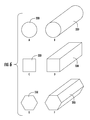
- FIG. 6A illustrates a cross-sectional view of a dampening element according to one embodiment of a tool holder assembly described herein having a circular cross-sectional shape.
- FIG. 6B illustrates a perspective view of the dampening element of FIG. 6A .
- FIG. 6C illustrates a cross-sectional view of a dampening element according to one embodiment of a tool holder assembly described herein having a square cross-sectional shape.
- FIG. 6D illustrates a perspective view of the dampening element of FIG. 6C .
- FIG. 6E illustrates a cross-sectional view of a dampening element according to one embodiment of a tool holder assembly described herein having a hexagonal cross-sectional shape.
- FIG. 6F illustrates a perspective view of the dampening element of FIG. 6E .
- the tool holder assembly ( 100 ) defines a central longitudinal axis (A-A) and comprises a tool holder body ( 200 ) and a tool receiver ( 300 ).
- the tool holder body ( 200 ) has a connector portion ( 210 ) and a holder portion ( 220 ), the connector portion ( 210 ) is structured to engage a rotary machine (not shown) and the holder portion ( 220 ) is disposed opposite the connector portion ( 210 ) and has an inner diameter surface ( 230 ) comprising a plurality of axial grooves ( 240 ).
- the tool receiver ( 300 ) is structured to receive at least a portion of a cutting tool (not shown), the tool receiver ( 300 ) having an outer diameter surface ( 310 ) comprising a plurality of axial grooves ( 320 ).
- the tool receiver ( 300 ) is mounted in the holder portion ( 220 ) so as to align the axial grooves ( 240 ) of the inner diameter surface ( 230 ) with the axial grooves ( 320 ) of the outer diameter surface ( 310 ) and define axial sleeves filled with dampening elements ( 330 ).
- Tool holder bodies can have any shape or configuration not inconsistent with the objectives of the present invention.
- a connector portion ( 210 ) of a tool holder body ( 200 ) can be structured or configured to engage a rotary machine in any manner.
- the connector portion ( 210 ) can be generally cylindrical, conical or frustoconical and can be structured or configured to engage a rotary machine by interference fit, resistance fit, or by clamping such as by a hydraulic clamp.
- the connector portion ( 210 ) may be structured or configured to be mechanically fastened or affixed to a rotary machine, such as by a bolt, pin or other fastener.
- the holder portion ( 220 ) can have any shape, architecture or configuration not inconsistent with the objectives of the present invention.
- the holder portion ( 220 ) is generally cylindrical, although other shapes are contemplated by the present disclosure.
- the holder portion ( 220 ) can have a polygonal cross-sectional shape.
- the holder portion ( 220 ) defines an inner diameter surface ( 230 ).
- the inner diameter surface ( 230 ) can be sized, shaped, or otherwise configured in any manner not inconsistent with the objectives of the present invention. For example, as illustrated in FIGS.
- the inner diameter surface ( 230 ) can be substantially cylindrical, although other geometries, such as polygonal, are also contemplated.
- the holder portion ( 220 ) comprises a plurality of axial grooves ( 240 ).
- the axial grooves ( 240 ) can have any size, shape, orientation, or configuration consistent with the disclosure of axial sleeves provided herein below. Further, the holder portion ( 220 ) can accommodate one or more locking pins or bolts for securing a cutting tool into position within the tool holder assembly ( 100 ). In the embodiments illustrated in FIGS.
- the holder portion ( 220 ) comprises at least two radial apertures ( 250 ) configured to receive corresponding radial locking pins or screws ( 500 ) for cutting tool securement.
- the tool holder body ( 200 ) can comprise an axial aperture (not shown) configured to receive a corresponding axial clamp screw ( 400 ).
- the axial clamp screw ( 400 ) passes through an aperture formed in the tool receiver ( 300 ) and threadingly engages the axial aperture in the tool holder body ( 200 ).
- a tool holder assembly described herein further comprises a tool receiver.
- Tool receivers ( 300 ) are structured to receive at least a portion of a cutting tool.
- a receiver surface ( 370 ) is provided of a size and/or shape corresponding to the desired cutting tool.
- the receiver surface ( 370 ) may have any desired size, shape or configuration.
- the receiver surface ( 370 ) may have a substantially circular cross-sectional shape. In certain other cases, a polygonal cross-section can be employed.
- the receiver surface ( 370 ) may have one or more linear portions or cut-out portions operable as a key, thereby permitting insertion of the cutting tool in only one or a limited number of rotational configurations.
- the receiver surface ( 370 ) may also have a diameter of sufficient size to permit one or more axial clamp screws ( 400 ) to be secured through an axial locking aperture ( 360 ) as illustrated in FIG. 3A , thereby permitting the tool receiver ( 300 ) to be coupled to the tool holder body ( 200 ).
- a tool receiver ( 300 ) can be configured to lockingly engage or otherwise restrict motion of the cutting tool, such as by one or more radial locking pins ( 500 ).
- the tool receiver ( 300 ) comprises at least two radial apertures ( 350 ) configured to receive radial locking pins ( 500 ), the radial apertures ( 350 ) corresponding to the apertures ( 250 ) of the tool holder portion ( 220 ) when assembled.
- the radial locking pins ( 500 ) are of sufficient length to additionally restrict motion between the tool receiver ( 300 ) and holder portion ( 220 ).
- the tool receiver ( 300 ) has an outer diameter surface ( 310 ) comprising a plurality of axial grooves ( 320 ) as illustrated in FIGS. 3A and 3B .
- the outer diameter surface ( 310 ) is sized and/or shaped in a manner corresponding to the inner diameter surface ( 230 ).
- the outer diameter surface ( 310 ) is substantially the same shape as the inner diameter surface ( 230 ) of the holder portion ( 220 ).
- the outer diameter surface ( 310 ) can have a diameter or cross-sectional width such that the tool receiver ( 300 ) can be inserted into the holder portion ( 220 ) without the outer diameter surface ( 310 ) contacting the inner diameter surface ( 230 ).
- the tool receiver ( 300 ) is configured to be mounted in the holder portion ( 220 ) so as to align the axial grooves ( 240 ) of the inner diameter surface ( 230 ) with the axial grooves ( 320 ) of the outer diameter surface ( 310 ) to define axial sleeves.
- Axial sleeves formed by axial grooves ( 240 , 320 ) can have any desired cross-sectional shape.
- the axial sleeves have a circular or elliptical cross-sectional profile.
- the axial sleeves have a polygonal cross-sectional profile.
- axial grooves ( 240 ) of the inner diameter surface ( 230 ) are of different cross-sectional profile than the axial grooves ( 320 ) of the outer diameter surface ( 310 ).
- at least one axial groove can have a substantially semi-circular cross-section, with the opposing axial groove having a polygonal cross-section.
- axial grooves ( 240 , 320 ) of the inner and outer diameter surfaces ( 230 , 310 ) are of the same cross-sectional profile.
- each axial groove forming the axial sleeve can have a semi-circular cross-sectional profile, resulting in a cylindrical axial sleeve.
- the axial grooves ( 240 ) of the inner diameter surface ( 230 ) and the axial grooves ( 320 ) of the outer diameter surface ( 310 ) forming the axial sleeves can be arranged and/or oriented in any manner.
- the axial grooves ( 240 , 320 ), in some embodiments, are parallel or substantially parallel with a central longitudinal axis (A-A) of the tool holder assembly.
- the axial grooves ( 240 ) of the inner diameter surface ( 230 ) and/or the axial grooves ( 320 ) of the outer diameter surface ( 310 ) are not parallel to the central longitudinal axis. Such an embodiment is illustrated in FIG.
- axial grooves ( 620 ) disposed on the outer diameter surface ( 610 ) having a central axis (C-C) non-parallel to the central longitudinal axis (A-A).
- the axial grooves ( 240 ) of the inner diameter surface ( 230 ) and the axial grooves ( 320 ) of the outer diameter surface ( 310 ) may be positioned to provide axial sleeves having any desired radial arrangement.
- the axial grooves ( 240 , 320 ) may be arranged generally helically about the outer diameter surface and/or inner diameter surface. Corresponding dampening elements disposed in the axial grooves ( 240 , 320 ) can be similarly arranged.
- the axial grooves ( 240 , 320 ) are positioned to provide axial sleeves having a symmetrical radial arrangement about the central longitudinal axis (A-A), as illustrated in FIGS. 3A and 3B .
- the axial grooves ( 240 , 320 ) of the inner and outer diameter surfaces ( 230 , 310 ) are positioned to provide sleeves having an asymmetrical radial arrangement about the central longitudinal axis (A-A).
- the number of axial grooves ( 320 ) on an outer diameter surface ( 310 ) can correspond to the number of axial grooves ( 240 ) on an inner diameter surface ( 230 ). In other embodiments, the number of axial grooves ( 320 ) on an outer diameter surface ( 310 ) differs from the number of axial grooves ( 240 ) on an inner diameter surface ( 230 ). Such an arrangement can permit selection of a number of axial sleeves to be utilized for a particular tool receiver ( 300 ), permitting interchangeability of different tool receivers ( 300 ) with a single tool holder ( 200 ).
- Axial sleeves formed by aligned axial grooves are filled with dampening elements.
- Dampening elements ( 330 ) are illustrated in FIGS. 1, 3A and 3B .
- “Filled,” for reference purposes herein, refers to a configuration whereby dampening elements are disposed within axial sleeves and take up all or substantially all of a cross-sectional profile formed by such sleeves.
- axial sleeves do not comprise or contain components or elements in addition to the dampening elements. Any number of dampening elements can be used.
- all or substantially all of the axial sleeves formed by axial grooves ( 240 , 320 ) are filled with dampening elements ( 330 ).
- dampening elements ( 330 ) can be formed by any material not inconsistent with the objectives of the present invention.
- a dampening element can be formed from an elastomer, plastic, or other material softer than the adjacent inner and outer diameter surfaces ( 230 , 310 ).
- a dampening element ( 330 ) can comprise, consist or consist essentially of neoprene, nitrile-butadiene, polyisoprene, a fluoroelastomer, rubber, silicone and/or combinations thereof.
- dampening elements ( 330 ) have a core or central portion faulted from a material that is not elastomeric.
- dampening elements ( 330 ) can have an inner portion ( 332 ) formed in part or entirely from metal or rigid plastic.
- FIG. 5 illustrates a dampening element ( 330 ) comprising an outer portion ( 331 ) formed from an elastomer, plastic, or other material softer than the adjacent inner and outer diameter surfaces ( 230 , 310 ).
- the inner portion ( 332 ) of the dampening element ( 330 ) of FIG. 5 is formed from a rigid component, for example faulted of metal or plastic.
- the dampening elements ( 330 ) can demonstrate increased capability for torque transmission applied to the tool holder assembly.
- Dampening elements can be encapsulated by, fastened to, and/or contained within axial sleeves in any manner or by any means not inconsistent with the objectives of the present invention.
- dampening elements ( 330 ) are not mechanically fastened to the axial grooves ( 240 , 320 ) of the outer diameter surface ( 310 ) or the inner diameter surface ( 230 ).
- the dampening elements ( 330 ) can be held in position within the axial sleeves primarily or entirely by frictional fit or compression.
- the dampening elements ( 330 ) may be fastened or connected to the axial sleeves by an adhesive.
- one or more of the inner diameter surface ( 230 ), outer diameter surface ( 310 ), and/or dampening elements ( 330 ) are sized, shaped, or otherwise configured such that the dampening elements ( 330 ) prevent contact of the tool receiver ( 300 ) and holder portion ( 220 ).
- axial grooves ( 320 ) on the outer diameter surface ( 310 ) and/or axial grooves ( 240 ) on the inner diameter surface ( 230 ) can each define a cross-sectional size less than 50% of the cross-sectional size of the dampening elements ( 330 ), thereby permitting the dampening elements ( 330 ) to prevent surface contact of the tool receiver ( 300 ) and holder portion ( 220 ). While the above description provides one embodiment of a configuration wherein dampening elements prevent contact of the tool receiver and holder portion, it is to be understood that other configurations are also possible. In such configurations, dampening elements ( 330 ) can be operable to dampen vibrational, rotational, and/or axial forces induced during a rotational cutting operation.
- tool holder assemblies described herein can further comprise at least one secondary dampening element ( 340 ) disposed on or about the outer diameter surface ( 310 ).
- a secondary dampening element can be circular or substantially circular, and can be disposed about the central longitudinal axis (A-A).
- Secondary dampening elements are, in some embodiments, operable to prevent contact of the tool receiver ( 300 ) and the connector portion ( 220 ) in at least an axial direction.
- secondary dampening elements are operable to dampen vibrational, rotational, and/or axial forces induced during a rotational cutting operation.
- a method described herein comprises providing a tool holder body having a connector portion and a holder portion.
- the connector portion is structured to engage a rotary machine, and the holder portion is disposed opposite the connector portion and has an inner diameter surface comprising a plurality of axial grooves.
- a tool receiver structured to receive at least a portion of a cutting tool is provided, the tool receiver having an outer diameter surface comprising a plurality of axial grooves.
- the tool receiver is mounted in the holder portion so as to align the axial grooves of the inner and outer diameter surfaces and define axial sleeves, wherein the axial sleeves are filled with dampening elements.
- any tool holder assembly can be used consistent with the above description in Section I.
- axial grooves of the outer diameter surface and associated dampening elements can be parallel to the central longitudinal axis, as illustrated in FIGS. 1, 3A, and 3B .
- the axial grooves of the outer diameter surface and associated dampening elements are not parallel to the central longitudinal axis, as illustrated in FIG. 4 .
- the dampening elements may be arranged generally helically about the outer diameter surface and/or inner diameter surface. Corresponding axial grooves can be similarly arranged so as to receive the dampening elements.
- dampening elements may operate to enact axial movement of the cutting tool when torque is applied to the tool holder assembly.
- dampening elements in some embodiments, are not mechanically fastened to the axial grooves of the outer diameter surface.
- axial grooves can be formed on the outer diameter surface so as to be symmetrical or substantially symmetrical to the axial grooves of the inner diameter surface.
- the axial sleeves can have a circular, elliptical, or polygonal cross-sectional profile.
- mounting the tool receiver in the holder portion can comprise filling the axial sleeves with dampening elements by positioning the dampening elements into the axial grooves of the outer diameter surface prior to mounting the tool receiver in the holder portion.
- the axial sleeves are filled with the dampening elements by positioning the dampening elements in the axial grooves of the inner diameter surface prior to mounting the tool receiver in the holder portion.
Landscapes
- Engineering & Computer Science (AREA)
- Mechanical Engineering (AREA)
- Jigs For Machine Tools (AREA)
- Gripping On Spindles (AREA)
Abstract
Description
Claims (21)
Priority Applications (1)
| Application Number | Priority Date | Filing Date | Title |
|---|---|---|---|
| US14/514,826 US9630258B2 (en) | 2014-10-15 | 2014-10-15 | Tool holder assembly with dampening elements |
Applications Claiming Priority (1)
| Application Number | Priority Date | Filing Date | Title |
|---|---|---|---|
| US14/514,826 US9630258B2 (en) | 2014-10-15 | 2014-10-15 | Tool holder assembly with dampening elements |
Publications (2)
| Publication Number | Publication Date |
|---|---|
| US20160107242A1 US20160107242A1 (en) | 2016-04-21 |
| US9630258B2 true US9630258B2 (en) | 2017-04-25 |
Family
ID=55748302
Family Applications (1)
| Application Number | Title | Priority Date | Filing Date |
|---|---|---|---|
| US14/514,826 Expired - Fee Related US9630258B2 (en) | 2014-10-15 | 2014-10-15 | Tool holder assembly with dampening elements |
Country Status (1)
| Country | Link |
|---|---|
| US (1) | US9630258B2 (en) |
Cited By (2)
| Publication number | Priority date | Publication date | Assignee | Title |
|---|---|---|---|---|
| US11534834B2 (en) * | 2019-07-17 | 2022-12-27 | Kennametal Inc. | Cutting tool holder with improved dampening effect |
| US12103091B2 (en) * | 2021-01-21 | 2024-10-01 | Iscar, Ltd. | Tool holder having anti-vibration arrangement and cutting tool provided with tool holder |
Families Citing this family (9)
| Publication number | Priority date | Publication date | Assignee | Title |
|---|---|---|---|---|
| WO2016000870A1 (en) * | 2014-06-30 | 2016-01-07 | Walter Ag | Anti-vibration damper |
| DE102015002483B4 (en) * | 2015-02-27 | 2024-10-31 | Rattunde Ag | Method and device for reducing the regenerative chatter of cutting machines |
| US10105768B2 (en) * | 2016-07-05 | 2018-10-23 | Ching-Ting Chen | Cutter holder with vibration resistant structure |
| US10179367B1 (en) * | 2018-02-07 | 2019-01-15 | Kun-Chi Lo | Damping arbor |
| US20190283140A1 (en) * | 2018-03-13 | 2019-09-19 | Chiu-Lien Yu | Cutter arbor damping device |
| CN108909358B (en) * | 2018-07-05 | 2021-09-10 | 中车青岛四方机车车辆股份有限公司 | Variable-gauge wheel set and variable-gauge bogie |
| CN108909359B (en) * | 2018-07-05 | 2021-06-25 | 中车青岛四方机车车辆股份有限公司 | A kind of axle box body structure for changing gauge wheelset and gauge changing wheelset |
| US11819928B2 (en) * | 2020-10-14 | 2023-11-21 | Iscar, Ltd. | Insert holder having insert receiving recess with insert orientation projection and cutting tool |
| EP4011531B1 (en) | 2020-12-14 | 2026-03-18 | Ceratizit Luxembourg Sàrl | Milling damping device |
Citations (73)
| Publication number | Priority date | Publication date | Assignee | Title |
|---|---|---|---|---|
| US357025A (en) | 1887-02-01 | Caster | ||
| US671447A (en) | 1898-07-12 | 1901-04-09 | Ralph L Morgan | Tap-driving head. |
| US956298A (en) | 1909-01-05 | 1910-04-26 | Laurence J Cudahy | Safety tap-holder. |
| US1290427A (en) | 1918-03-09 | 1919-01-07 | Joseph Velk | Tap and die chuck. |
| US1763717A (en) | 1924-08-11 | 1930-06-17 | Ingersoll Milling Machine Co | Tapping chuck |
| US2244143A (en) | 1940-05-28 | 1941-06-03 | Pacific Electric Mfg Corp | Tap driving chuck |
| US2392039A (en) | 1944-04-17 | 1946-01-01 | Victor W Gideon | Adjustable chuck |
| CH266434A (en) * | 1948-06-08 | 1950-01-31 | Furrer Albert | Pendulum chuck. |
| US2547518A (en) | 1949-11-30 | 1951-04-03 | Benjamin | Full-floating holder |
| US2570752A (en) | 1948-03-24 | 1951-10-09 | Benjamin | Floating toolholder |
| US2626029A (en) | 1946-01-09 | 1953-01-20 | Robert P Gutterman | Spring type overload release clutch |
| DE918980C (en) | 1951-01-09 | 1954-10-07 | Eibes Kerb Konus Gmbh | Screwing tool for threaded bushes |
| US2791433A (en) | 1952-11-27 | 1957-05-07 | Dodd John | Device for the attachment of tools, for tapping and studding operations to power operated drilling machines |
| US3343190A (en) | 1965-08-04 | 1967-09-26 | Warner Swasey Co | Tap holder |
| DE1917835A1 (en) | 1969-04-08 | 1970-10-15 | Sick Erwin | Digitally controlled translation |
| US3663116A (en) | 1969-04-23 | 1972-05-16 | Goetzewerke | Cantilevered machine part |
| US3688324A (en) | 1970-11-19 | 1972-09-05 | Maehr Lesnor Mfg | Tap holder |
| US3778071A (en) | 1972-01-31 | 1973-12-11 | Buck Tool Co | Floating tool holder |
| US3837758A (en) | 1971-08-25 | 1974-09-24 | Tiefbohr Technik Gmbh | Means for damping vibrations of tools in drilling machines or the like |
| US4080090A (en) | 1976-12-02 | 1978-03-21 | Houdaille Industries, Inc. | Tap driver assembly |
| SU643254A1 (en) | 1977-06-28 | 1979-01-25 | [^Е^-^лщткнГ | Face-milling cutter |
| SU664756A1 (en) | 1978-01-04 | 1979-05-30 | Ленинградский Ордена Красного Знамени Механический Институт | Boring rod for working deep openings |
| EP0051097A1 (en) | 1980-11-07 | 1982-05-12 | Kato Kohki Kabushiki Kaisha | Torque limiter |
| JPS58202720A (en) | 1982-05-19 | 1983-11-26 | Seiwa Seiki Kk | Tap holder |
| SU1061943A1 (en) | 1982-09-22 | 1983-12-23 | Ленинградский Ордена Ленина И Ордена Красного Знамени Механический Институт | Inserted-blade cutter |
| US4447181A (en) | 1982-09-07 | 1984-05-08 | Ikegai Tekko Kabushiki Kaisha | Tool holder |
| SU1094680A1 (en) | 1983-04-22 | 1984-05-30 | Предприятие П/Я А-7340 | Milling cutter arbor |
| US4491044A (en) | 1983-03-04 | 1985-01-01 | Cincinnati Milacron Inc. | Damped tool turret |
| SU1212713A1 (en) | 1984-03-29 | 1986-02-23 | Предприятие П/Я Р-6973 | Device for cleaning components |
| DE8505616U1 (en) | 1985-02-27 | 1986-06-26 | Werkzeugmaschinenfabrik Adolf Waldrich Coburg Gmbh & Co, 8630 Coburg | Tool adapter for a spindle of drilling, milling and similar machine tools |
| US4605349A (en) | 1985-01-07 | 1986-08-12 | Cincinnati Milacron Inc. | Spring centering device for tool spindles |
| SU1281347A1 (en) | 1985-05-22 | 1987-01-07 | Предприятие П/Я А-7885 | Tap chuck |
| SU1342615A1 (en) | 1986-02-25 | 1987-10-07 | Всесоюзный Научно-Исследовательский И Проектно-Конструкторский Институт Электроагрегатов И Передвижных Электростанций | Safety chuck |
| US4714389A (en) | 1985-02-13 | 1987-12-22 | J. Kuhn Gmbh Co. | Tool holder |
| DE3835879C1 (en) | 1988-10-21 | 1990-01-25 | Krupp Widia Gmbh, 4300 Essen, De | |
| US5033340A (en) | 1988-10-13 | 1991-07-23 | The Monarch Machine Tool Company | Apparatus and method for tool vibration damping |
| SU1750859A1 (en) | 1990-11-11 | 1992-07-30 | Тернопольский Филиал Львовского Политехнического Института Им.Ленинского Комсомола | Assembled end cutter |
| RU1780942C (en) | 1990-12-04 | 1992-12-15 | Тернопольский Филиал Львовского Политехнического Института Им.Ленинского Комсомола | Assembled face milling cutter |
| DE68902953T2 (en) | 1988-06-09 | 1993-03-25 | Aerospatiale | DRILLING MACHINE, ESPECIALLY FOR PROGRAMMABLE MACHINE. |
| DE4239769C2 (en) | 1992-11-26 | 1994-09-01 | Doerries Scharmann Gmbh | Device for fastening tools to a machine tool spindle or a tool holder |
| US5538371A (en) | 1995-01-24 | 1996-07-23 | Daishowa Seiki Co., Ltd. | Tapper mechanism |
| US5716173A (en) | 1994-09-26 | 1998-02-10 | Nikken Kosakusho Works, Ltd. | Tool holder |
| US5865575A (en) | 1996-09-24 | 1999-02-02 | The Tapmatic Corporation | Self-reversing tapping attachment with shock absorption |
| US5873687A (en) * | 1997-04-16 | 1999-02-23 | Mori Seiki Co., Ltd. | Tool unit with hydraulic feed passage |
| US5882015A (en) | 1997-08-27 | 1999-03-16 | John B. Packard | Floating toolholder |
| US5915892A (en) | 1997-06-19 | 1999-06-29 | Emuge-Werk Richard Glimpel Fabrik Fuer Praezisionswerkzeuge Vormals Moschkau & Glimpel | Thread-cutting chuck for CNC machine technology of rigid tapping |
| US5975816A (en) | 1997-07-09 | 1999-11-02 | Cook; Harold D. | Harmonic dampener for rotary tool holder |
| US6047621A (en) | 1998-02-27 | 2000-04-11 | Elba Electronetics, Inc. | Quick change adjustable punch tool assembly and method of adjustment |
| US6082236A (en) | 1995-09-21 | 2000-07-04 | Teeness A/S | Noise elminating adaptor for a cutting tool |
| US20010056013A1 (en) | 1997-07-09 | 2001-12-27 | Cook Harold D. | Vibration dampened spindle and tool holder assembly |
| CN1354707A (en) | 2000-04-10 | 2002-06-19 | 帕斯卡株式会社 | Tool holder mounting structure |
| US6537000B1 (en) | 1998-06-06 | 2003-03-25 | Manfred Weck | Tool fixing device in a tool holder |
| US6569022B2 (en) | 2000-07-31 | 2003-05-27 | Tapmatic, Inc. | Self-synchronizing tap driver for rigid tapping |
| US6599068B1 (en) | 2000-04-10 | 2003-07-29 | Pascal Kabushiki Kaisha | Tool holder |
| US20030147712A1 (en) | 2001-12-11 | 2003-08-07 | Yoshiaki Kai | Tool holder |
| US20030228199A1 (en) | 2002-06-10 | 2003-12-11 | Nikken Kosakusho Works Ltd. | Tool holder |
| DE60205935T2 (en) | 2001-11-05 | 2006-06-08 | Precimed S.A. | TORQUE TRANSMISSION COUPLING AND SURGICAL DEVICE |
| DE102004062443A1 (en) | 2004-12-16 | 2006-07-06 | Elgan-Diamantwerkzeuge Gmbh & Co. Kg | Honing unit incorporates a damping element which is located between the honing stones and the honing bar, and serves for damping out vibrations produced by the honing process |
| US20070231092A1 (en) | 2004-07-16 | 2007-10-04 | Mirko Flam | Tool Adapter |
| CN101076419A (en) | 2004-12-13 | 2007-11-21 | 雄克有限公司 | Clamping device |
| CN101119821A (en) | 2005-03-23 | 2008-02-06 | 弗朗茨·海默机械制造两合公司 | Tool fixture |
| US20080260483A1 (en) | 2007-04-18 | 2008-10-23 | Cook Harold D | Tool holder dampening system |
| CN101479070A (en) | 2006-10-31 | 2009-07-08 | 大昭和精机株式会社 | Tap holder |
| CN1929941B (en) | 2004-01-16 | 2010-10-06 | 弗朗茨·海默机械制造两合公司 | Vibration-absorbing tool holders |
| US20100310333A1 (en) | 2009-06-03 | 2010-12-09 | Klingelnberg Ag | Gearwheel cutting machine having vibration damping |
| US20110255932A1 (en) | 2010-03-04 | 2011-10-20 | Cook Harold D | Damping insert for tool holder |
| US20110266756A1 (en) | 2008-08-29 | 2011-11-03 | Franz Haimer Maschinenbau Kg | Damping sleeve |
| WO2011136463A1 (en) | 2010-04-30 | 2011-11-03 | Lee Hyun Joo | Modular type dual-contact shrink fit chuck with guide surface |
| US8118312B2 (en) | 2006-06-14 | 2012-02-21 | American Torch Tip Co. | Quick change centering tool holder |
| US20120207560A1 (en) | 2009-10-30 | 2012-08-16 | Yukiwa Seiko Kabushiki Kaisha | Tool holder |
| US20120301240A1 (en) | 2011-05-26 | 2012-11-29 | Jaeger Horst Manfred | Machine tool adapter to reduce vibrations and noise |
| US20140001715A1 (en) * | 2012-06-29 | 2014-01-02 | Kennametal Inc. | Tool adaptor having an integrated damping device |
| US20150231708A1 (en) * | 2014-02-18 | 2015-08-20 | Kennametal Inc. | Cylindrical grinding process and as-ground part resulting from such process |
-
2014
- 2014-10-15 US US14/514,826 patent/US9630258B2/en not_active Expired - Fee Related
Patent Citations (78)
| Publication number | Priority date | Publication date | Assignee | Title |
|---|---|---|---|---|
| US357025A (en) | 1887-02-01 | Caster | ||
| US671447A (en) | 1898-07-12 | 1901-04-09 | Ralph L Morgan | Tap-driving head. |
| US956298A (en) | 1909-01-05 | 1910-04-26 | Laurence J Cudahy | Safety tap-holder. |
| US1290427A (en) | 1918-03-09 | 1919-01-07 | Joseph Velk | Tap and die chuck. |
| US1763717A (en) | 1924-08-11 | 1930-06-17 | Ingersoll Milling Machine Co | Tapping chuck |
| US2244143A (en) | 1940-05-28 | 1941-06-03 | Pacific Electric Mfg Corp | Tap driving chuck |
| US2392039A (en) | 1944-04-17 | 1946-01-01 | Victor W Gideon | Adjustable chuck |
| US2626029A (en) | 1946-01-09 | 1953-01-20 | Robert P Gutterman | Spring type overload release clutch |
| US2570752A (en) | 1948-03-24 | 1951-10-09 | Benjamin | Floating toolholder |
| CH266434A (en) * | 1948-06-08 | 1950-01-31 | Furrer Albert | Pendulum chuck. |
| US2547518A (en) | 1949-11-30 | 1951-04-03 | Benjamin | Full-floating holder |
| DE918980C (en) | 1951-01-09 | 1954-10-07 | Eibes Kerb Konus Gmbh | Screwing tool for threaded bushes |
| US2791433A (en) | 1952-11-27 | 1957-05-07 | Dodd John | Device for the attachment of tools, for tapping and studding operations to power operated drilling machines |
| US3343190A (en) | 1965-08-04 | 1967-09-26 | Warner Swasey Co | Tap holder |
| DE1917835A1 (en) | 1969-04-08 | 1970-10-15 | Sick Erwin | Digitally controlled translation |
| US3663116A (en) | 1969-04-23 | 1972-05-16 | Goetzewerke | Cantilevered machine part |
| US3688324A (en) | 1970-11-19 | 1972-09-05 | Maehr Lesnor Mfg | Tap holder |
| US3837758A (en) | 1971-08-25 | 1974-09-24 | Tiefbohr Technik Gmbh | Means for damping vibrations of tools in drilling machines or the like |
| US3778071A (en) | 1972-01-31 | 1973-12-11 | Buck Tool Co | Floating tool holder |
| US4080090A (en) | 1976-12-02 | 1978-03-21 | Houdaille Industries, Inc. | Tap driver assembly |
| SU643254A1 (en) | 1977-06-28 | 1979-01-25 | [^Е^-^лщткнГ | Face-milling cutter |
| SU664756A1 (en) | 1978-01-04 | 1979-05-30 | Ленинградский Ордена Красного Знамени Механический Институт | Boring rod for working deep openings |
| EP0051097A1 (en) | 1980-11-07 | 1982-05-12 | Kato Kohki Kabushiki Kaisha | Torque limiter |
| JPS58202720A (en) | 1982-05-19 | 1983-11-26 | Seiwa Seiki Kk | Tap holder |
| US4447181A (en) | 1982-09-07 | 1984-05-08 | Ikegai Tekko Kabushiki Kaisha | Tool holder |
| SU1061943A1 (en) | 1982-09-22 | 1983-12-23 | Ленинградский Ордена Ленина И Ордена Красного Знамени Механический Институт | Inserted-blade cutter |
| US4491044A (en) | 1983-03-04 | 1985-01-01 | Cincinnati Milacron Inc. | Damped tool turret |
| SU1094680A1 (en) | 1983-04-22 | 1984-05-30 | Предприятие П/Я А-7340 | Milling cutter arbor |
| SU1212713A1 (en) | 1984-03-29 | 1986-02-23 | Предприятие П/Я Р-6973 | Device for cleaning components |
| US4605349A (en) | 1985-01-07 | 1986-08-12 | Cincinnati Milacron Inc. | Spring centering device for tool spindles |
| US4714389A (en) | 1985-02-13 | 1987-12-22 | J. Kuhn Gmbh Co. | Tool holder |
| DE8505616U1 (en) | 1985-02-27 | 1986-06-26 | Werkzeugmaschinenfabrik Adolf Waldrich Coburg Gmbh & Co, 8630 Coburg | Tool adapter for a spindle of drilling, milling and similar machine tools |
| SU1281347A1 (en) | 1985-05-22 | 1987-01-07 | Предприятие П/Я А-7885 | Tap chuck |
| SU1342615A1 (en) | 1986-02-25 | 1987-10-07 | Всесоюзный Научно-Исследовательский И Проектно-Конструкторский Институт Электроагрегатов И Передвижных Электростанций | Safety chuck |
| DE68902953T2 (en) | 1988-06-09 | 1993-03-25 | Aerospatiale | DRILLING MACHINE, ESPECIALLY FOR PROGRAMMABLE MACHINE. |
| US5033340A (en) | 1988-10-13 | 1991-07-23 | The Monarch Machine Tool Company | Apparatus and method for tool vibration damping |
| DE3835879C1 (en) | 1988-10-21 | 1990-01-25 | Krupp Widia Gmbh, 4300 Essen, De | |
| SU1750859A1 (en) | 1990-11-11 | 1992-07-30 | Тернопольский Филиал Львовского Политехнического Института Им.Ленинского Комсомола | Assembled end cutter |
| RU1780942C (en) | 1990-12-04 | 1992-12-15 | Тернопольский Филиал Львовского Политехнического Института Им.Ленинского Комсомола | Assembled face milling cutter |
| DE4239769C2 (en) | 1992-11-26 | 1994-09-01 | Doerries Scharmann Gmbh | Device for fastening tools to a machine tool spindle or a tool holder |
| US5716173A (en) | 1994-09-26 | 1998-02-10 | Nikken Kosakusho Works, Ltd. | Tool holder |
| US5538371A (en) | 1995-01-24 | 1996-07-23 | Daishowa Seiki Co., Ltd. | Tapper mechanism |
| US6082236A (en) | 1995-09-21 | 2000-07-04 | Teeness A/S | Noise elminating adaptor for a cutting tool |
| US5865575A (en) | 1996-09-24 | 1999-02-02 | The Tapmatic Corporation | Self-reversing tapping attachment with shock absorption |
| US5873687A (en) * | 1997-04-16 | 1999-02-23 | Mori Seiki Co., Ltd. | Tool unit with hydraulic feed passage |
| US5915892A (en) | 1997-06-19 | 1999-06-29 | Emuge-Werk Richard Glimpel Fabrik Fuer Praezisionswerkzeuge Vormals Moschkau & Glimpel | Thread-cutting chuck for CNC machine technology of rigid tapping |
| US20010056013A1 (en) | 1997-07-09 | 2001-12-27 | Cook Harold D. | Vibration dampened spindle and tool holder assembly |
| US5975816A (en) | 1997-07-09 | 1999-11-02 | Cook; Harold D. | Harmonic dampener for rotary tool holder |
| US6071219A (en) | 1997-07-09 | 2000-06-06 | Cook; Harold D. | Method and apparatus for mitigating vibration associated with rotary cutting machines |
| US5882015A (en) | 1997-08-27 | 1999-03-16 | John B. Packard | Floating toolholder |
| US6047621A (en) | 1998-02-27 | 2000-04-11 | Elba Electronetics, Inc. | Quick change adjustable punch tool assembly and method of adjustment |
| DE19982996B4 (en) | 1998-02-27 | 2008-01-03 | Amada Tool America Inc. | Adjustable quick-change punching tool arrangement |
| US6537000B1 (en) | 1998-06-06 | 2003-03-25 | Manfred Weck | Tool fixing device in a tool holder |
| CN1354707A (en) | 2000-04-10 | 2002-06-19 | 帕斯卡株式会社 | Tool holder mounting structure |
| US6599068B1 (en) | 2000-04-10 | 2003-07-29 | Pascal Kabushiki Kaisha | Tool holder |
| US6569022B2 (en) | 2000-07-31 | 2003-05-27 | Tapmatic, Inc. | Self-synchronizing tap driver for rigid tapping |
| DE60205935T2 (en) | 2001-11-05 | 2006-06-08 | Precimed S.A. | TORQUE TRANSMISSION COUPLING AND SURGICAL DEVICE |
| US20030147712A1 (en) | 2001-12-11 | 2003-08-07 | Yoshiaki Kai | Tool holder |
| US20030228199A1 (en) | 2002-06-10 | 2003-12-11 | Nikken Kosakusho Works Ltd. | Tool holder |
| CN1929941B (en) | 2004-01-16 | 2010-10-06 | 弗朗茨·海默机械制造两合公司 | Vibration-absorbing tool holders |
| US20070231092A1 (en) | 2004-07-16 | 2007-10-04 | Mirko Flam | Tool Adapter |
| CN101076419A (en) | 2004-12-13 | 2007-11-21 | 雄克有限公司 | Clamping device |
| DE102004062443A1 (en) | 2004-12-16 | 2006-07-06 | Elgan-Diamantwerkzeuge Gmbh & Co. Kg | Honing unit incorporates a damping element which is located between the honing stones and the honing bar, and serves for damping out vibrations produced by the honing process |
| CN101119821A (en) | 2005-03-23 | 2008-02-06 | 弗朗茨·海默机械制造两合公司 | Tool fixture |
| CN101797651A (en) | 2005-03-23 | 2010-08-11 | 弗朗茨·海默机械制造两合公司 | Tool holder |
| US8118312B2 (en) | 2006-06-14 | 2012-02-21 | American Torch Tip Co. | Quick change centering tool holder |
| US20090209356A1 (en) | 2006-10-31 | 2009-08-20 | Daishowa Seiki Co., Ltd. | Tap Holder |
| CN101479070A (en) | 2006-10-31 | 2009-07-08 | 大昭和精机株式会社 | Tap holder |
| US20080260483A1 (en) | 2007-04-18 | 2008-10-23 | Cook Harold D | Tool holder dampening system |
| US8043036B2 (en) | 2007-04-18 | 2011-10-25 | Cook Harold D | Tool holder dampening system |
| US20110266756A1 (en) | 2008-08-29 | 2011-11-03 | Franz Haimer Maschinenbau Kg | Damping sleeve |
| US20100310333A1 (en) | 2009-06-03 | 2010-12-09 | Klingelnberg Ag | Gearwheel cutting machine having vibration damping |
| US20120207560A1 (en) | 2009-10-30 | 2012-08-16 | Yukiwa Seiko Kabushiki Kaisha | Tool holder |
| US20110255932A1 (en) | 2010-03-04 | 2011-10-20 | Cook Harold D | Damping insert for tool holder |
| WO2011136463A1 (en) | 2010-04-30 | 2011-11-03 | Lee Hyun Joo | Modular type dual-contact shrink fit chuck with guide surface |
| US20120301240A1 (en) | 2011-05-26 | 2012-11-29 | Jaeger Horst Manfred | Machine tool adapter to reduce vibrations and noise |
| US20140001715A1 (en) * | 2012-06-29 | 2014-01-02 | Kennametal Inc. | Tool adaptor having an integrated damping device |
| US20150231708A1 (en) * | 2014-02-18 | 2015-08-20 | Kennametal Inc. | Cylindrical grinding process and as-ground part resulting from such process |
Non-Patent Citations (7)
| Title |
|---|
| German Patent Office Official Action dated Feb. 8, 2012 (no English language translation available), 5 pp. |
| Jun. 23, 2016—First Office Action. |
| Jun. 5, 2014—Non-Final Office Action—U.S. Appl. No. 13/538,337. |
| Mar. 6, 2015—Third—Office—Action—DE102013106589.9 and English translation. |
| May 4, 2016—Second—Office—Action—CN201210158571.9. |
| Non-Final Rejection dated Nov. 18, 2014. |
| Sep. 1, 2015—First—Office—Action—CN20121015857.9 and English translation. |
Cited By (3)
| Publication number | Priority date | Publication date | Assignee | Title |
|---|---|---|---|---|
| US11534834B2 (en) * | 2019-07-17 | 2022-12-27 | Kennametal Inc. | Cutting tool holder with improved dampening effect |
| US12053826B2 (en) | 2019-07-17 | 2024-08-06 | Kennametal Inc. | Cutting tool holder with improved dampening effect |
| US12103091B2 (en) * | 2021-01-21 | 2024-10-01 | Iscar, Ltd. | Tool holder having anti-vibration arrangement and cutting tool provided with tool holder |
Also Published As
| Publication number | Publication date |
|---|---|
| US20160107242A1 (en) | 2016-04-21 |
Similar Documents
| Publication | Publication Date | Title |
|---|---|---|
| US9630258B2 (en) | Tool holder assembly with dampening elements | |
| RU2342241C2 (en) | Clamp assembly | |
| KR101965173B1 (en) | Screwdriving tool and tool holder for such a screwdriving tool | |
| RU2400330C2 (en) | Tool holder characterised by low vibration | |
| US8322258B2 (en) | Tool holder | |
| CN103506866B (en) | Bit adaptor with the damping unit integrated | |
| US9174285B2 (en) | Positioning sleeve assembly adapted for engaging with different tool parts | |
| US9839965B2 (en) | Clamping device | |
| US20170001248A1 (en) | Indexable drill insert and rotary cutting tool employing same | |
| RU2008144196A (en) | STOPPING PREVENTING EXTRACTION OF TOOLS FROM HOLDERS WITH THE SOCKET FOR THE TOOL | |
| JP2015509854A5 (en) | ||
| US20160167188A1 (en) | Collets and tool holder assemblies employing the same | |
| CN103964238B (en) | Slitter machine unrolling fixing device and high-speed slitter machine | |
| US11298757B2 (en) | Firmly assembled cutter holding assembly | |
| CN105108213A (en) | Elastic clamping spring with safety lock structure and tool fixing structure with safety lock structure | |
| KR20180077630A (en) | The possible index boring bar holder | |
| US20200130129A1 (en) | Cutter holder capable of polishing | |
| CN211565208U (en) | Valve barrel pinhole adds clamping apparatus | |
| KR20160050372A (en) | Boring bar holder apparatus | |
| DE10305601B4 (en) | tool adapter | |
| KR20100086710A (en) | Chuck for tool | |
| KR102056442B1 (en) | Spindle unit | |
| KR101825640B1 (en) | The collet fixture for preventing the ingress of foreign matter | |
| KR102094909B1 (en) | Tool Holder For Machine Tools | |
| CN222754470U (en) | Positioning fixture for drilling |
Legal Events
| Date | Code | Title | Description |
|---|---|---|---|
| AS | Assignment |
Owner name: KENNAMETAL INC., PENNSYLVANIA Free format text: ASSIGNMENT OF ASSIGNORS INTEREST;ASSIGNORS:MCCORMICK, MICHAEL R.;FILHO, RUY FROTA DE SOUZA;SIGNING DATES FROM 20141009 TO 20141015;REEL/FRAME:033954/0263 |
|
| STCF | Information on status: patent grant |
Free format text: PATENTED CASE |
|
| MAFP | Maintenance fee payment |
Free format text: PAYMENT OF MAINTENANCE FEE, 4TH YEAR, LARGE ENTITY (ORIGINAL EVENT CODE: M1551); ENTITY STATUS OF PATENT OWNER: LARGE ENTITY Year of fee payment: 4 |
|
| FEPP | Fee payment procedure |
Free format text: MAINTENANCE FEE REMINDER MAILED (ORIGINAL EVENT CODE: REM.); ENTITY STATUS OF PATENT OWNER: LARGE ENTITY |
|
| LAPS | Lapse for failure to pay maintenance fees |
Free format text: PATENT EXPIRED FOR FAILURE TO PAY MAINTENANCE FEES (ORIGINAL EVENT CODE: EXP.); ENTITY STATUS OF PATENT OWNER: LARGE ENTITY |
|
| STCH | Information on status: patent discontinuation |
Free format text: PATENT EXPIRED DUE TO NONPAYMENT OF MAINTENANCE FEES UNDER 37 CFR 1.362 |
|
| FP | Lapsed due to failure to pay maintenance fee |
Effective date: 20250425 |