US9622196B2 - UL control channel consideration for heterogeneous networks - Google Patents
UL control channel consideration for heterogeneous networks Download PDFInfo
- Publication number
- US9622196B2 US9622196B2 US15/028,664 US201515028664A US9622196B2 US 9622196 B2 US9622196 B2 US 9622196B2 US 201515028664 A US201515028664 A US 201515028664A US 9622196 B2 US9622196 B2 US 9622196B2
- Authority
- US
- United States
- Prior art keywords
- dpcch
- transmit power
- network node
- power control
- user equipment
- Prior art date
- Legal status (The legal status is an assumption and is not a legal conclusion. Google has not performed a legal analysis and makes no representation as to the accuracy of the status listed.)
- Active
Links
Images


Classifications
-
- H—ELECTRICITY
- H04—ELECTRIC COMMUNICATION TECHNIQUE
- H04W—WIRELESS COMMUNICATION NETWORKS
- H04W52/00—Power management, e.g. TPC [Transmission Power Control], power saving or power classes
- H04W52/04—TPC
- H04W52/30—TPC using constraints in the total amount of available transmission power
- H04W52/32—TPC of broadcast or control channels
- H04W52/325—Power control of control or pilot channels
-
- H—ELECTRICITY
- H04—ELECTRIC COMMUNICATION TECHNIQUE
- H04W—WIRELESS COMMUNICATION NETWORKS
- H04W72/00—Local resource management
- H04W72/20—Control channels or signalling for resource management
- H04W72/21—Control channels or signalling for resource management in the uplink direction of a wireless link, i.e. towards the network
-
- H—ELECTRICITY
- H04—ELECTRIC COMMUNICATION TECHNIQUE
- H04W—WIRELESS COMMUNICATION NETWORKS
- H04W52/00—Power management, e.g. TPC [Transmission Power Control], power saving or power classes
- H04W52/04—TPC
- H04W52/38—TPC being performed in particular situations
- H04W52/40—TPC being performed in particular situations during macro-diversity or soft handoff
-
- H04W72/0406—
-
- H—ELECTRICITY
- H04—ELECTRIC COMMUNICATION TECHNIQUE
- H04W—WIRELESS COMMUNICATION NETWORKS
- H04W72/00—Local resource management
- H04W72/04—Wireless resource allocation
- H04W72/044—Wireless resource allocation based on the type of the allocated resource
- H04W72/0473—Wireless resource allocation based on the type of the allocated resource the resource being transmission power
-
- H—ELECTRICITY
- H04—ELECTRIC COMMUNICATION TECHNIQUE
- H04W—WIRELESS COMMUNICATION NETWORKS
- H04W72/00—Local resource management
- H04W72/20—Control channels or signalling for resource management
-
- H—ELECTRICITY
- H04—ELECTRIC COMMUNICATION TECHNIQUE
- H04W—WIRELESS COMMUNICATION NETWORKS
- H04W72/00—Local resource management
- H04W72/20—Control channels or signalling for resource management
- H04W72/23—Control channels or signalling for resource management in the downlink direction of a wireless link, i.e. towards a terminal
-
- H—ELECTRICITY
- H04—ELECTRIC COMMUNICATION TECHNIQUE
- H04W—WIRELESS COMMUNICATION NETWORKS
- H04W52/00—Power management, e.g. TPC [Transmission Power Control], power saving or power classes
- H04W52/04—TPC
- H04W52/06—TPC algorithms
- H04W52/14—Separate analysis of uplink or downlink
- H04W52/143—Downlink power control
-
- H—ELECTRICITY
- H04—ELECTRIC COMMUNICATION TECHNIQUE
- H04W—WIRELESS COMMUNICATION NETWORKS
- H04W52/00—Power management, e.g. TPC [Transmission Power Control], power saving or power classes
- H04W52/04—TPC
- H04W52/06—TPC algorithms
- H04W52/14—Separate analysis of uplink or downlink
- H04W52/146—Uplink power control
-
- H—ELECTRICITY
- H04—ELECTRIC COMMUNICATION TECHNIQUE
- H04W—WIRELESS COMMUNICATION NETWORKS
- H04W52/00—Power management, e.g. TPC [Transmission Power Control], power saving or power classes
- H04W52/04—TPC
- H04W52/18—TPC being performed according to specific parameters
- H04W52/24—TPC being performed according to specific parameters using SIR [Signal to Interference Ratio] or other wireless path parameters
- H04W52/241—TPC being performed according to specific parameters using SIR [Signal to Interference Ratio] or other wireless path parameters taking into account channel quality metrics, e.g. SIR, SNR, CIR, Eb/lo
Definitions
- the present disclosure relates, in general, to wireless communications and, more particularly, to uplink control channel transmissions in heterogeneous networks.
- a wireless device may communicate with one or more radio network nodes to send and/or receive information, such as voice traffic, data traffic, control signals, and so on.
- the wireless device may have a connection with multiple radio network nodes of different link quality.
- a problem may arise where important control information is to be transmitted to the wireless device, but the link quality with a particular radio network node is weak.
- WCDMA Wideband Code Division Multiple Access
- SHO soft handover
- UL uplink
- the best UL is a non-serving cell, it may be difficult to ensure that important control information is reliably received at the serving cell.
- the problem of weak communication links becomes particularly pronounced when the imbalance between the best UL and downlink (DL) becomes large, such as for heterogeneous networks or multi-flow operation.
- LPNs low-power nodes
- RRU remote radio unit
- a LPN may correspond, for example, to a remote radio unit (RRU), pico, or micro base station.
- LPNs may allow expansion of network capacity in a cost-efficient way.
- a network consisting of traditional macro NodeBs and LPNs is referred to as a heterogeneous network. Heterogeneous network deployment may be particularly useful in situations where there are coverage holes, as well as for capacity enhancement for localized traffic hotspots.
- FIG. 1 is a block diagram illustrating an embodiment of a network 100 .
- Network 100 includes one or more wireless devices 110 , radio network nodes 115 , radio network controller 120 , and core network node 130 .
- Network 100 may be any suitable type of network.
- network 100 may be a heterogeneous network of the kind described above, and network nodes 115 may be a mixture of macro nodes and LPNs.
- Wireless device 110 may communicate with a radio network node 115 over a wireless interface.
- wireless device 110 may transmit wireless signals to radio network node 115 and/or receive wireless signals from radio network node 115 .
- the wireless signals may contain voice traffic, data traffic, control signals, and/or any other suitable information.
- Radio network node 115 may interface with radio network controller 120 .
- Radio network controller 120 may control radio network node 115 and may provide certain radio resource management functions, mobility management functions, and/or other suitable functions.
- Radio network controller 120 may interface with core network node 130 .
- radio network controller 120 may interface with core network node 130 via an interconnecting network.
- the interconnecting network may refer to any interconnecting system capable of transmitting audio, video, signals, data, messages, or any combination of the preceding.
- the interconnecting network may include all or a portion of a public switched telephone network (PSTN), a public or private data network, a local area network (LAN), a metropolitan area network (MAN), a wide area network (WAN), a local, regional, or global communication or computer network such as the Internet, a wireline or wireless network, an enterprise intranet, or any other suitable communication link, including combinations thereof.
- PSTN public switched telephone network
- LAN local area network
- MAN metropolitan area network
- WAN wide area network
- Internet a local, regional, or global communication or computer network
- wireline or wireless network such as the Internet
- enterprise intranet an enterprise intranet, or any other suitable communication link, including combinations thereof.
- core network node 130 may manage the establishment of communication sessions and various other functionality for wireless device 110 .
- Wireless device 110 may exchange certain signals with core network node 130 using the non-access stratum layer.
- signals between wireless device 110 and core network node 130 may be transparently passed through the radio access network.
- Example embodiments of wireless device 110 , radio network node 115 , and a network node are described with respect to FIGS. 8, 9, and 10 , respectively.
- Wireless device 110 may communicate with multiple radio network nodes 115 .
- the communication links between wireless device 110 and radio network nodes 115 may be of differing quality. Where important control information is to be transmitted to wireless device 110 , but the link quality with a particular radio access node is weak, certain techniques may be used to ensure receipt of the control information.
- FIG. 2 illustrates a traditional HSPA deployment scenario with two radio network nodes 115 A and 115 B having similar transmit power levels, in accordance with certain embodiments.
- network nodes 115 A and 115 B may both be macro nodes with similar transmit power levels.
- UE 110 A moving from serving cell 115 A towards non-serving cell 115 B would enter the SHO region at point A 204 .
- a serving cell change would occur.
- the non-serving cell becomes the serving cell and vice versa.
- the current serving cell would become the non-serving cell, and the current non-serving cell 115 B would become the serving cell.
- UE 110 A would leave the SHO region.
- a radio network controller such as radio network controller 120 described above in relation to FIG. 1 , is in control of reconfigurations. This may imply rather long delays for performing a cell change.
- UE 110 A is power-controlled by the best uplink cell.
- network nodes 115 A and 115 B have roughly the same transmit power, so the optimal DL and UL cell borders will coincide, i.e., the path loss from UE 110 A to network nodes 115 A and 115 B will be equal at point B 206 .
- the serving cell 115 A would always have the best uplink.
- UE 110 A might be power controlled by non-serving cell 115 B during SHO.
- problems may arise due to the weaker link between serving cell 115 A and UE 110 A.
- receiving essential control channel information such as hybrid automatic repeat request (HARQ) positive acknowledgement/negative acknowledgement (ACK/NACK) feedback for HSDPA and scheduling information for Enhanced Uplink (EUL)
- HARQ hybrid automatic repeat request
- ACK/NACK positive acknowledgement/negative acknowledgement
- EUL Enhanced Uplink
- TPC downlink transmit power control
- F-DPCH fractional dedicated physical channel
- FIG. 3 illustrates a HSPA deployment scenario with two radio network nodes 115 A, 115 B having different transmit power levels, in accordance with certain embodiments.
- radio network node 115 A is a macro node
- radio network node 115 B is a LPN. Since macro node 115 A and LPN 115 B have different transmit power levels, the UL and downlink (DL) cell borders may not necessarily coincide.
- wireless device 110 A has a smaller path loss to LPN 115 B, while the strongest received power is from macro node 115 A. In such a scenario, the UL is better served by LPN 115 B, while the DL is provided by serving macro node 115 A.
- the region between the equal path loss border and equal downlink received power (e.g., common pilot channel (CPICH) receive power) border may be referred to as an imbalance region.
- CPICH common pilot channel
- the imbalance region some fundamental problems may be encountered.
- wireless device 110 A in position A 302 would have macro node 115 A as the serving cell, but be power controlled towards LPN 115 B. Due to the UL-DL imbalance, the UL towards serving macro node 115 A may be very weak. In such circumstances, important control information might not be reliably decoded in serving cell 115 A.
- This problem may be addressed to some extent by utilizing available RNC based cell selection offset parameters.
- CIO Cell Individual Offset
- the handover border can be shifted towards the optimal UL border.
- the IN_RANGE and OUT_RANGE parameters may be adjusted in order to extend the SHO region.
- FIG. 4 illustrates SHO operation for HSPA in a heterogeneous deployment with range extension, in accordance with certain embodiments.
- FIG. 4 includes two radio network nodes 115 A and 115 B having different transmit power levels. More particularly, radio network node 115 A is a macro node, and radio network node 115 B is a LPN.
- FIG. 4 illustrates the effect of adjustments to the CIO parameter described above. While the adjustments to the CIO parameter may be beneficial from a system performance point of view, in certain heterogeneous networks the power difference between macro node 115 A and LPN 115 B may be more than 10 dB. In practice, it is unlikely the CIO parameter will be set to more than 6 dB due to considerations such as DL signaling cost in terms of radio resource consumption. As a result, the imbalance region may not be eliminated by means of CIO setting.
- Possible solutions to the above described problems may include increasing the gain factors by means of RRC signaling, utilizing repetition or relying on HARQ. Note, however, that possible imbalances between UL and DL in a macro only network are mainly caused by fast fading in a traditional deployment, whereas for other scenarios, such as heterogeneous networks, other factors make the imbalance more pronounced. Thus, the possible solutions mentioned above may be less effective in a heterogeneous network.
- SI secondary pilot channel
- the method comprises providing to a user equipment a dedicated physical control channel (DPCCH), the DPCCH having an associated first fractional dedicated physical channel (F-DPCH) for conveying transmit power control commands to the user equipment for power controlling the DPCCH.
- the method further comprises providing to the user equipment a secondary dedicated physical control channel (S-DPCCH), the S-DPCCH comprising an uplink control channel for communicating transmit power control commands, the S-DPCCH having an associated second F-DPCH for conveying transmit power control commands to the user equipment for power controlling the S-DPCCH.
- DPCCH dedicated physical control channel
- F-DPCH fractional dedicated physical channel
- S-DPCCH secondary dedicated physical control channel
- the method further comprises receiving, from the user equipment, a downlink transmit power control command, the downlink transmit power control command carried on the S-DPCCH, and controlling a transmit power of the second F-DPCH associated with the S-DPCCH based on the downlink transmit power control command carried on the S-DPCCH.
- the network node may be a serving cell.
- the method may further comprise controlling a transmit power of the first F-DPCH associated with the DPCCH based on the downlink transmit power control command carried on the S-DPCCH.
- the method may comprise receiving additional control signaling on the S-DPCCH.
- the S-DPCCH may be power controlled only by the network node.
- the S-DPCCH may be the phase reference for one or more channels and/or the basis for setting the transmit power or amplitude level for one or more channels.
- the method may further comprise communicating to the user equipment an uplink transmit power control command on a downlink connection with the user equipment.
- the uplink transmit power control command may be for power controlling the S-DPCCH.
- the network node comprises one or more processors.
- the one or more processors are configured to provide to a user equipment a dedicated physical control channel (DPCCH), the DPCCH having an associated first fractional dedicated physical channel (F-DPCH) for conveying transmit power control commands to the user equipment for power controlling the DPCCH.
- the one or more processors are configured to provide to the user equipment a secondary dedicated physical control channel (S-DPCCH), the S-DPCCH comprising an uplink control channel for communicating transmit power control commands, the S-DPCCH having an associated second F-DPCH for conveying transmit power control commands to the user equipment for power controlling the S-DPCCH.
- DPCCH dedicated physical control channel
- F-DPCH fractional dedicated physical channel
- S-DPCCH secondary dedicated physical control channel
- the one or more processors are configured to receive, from the user equipment, a downlink transmit power control command, the downlink transmit power control command carried on the S-DPCCH, and to control a transmit power of the second F-DPCH associated with the S-DPCCH based on the downlink transmit power control command carried on the S-DPCCH.
- the method comprises receiving provisioning by a network node of a dedicated physical control channel (DPCCH), the DPCCH having an associated first fractional dedicated physical channel (F-DPCH) for conveying transmit power control commands to the user equipment for power controlling the DPCCH.
- the method further comprises receiving provisioning by the network node of a secondary dedicated physical control channel (S-DPCCH), the S-DPCCH comprising an uplink control channel for communicating transmit power control commands, the S-DPCCH having an associated second F-DPCH for conveying transmit power control commands to the user equipment for power controlling the S-DPCCH.
- the method further comprises communicating, to the network node, a downlink transmit power control command, the downlink transmit power control command carried on the S-DPCCH.
- the downlink transmit power control command carried on the S-DPCCH may be a first downlink transmit power control command, the first downlink transmit power control command used by the network node for controlling a transmit power of the second F-DPCH, and the method may further comprise determining the first downlink transmit power control command based at least in part on one or more of a power, a signal-to-interference ratio, and a signal-to-interference-and-noise ratio of the second F-DPCH.
- the method may further comprise determining a second downlink transmit power control command based at least in part on one or more of a power, a signal-to-interference ratio, and a signal-to-interference-and-noise ratio of a third F-DPCH associated with the DPCCH and transmitted by a second network node.
- the second downlink transmit power control command may be used by the second network node for controlling a transmit power of the third F-DPCH.
- the method may further comprise communicating, to the second network node, the second downlink transmit power control command, the second downlink transmit power control command carried on the DPCCH.
- the network node may be a serving cell, and the second network node may be a non-serving cell.
- the method may further comprise receiving an uplink transmit power control command on a downlink connection with the network node, the uplink transmit power control command for power controlling the S-DPCCH.
- the S-DPCCH may be used to carry additional control signaling, and may be power controlled only by the network node.
- the S-DPCCH may be the phase reference for one or more channels and/or the basis for setting the transmit power or amplitude level for one or more channels.
- the user equipment comprises one or more processors.
- the one or more processors are configured to receive provisioning by a network node of a dedicated physical control channel (DPCCH), the DPCCH having an associated first fractional dedicated physical channel (F-DPCH) for conveying transmit power control commands to the user equipment for power controlling the DPCCH.
- the one or more processors are configured to receive provisioning by the network node of a secondary dedicated physical control channel (S-DPCCH), the S-DPCCH comprising an uplink control channel for communicating transmit power control commands, the S-DPCCH having an associated second F-DPCH for conveying transmit power control commands to the user equipment for power controlling the S-DPCCH.
- the one or more processors are configured to communicate, to the network node, a downlink transmit power control command, the downlink transmit power control command carried on the S-DPCCH.
- FIG. 1 is a block diagram illustrating an embodiment of a network, in accordance with certain embodiments
- FIG. 2 illustrates a traditional HSPA deployment scenario with two radio network nodes having similar transmit power levels, in accordance with certain embodiments
- FIG. 3 illustrates a HSPA deployment scenario with two radio network nodes having different transmit power levels, in accordance with certain embodiments
- FIG. 4 illustrates SHO operation for HSPA in a heterogeneous deployment with range extension, in accordance with certain embodiments
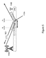
- FIG. 5 illustrates a secondary pilot channel based solution for reception of essential control information on the serving cell side, in accordance with certain embodiments
- FIG. 6 is a flow diagram illustrating an example method in a network node, according to a particular embodiment
- FIG. 7 is a flow diagram illustrating an example method in a user equipment, according to a particular embodiment
- FIG. 8 is a block diagram illustrating certain embodiments of a wireless device
- FIG. 9 is a block diagram illustrating certain embodiments of a radio network node.
- FIG. 10 is a block diagram illustrating certain embodiments of a core network node.
- FIGS. 1-10 of the drawings like numerals being used for like and corresponding parts of the various drawings.
- problems may arise where important control information is to be transmitted to a wireless device, but the link quality with a particular radio network node is weak.
- the problem of weak communication links becomes particularly pronounced when the imbalance between the best UL and downlink (DL) becomes large, such as for heterogeneous networks or multi-flow operation.
- Heterogeneous network deployment may be particularly useful in situations where there are coverage holes, as well as for capacity enhancement for localized traffic hotspots.
- the present disclosure contemplates various embodiments that may improve reception of control information.
- FIG. 5 illustrates a secondary pilot based solution for reception of essential control information on the serving cell side, in accordance with certain embodiments. More particularly, FIG. 5 illustrates a macro network node 115 A, a LPN 115 B, a UE 110 A, and a S-DPCCH 502 . As illustrated in FIG. 5 , macro network node 115 A is the serving cell, and low power node 115 B is the non-serving cell.
- the S-DPCCH 502 is an uplink control channel used in a soft handover of a UE from a network node to a second network node for communicating transmit power control commands.
- S-DPCCH 502 may be used for communicating transmit power control commands during a soft handover of UE 110 A from macro node 115 A to low power node 115 B.
- S-DPCCH 502 may be a dedicated physical control channel2 (DPCCH2) of 3GPP.
- S-DPCCH is power controlled only by serving macro cell 115 A, and thus its reception at serving macro cell 115 A is guaranteed.
- S-DPCCH 502 may be added as the phase reference or reference of power (or amplitude) of one or more channels.
- S-DPCCH 502 may be the phase reference of HS-DPCCH carrying HARQ ACK/NACK feedback for HSDPA.
- S-DPCCH 502 may also be the reference of power (or amplitude) setting of HS-DPCCH.
- the transmit power (or amplitude) of HS-DPCCH may be related to that of S-DPCCH 502 by an offset value.
- the HS-DPCCH transmit power may be set relative to S-DPCCH 502 . As a result, HS-DPCCH reception at serving macro 115 A can be made reliable.
- uplink TPC works reliably to guarantee the S-DPCCH 502 received SINR at serving macro cell 115 A.
- the uplink TPC command is carried in the downlink Fractional Dedicated Physical Channel (F-DPCH).
- F-DPCH Fractional Dedicated Physical Channel
- DPCCH is still essentially power controlled toward LPN 115 B, and thus its reception at serving macro network node 115 A might be problematic.
- F-DPCH transmit power level might not be set properly to ensure that UL TPC commands are delivered to UE 110 A reliably. This might result in the secondary pilot based solution being less effective.
- the present disclosure contemplates various embodiments that may address these and other problems associated with DL/UL communication that may arise when UE 110 A is connected to several nodes with different link quality, and important control information needs to be received by UE 110 A or a network node over a potentially weak link.
- the described embodiments may provide certain advantages. For example, the described embodiments may improve UL control channels when the communication link between UE 110 A and the intended receiving network node (e.g., a base station of the serving cell, such as macro network node 115 A) is weak.
- the intended receiving network node e.g., a base station of the serving cell, such as macro network node 115 A
- the power control of S-DPCCH 502 may be improved, and reliable reception of essential UL control information in relevant nodes may be ensured when the communication link is weak because another UL link in the active set is stronger, and hence dictates the power control mechanism.
- certain embodiments may provide improvements in delivery of uplink scheduling information, such as the “Happy Bit,” so that it can be received reliably in serving macro cell 115 A.
- a UE 110 A in SHO is power-controlled by the best uplink cell.
- the best UL is a non-serving cell, such as LPN 115 B
- one problem is how to ensure that important control information can be reliably received at the serving macro base station 115 A.
- the problem of weak links becomes particularly pronounced when the imbalance between the best UL and DL becomes large, such as in heterogeneous networks or multi-flow operation.
- the conventional DPCCH carries DL TPC commands for both macro network node 115 A and LPN 115 B's F-DPCH.
- DPCCH is power controlled toward LPN 115 B, and its reception at the macro base station 115 A might be poor.
- the new pilot channel S-DPCCH 502 carries the DL TPC commands for controlling the F-DPCH associated with macro node 115 A. Since S-DPCCH 502 is power controlled toward macro node 115 A, the DL TPC commands carried in S-DPCCH 502 can be received reliably at macro node 115 A. With reliable DL TPC commands, the transmit power of the F-DPCH transmitted by macro node 115 A can be set sufficiently, and thus the F-DPCH associated with macro node 115 A can reach UE 110 A with sufficient quality.
- the UL TPC commands carried in the F-DPCH associated with macro node 115 A for power controlling S-DPCCH 502 can be reliably received, and the transmit power of S-DPCCH 502 can be set at an adequate level.
- S-DPCCH 502 will be received at a sufficient power level at macro node 115 A. Since HS-DPCCH uses S-DPCCH 502 as the phase reference, and also as the basis for setting the transmit power (or amplitude) level, the HS-DPCCH will also reach macro base station 115 A with sufficient signal quality.
- the new pilot channel S-DPCCH 502 may be used to carry other types of control signaling, resulting in improvements to existing solutions.
- EUL scheduling information “Happy Bit” is carried in E-DPDCH.
- Carrying the EUL scheduling information “Happy Bit” in E-DPDCH may have certain disadvantages, such as unreliable reception at serving macro node 115 A.
- the EUL scheduling information “Happy Bit” may be carried by S-DPCCH 502 instead of in E-DPDCH. Carrying the “Happy Bit” on S-DPCCH 502 may provide certain advantages. For example, by carrying the “Happy Bit” on S-DPCCH 502 , the serving macro base station 115 A can receive this scheduling information reliably.
- FIG. 6 is a flow diagram illustrating an example method in a network node, according to a particular embodiment.
- the method begins at step 604 , when the network node provides to a user equipment a dedicated physical control channel (DPCCH).
- the DPCCH has an associated first fractional dedicated physical channel (F-DPCH) for conveying transmit power control commands to the user equipment for power controlling the DPCCH.
- F-DPCH first fractional dedicated physical channel
- the network node may be a serving cell.
- the network node provides to the user equipment a secondary dedicated physical control channel (S-DPCCH).
- the S-DPCCH is an uplink control channel for communicating transmit power control commands.
- the S-DPCCH has an associated second F-DPCH for conveying transmit power control commands to the user equipment for power controlling the S-DPCCH.
- the S-DPCCH may be power controlled only by the network node.
- the network node may use the S-DPCCH as a phase reference for one or more channels, and/or as a basis for setting the transmit power or amplitude level for one or more channels.
- the network node receives, from the user equipment, a downlink transmit power control command.
- the downlink transmit power control command is carried on the S-DPCCH.
- the network node may communicate to the user equipment an uplink transmit power control command on a downlink connection with the user equipment.
- the uplink transmit power control command may be for power controlling the S-DPCCH.
- the network node may receive additional control signaling on the S-DPCCH.
- FIG. 7 is a flow diagram illustrating an example method in a user equipment, according to a particular embodiment.
- the method begins at step 704 , when the user equipment receives provisioning by a network node of a dedicated physical control channel (DPCCH).
- the DPCCH has an associated first fractional dedicated physical channel (F-DPCH) for conveying transmit power control commands to the user equipment for power controlling the DPCCH.
- F-DPCH fractional dedicated physical channel
- the network node may be a serving cell.
- the user equipment receives provisioning by the network node of a secondary dedicated physical control channel (S-DPCCH).
- the S-DPCCH is an uplink control channel for communicating transmit power control commands.
- the S-DPCCH has an associated second F-DPCH for conveying transmit power control commands to the user equipment for power controlling the S-DPCCH.
- the S-DPCCH may be power controlled only by the network node.
- the S-DPCCH may be a phase reference for one or more channels, and/or a basis for setting the transmit power or amplitude level for one or more channels.
- the user equipment communicates to the network node a downlink transmit power control command.
- the downlink transmit power control command is carried on the S-DPCCH.
- the downlink transmit power control command carried on the S-DPCCH is a first downlink transmit power control command.
- the first downlink transmit power control command may be used by the network node for controlling a transmit power of the second F-DPCH.
- the user equipment may determine the first downlink transmit power control command based at least in part on one or more of a power, a signal-to-interference ratio, and a signal-to-interference-and-noise ratio of the second F-DPCH.
- the user equipment may determine a second downlink transmit power control command based at least in part on one or more of a power, a signal-to-interference ratio, and a signal-to-interference-and-noise ratio of a third F-DPCH associated with the DPCCH and transmitted by a second network node.
- the second downlink transmit power control command may be used by the second network node for controlling a transmit power of the third F-DPCH.
- the user equipment may communicate, to the second network node, the second downlink transmit power control command, the second downlink transmit power control command carried on the DPCCH.
- the second network node may be a non-serving cell.
- the user equipment may receive an uplink transmit power control command on a downlink connection with the network node.
- the uplink transmit power control command may be for power controlling the S-DPCCH.
- the S-DPCCH may carry additional control signaling.
- FIG. 8 is a block diagram illustrating certain embodiments of a wireless device 110 .
- wireless device 110 include a mobile phone, a smart phone, a PDA (Personal Digital Assistant), a portable computer (e.g., laptop, tablet), a sensor, a modem, a machine type (MTC) device/machine to machine (M2M) device, laptop embedded equipment (LEE), laptop mounted equipment (LME), USB dongles, a device-to-device capable device, or another device that can provide wireless communication.
- a wireless device 110 may also be referred to as user equipment (UE), a station (STA), a device, or a terminal in some embodiments.
- Wireless device 110 includes transceiver 810 , processor 820 , and memory 830 .
- transceiver 810 facilitates transmitting wireless signals to and receiving wireless signals from radio network node 120 (e.g., via an antenna), processor 820 executes instructions to provide some or all of the functionality described above as being provided by wireless device 110 , and memory 830 stores the instructions executed by processor 820 .
- Processor 820 may include any suitable combination of hardware and software implemented in one or more modules to execute instructions and manipulate data to perform some or all of the described functions of wireless device 110 .
- processor 820 may include, for example, one or more computers, one or more programmable logic devices, one or more central processing units (CPUs), one or more microprocessors, one or more applications, other logic, and/or any suitable combination of the preceding.
- Processor 820 may include analog and/or digital circuitry configured to perform some or all of the described functions of mobile device 105 .
- processor 820 may include resistors, capacitors, inductors, transistors, diodes, and/or any other suitable circuit components.
- Memory 830 is generally operable to store instructions, such as a computer program, software, an application including one or more of logic, rules, algorithms, code, tables, etc. and/or other instructions capable of being executed by a processor.
- Examples of memory 830 include computer memory (for example, Random Access Memory (RAM) or Read Only Memory (ROM)), mass storage media (for example, a hard disk), removable storage media (for example, a Compact Disk (CD) or a Digital Video Disk (DVD)), and/or or any other volatile or non-volatile, non-transitory computer-readable and/or computer-executable memory devices that store information.
- RAM Random Access Memory
- ROM Read Only Memory
- mass storage media for example, a hard disk
- removable storage media for example, a Compact Disk (CD) or a Digital Video Disk (DVD)
- CD Compact Disk
- DVD Digital Video Disk
- wireless device 110 may include additional components beyond those shown in FIG. 8 that may be responsible for providing certain aspects of the wireless device's functionality, including any of the functionality described above and/or any additional functionality (including any functionality necessary to support the solution described above).
- wireless device 110 may include a determining module, a communication module, a receiver module, an input module, a display module, and any other suitable modules.
- the determining module may perform the processing functions of wireless device 110 .
- the determining module may determine a first downlink transmit power control command based at least in part on one or more of a power, a signal-to-interference ratio, and a signal-to-interference-and-noise ratio of the second fractional dedicated physical channel.
- the determining module may determine a second downlink transmit power control command based at least in part on one or more of a power, a signal-to-interference ratio, and a signal to interference-and-noise ratio of a third fractional dedicated physical channel associated with the DPCCH and transmitted by a second network node.
- the determining module may include or be included in processor 820 .
- the determining module may include analog and/or digital circuitry configured to perform any of the functions of the determining module and/or processor 820 .
- the communication module may perform the transmission functions of wireless device 110 .
- the communication module may communicate to a network node a downlink transmit power control command on the S-DPCCH.
- the communication module may include a transmitter and/or a transceiver, such as transceiver 810 .
- the communication module may include circuitry configured to wirelessly transmit messages and/or signals.
- the communication module may receive messages and/or signals for transmission from the determining module.
- the receiving module may perform the receiving functions of wireless device 110 .
- the receiving module may receive provisioning of a dedicated physical control channel and a secondary dedicated physical control channel.
- the receiving module may receive an uplink transmit power control command on a downlink connection with the network node.
- the receiving module may include a receiver and/or a transceiver.
- the receiving module may include circuitry configured to wirelessly receive messages and/or signals.
- the receiving module may communicate received messages and/or signals to the determining module.
- the input module may receive user input intended for wireless device 110 .
- the input module may receive key presses, button presses, touches, swipes, audio signals, video signals, and/or any other appropriate signals.
- the input module may include one or more keys, buttons, levers, switches, touchscreens, microphones, and/or cameras.
- the input module may communicate received signals to the determining module.
- the display module may present signals on a display of wireless device 110 .
- the display module may include the display and/or any appropriate circuitry and hardware configured to present signals on the display.
- the display module may receive signals to present on the display from the determining module.
- FIG. 9 is a block diagram illustrating certain embodiments of a radio network node 115 .
- radio network node 115 include an eNodeB, a node B, a base station, a wireless access point (e.g., a Wi-Fi access point), a low power node, a base transceiver station (BTS), transmission points, transmission nodes, remote RF unit (RRU), remote radio head (RRH), etc.
- Radio network nodes 115 may be deployed throughout network 100 as a homogenous deployment, heterogeneous deployment, or mixed deployment.
- a homogeneous deployment may generally describe a deployment made up of the same (or similar) type of radio network nodes 115 and/or similar coverage and cell sizes and inter-site distances.
- a heterogeneous deployment may generally describe deployments using a variety of types of radio network nodes 115 having different cell sizes, transmit powers, capacities, and inter-site distances.
- a heterogeneous deployment may include a plurality of low-power nodes placed throughout a macro-cell layout.
- Mixed deployments may include a mix of homogenous portions and heterogeneous portions.
- Radio network node 115 may include one or more of transceiver 910 , processor 920 , memory 930 , and network interface 940 .
- transceiver 910 facilitates transmitting wireless signals to and receiving wireless signals from wireless device 110 (e.g., via an antenna)
- processor 920 executes instructions to provide some or all of the functionality described above as being provided by a radio network node 115
- memory 930 stores the instructions executed by processor 920
- network interface 940 communicates signals to backend network components, such as a gateway, switch, router, Internet, Public Switched Telephone Network (PSTN), core network nodes 130 , radio network controllers 120 , etc.
- PSTN Public Switched Telephone Network
- Processor 920 may include any suitable combination of hardware and software implemented in one or more modules to execute instructions and manipulate data to perform some or all of the described functions of radio network node 115 .
- processor 920 may include, for example, one or more computers, one or more central processing units (CPUs), one or more microprocessors, one or more applications, and/or other logic.
- Memory 930 is generally operable to store instructions, such as a computer program, software, an application including one or more of logic, rules, algorithms, code, tables, etc. and/or other instructions capable of being executed by a processor.
- Examples of memory 930 include computer memory (for example, Random Access Memory (RAM) or Read Only Memory (ROM)), mass storage media (for example, a hard disk), removable storage media (for example, a Compact Disk (CD) or a Digital Video Disk (DVD)), and/or or any other volatile or non-volatile, non-transitory computer-readable and/or computer-executable memory devices that store information.
- RAM Random Access Memory
- ROM Read Only Memory
- mass storage media for example, a hard disk
- removable storage media for example, a Compact Disk (CD) or a Digital Video Disk (DVD)
- CD Compact Disk
- DVD Digital Video Disk
- network interface 940 is communicatively coupled to processor 920 and may refer to any suitable device operable to receive input for radio network node 115 , send output from radio network node 115 , perform suitable processing of the input or output or both, communicate to other devices, or any combination of the preceding.
- Network interface 940 may include appropriate hardware (e.g., port, modem, network interface card, etc.) and software, including protocol conversion and data processing capabilities, to communicate through a network.
- radio network node 115 may include a dedicated physical control channel provisioning module, a secondary dedicated physical control channel provisioning module, a determining module, a communication module, a receiving module, and any other suitable modules.
- a dedicated physical control channel provisioning module may be implemented using one or more processors 920 of FIG. 9 .
- the dedicated physical control channel provisioning module may provide to a user equipment a dedicated physical control channel
- the secondary dedicated physical control channel provisioning module may provide a secondary dedicated physical control channel to the user equipment.
- the functions of the dedicated physical control channel module and the secondary dedicated physical control module may be combined into a single module.
- the determining module may perform the processing functions of radio network node 115 .
- the determining module may control a transmit power of the second fractional dedicated physical channel associated with the secondary dedicated physical control channel based on a downlink transmit power control command carried on the S-DPCCH.
- the determining module may include or be included in processor 920 .
- the determining module may include analog and/or digital circuitry configured to perform any of the functions of the determining module and/or processor 920 .
- the communication module may perform the transmission functions of radio network node 115 .
- the communication module may communicate to a user equipment an uplink transmit power control command on a downlink connection with the user equipment.
- the communication module may include a transmitter and/or a transceiver, such as transceiver 910 .
- the communication module may include circuitry configured to wirelessly transmit messages and/or signals.
- the communication module may receive messages and/or signals for transmission from the determining module.
- the receiving module may perform the receiving functions of radio network node 115 .
- the receiving module may receive a downlink transmit power control command from a user equipment on the S-DPCCH.
- the receiving module may receive additional control signaling on the S-DPCCH.
- the receiving module may include a receiver and/or a transceiver.
- the receiving module may include circuitry configured to wirelessly receive messages and/or signals. In particular embodiments, the receiving module may communicate received messages and/or signals to the determining module.
- radio network node 115 may include additional components beyond those shown in FIG. 9 that may be responsible for providing certain aspects of the radio network node's functionality, including any of the functionality described above and/or any additional functionality (including any functionality necessary to support the solution described above).
- the various different types of radio network nodes may include components having the same physical hardware but configured (e.g., via programming) to support different radio access technologies, or may represent partly or entirely different physical components.
- FIG. 10 is a block diagram illustrating certain embodiments of a radio network controller 120 or core network node 130 .
- network nodes can include a mobile switching center (MSC), a serving GPRS support node (SGSN), a mobility management entity (MME), a radio network controller (RNC), a base station controller (BSC), and so on.
- the network node includes processor 1020 , memory 1030 , and network interface 1040 .
- processor 1020 executes instructions to provide some or all of the functionality described above as being provided by the network node
- memory 1030 stores the instructions executed by processor 1020
- network interface 1040 communicates signals to a suitable node, such as a gateway, switch, router, Internet, Public Switched Telephone Network (PSTN), radio network nodes 115 , radio network controllers 120 , core network nodes 130 , etc.
- PSTN Public Switched Telephone Network
- Processor 1020 may include any suitable combination of hardware and software implemented in one or more modules to execute instructions and manipulate data to perform some or all of the described functions of the network node.
- processor 1020 may include, for example, one or more computers, one or more central processing units (CPUs), one or more microprocessors, one or more applications, and/or other logic.
- CPUs central processing units
- microprocessors one or more applications, and/or other logic.
- Memory 1030 is generally operable to store instructions, such as a computer program, software, an application including one or more of logic, rules, algorithms, code, tables, etc. and/or other instructions capable of being executed by a processor.
- Examples of memory 1030 include computer memory (for example, Random Access Memory (RAM) or Read Only Memory (ROM)), mass storage media (for example, a hard disk), removable storage media (for example, a Compact Disk (CD) or a Digital Video Disk (DVD)), and/or or any other volatile or non-volatile, non-transitory computer-readable and/or computer-executable memory devices that store information.
- RAM Random Access Memory
- ROM Read Only Memory
- mass storage media for example, a hard disk
- removable storage media for example, a Compact Disk (CD) or a Digital Video Disk (DVD)
- CD Compact Disk
- DVD Digital Video Disk
- network interface 1040 is communicatively coupled to processor 1020 and may refer to any suitable device operable to receive input for the network node, send output from the network node, perform suitable processing of the input or output or both, communicate to other devices, or any combination of the preceding.
- Network interface 1040 may include appropriate hardware (e.g., port, modem, network interface card, etc.) and software, including protocol conversion and data processing capabilities, to communicate through a network.
- network node may include additional components beyond those shown in FIG. 10 that may be responsible for providing certain aspects of the network node's functionality, including any of the functionality described above and/or any additional functionality (including any functionality necessary to support the solution described above).
Landscapes
- Engineering & Computer Science (AREA)
- Computer Networks & Wireless Communication (AREA)
- Signal Processing (AREA)
- Mobile Radio Communication Systems (AREA)
- Quality & Reliability (AREA)
Priority Applications (1)
| Application Number | Priority Date | Filing Date | Title |
|---|---|---|---|
| US15/028,664 US9622196B2 (en) | 2014-02-10 | 2015-02-09 | UL control channel consideration for heterogeneous networks |
Applications Claiming Priority (3)
| Application Number | Priority Date | Filing Date | Title |
|---|---|---|---|
| US201461938077P | 2014-02-10 | 2014-02-10 | |
| PCT/IB2015/050972 WO2015118510A1 (en) | 2014-02-10 | 2015-02-09 | Ul control channel consideration for heterogeneous networks |
| US15/028,664 US9622196B2 (en) | 2014-02-10 | 2015-02-09 | UL control channel consideration for heterogeneous networks |
Related Parent Applications (1)
| Application Number | Title | Priority Date | Filing Date |
|---|---|---|---|
| PCT/IB2015/050972 A-371-Of-International WO2015118510A1 (en) | 2014-02-10 | 2015-02-09 | Ul control channel consideration for heterogeneous networks |
Related Child Applications (1)
| Application Number | Title | Priority Date | Filing Date |
|---|---|---|---|
| US15/445,354 Continuation US9967867B2 (en) | 2014-02-10 | 2017-02-28 | UL control channel consideration for heterogeneous networks |
Publications (2)
| Publication Number | Publication Date |
|---|---|
| US20160262117A1 US20160262117A1 (en) | 2016-09-08 |
| US9622196B2 true US9622196B2 (en) | 2017-04-11 |
Family
ID=52774293
Family Applications (2)
| Application Number | Title | Priority Date | Filing Date |
|---|---|---|---|
| US15/028,664 Active US9622196B2 (en) | 2014-02-10 | 2015-02-09 | UL control channel consideration for heterogeneous networks |
| US15/445,354 Active US9967867B2 (en) | 2014-02-10 | 2017-02-28 | UL control channel consideration for heterogeneous networks |
Family Applications After (1)
| Application Number | Title | Priority Date | Filing Date |
|---|---|---|---|
| US15/445,354 Active US9967867B2 (en) | 2014-02-10 | 2017-02-28 | UL control channel consideration for heterogeneous networks |
Country Status (4)
| Country | Link |
|---|---|
| US (2) | US9622196B2 (de) |
| EP (2) | EP3105979B1 (de) |
| MX (1) | MX349457B (de) |
| WO (1) | WO2015118510A1 (de) |
Families Citing this family (6)
| Publication number | Priority date | Publication date | Assignee | Title |
|---|---|---|---|---|
| US10085218B2 (en) * | 2015-05-13 | 2018-09-25 | Lg Electronics Inc. | Method and apparatus for controlling uplink transmission power in wireless communication system supporting machine-type communication |
| US9918284B2 (en) | 2015-09-23 | 2018-03-13 | Futurewei Technologies, Inc. | Methods and systems for downlink transmit power control command transmission |
| BR112018074077A2 (pt) * | 2016-05-25 | 2019-03-06 | Huawei Technologies Co., Ltd. | método de estabelecimento de potência de transmissão de canal de unidade de rádio remota e estação base |
| US10721693B2 (en) | 2017-09-14 | 2020-07-21 | Qualcomm Incorporated | Mobility and power control techniques across multiple radio access technologies |
| EP3771236B1 (de) | 2018-03-29 | 2024-05-01 | Beijing Xiaomi Mobile Software Co., Ltd. | Zellzugangsverfahren und -vorrichtung |
| CN116193528B (zh) * | 2022-11-11 | 2023-09-05 | 深圳市摩尔环宇通信技术有限公司 | 一种毫米波通信方法及相关存储介质和程序产品 |
Citations (5)
| Publication number | Priority date | Publication date | Assignee | Title |
|---|---|---|---|---|
| WO2010051514A1 (en) | 2008-10-31 | 2010-05-06 | Interdigital Patent Holdings, Inc. | Method and apparatus for wireless transmissions using multiple uplink carriers |
| US20120287965A1 (en) * | 2010-11-08 | 2012-11-15 | Qualcomm Incorporated | System and method for uplink multiple input multiple output transmission |
| US20130260814A1 (en) * | 2010-12-22 | 2013-10-03 | Telefonaktiebolaget Lm Ericsson (Publ) | Methods and Apparatuses for Transmission Power Control |
| US20150289212A1 (en) * | 2014-04-08 | 2015-10-08 | Nokia Solutions And Networks Oy | Transmission Power Control of User Equipment Communicating with Low Power Base Station and High Power Base Station |
| US20160029322A1 (en) * | 2014-07-25 | 2016-01-28 | Futurewei Technologies, Inc. | System and Method for Transmit Power Control with Secondary Uplink Pilot Channel |
Family Cites Families (5)
| Publication number | Priority date | Publication date | Assignee | Title |
|---|---|---|---|---|
| WO2008136651A2 (en) * | 2007-05-08 | 2008-11-13 | Samsung Electronics Co., Ltd. | A method and system for transmit power control management in hspa |
| US9380490B2 (en) * | 2010-11-08 | 2016-06-28 | Qualcomm Incorporated | System and method for uplink multiple input multiple output transmission |
| US8520622B2 (en) * | 2011-07-06 | 2013-08-27 | Telefonaktiebolaget L M Ericsson (Publ) | Controlling uplink and downlink transmission power during asynchronous switching of control states by user equipment |
| US20130034092A1 (en) * | 2011-08-05 | 2013-02-07 | Renesas Mobile Corporation | Joint Channel Detection of Out of Synchronization Condition |
| CN105393607B (zh) * | 2014-06-20 | 2019-05-21 | 华为技术有限公司 | 发射功率控制命令字生成方法、设备及系统 |
-
2015
- 2015-02-09 WO PCT/IB2015/050972 patent/WO2015118510A1/en active Application Filing
- 2015-02-09 EP EP15712414.0A patent/EP3105979B1/de active Active
- 2015-02-09 EP EP17197434.8A patent/EP3291615B1/de active Active
- 2015-02-09 US US15/028,664 patent/US9622196B2/en active Active
- 2015-02-09 MX MX2016010040A patent/MX349457B/es active IP Right Grant
-
2017
- 2017-02-28 US US15/445,354 patent/US9967867B2/en active Active
Patent Citations (5)
| Publication number | Priority date | Publication date | Assignee | Title |
|---|---|---|---|---|
| WO2010051514A1 (en) | 2008-10-31 | 2010-05-06 | Interdigital Patent Holdings, Inc. | Method and apparatus for wireless transmissions using multiple uplink carriers |
| US20120287965A1 (en) * | 2010-11-08 | 2012-11-15 | Qualcomm Incorporated | System and method for uplink multiple input multiple output transmission |
| US20130260814A1 (en) * | 2010-12-22 | 2013-10-03 | Telefonaktiebolaget Lm Ericsson (Publ) | Methods and Apparatuses for Transmission Power Control |
| US20150289212A1 (en) * | 2014-04-08 | 2015-10-08 | Nokia Solutions And Networks Oy | Transmission Power Control of User Equipment Communicating with Low Power Base Station and High Power Base Station |
| US20160029322A1 (en) * | 2014-07-25 | 2016-01-28 | Futurewei Technologies, Inc. | System and Method for Transmit Power Control with Secondary Uplink Pilot Channel |
Non-Patent Citations (3)
| Title |
|---|
| 3GPP TR 25.800 V12.1.0; 3rd Generation Partnership Project; Technical Specification Group Radio Access Network; Study on UMTS heterogeneous networks (Release 12); Dec. 2013. |
| Ericsson, et al.: "Remaining design considerations for CLTD;" 3GPP Draft; R1-111750; vol. RAN WG1; Barcelona, Spain; May 7, 2011. |
| Qualcomm Inc: "Solutions for UL/DL imbalances in Hetnets;" 3GPP Draft; R1-131576; vol. RAN WG1; Chicago, IL, US; Apr. 6, 2013. |
Also Published As
| Publication number | Publication date |
|---|---|
| EP3105979A1 (de) | 2016-12-21 |
| US20160262117A1 (en) | 2016-09-08 |
| MX349457B (es) | 2017-07-31 |
| EP3291615B1 (de) | 2019-06-26 |
| MX2016010040A (es) | 2016-10-07 |
| US9967867B2 (en) | 2018-05-08 |
| WO2015118510A1 (en) | 2015-08-13 |
| US20170171858A1 (en) | 2017-06-15 |
| EP3291615A1 (de) | 2018-03-07 |
| EP3105979B1 (de) | 2017-11-29 |
Similar Documents
| Publication | Publication Date | Title |
|---|---|---|
| US9967867B2 (en) | UL control channel consideration for heterogeneous networks | |
| US9930622B2 (en) | Power control of uplink control channels in heterogeneous networks | |
| KR101863342B1 (ko) | 무선 통신들에서 프레임 조기 종료를 위해 외부 루프 전력 제어를 수행하기 위한 장치 및 방법들 | |
| US9398543B2 (en) | Radio network controller, a serving base station, a user equipment and methods therein | |
| EP2915379B1 (de) | Netzwerkknoten, benutzervorrichtung, verfahren darin, computerprogrammprodukt und computerspeichermedium | |
| US9743413B2 (en) | Network node, user node and methods for power boosting DPCCH | |
| US9756574B2 (en) | System and method for improving uplink control channels for weak communication links | |
| US9374747B2 (en) | Network node, user node and methods for channel estimation | |
| EP2915386B1 (de) | Verfahren und vorrichtungen zur verstärkung der kanalübertragung in einem netzwerk | |
| JP5413145B2 (ja) | 携帯端末装置 | |
| WO2014198185A1 (zh) | 传输功率控制比特的发送方法、接收方法及装置 |
Legal Events
| Date | Code | Title | Description |
|---|---|---|---|
| AS | Assignment |
Owner name: TELEFONAKTIEBOLAGET LM ERICSSON (PUBL), SWEDEN Free format text: ASSIGNMENT OF ASSIGNORS INTEREST;ASSIGNORS:LARSSON, ERIK;SAMUEL BEBAWAY, MICHAEL;VON WRYCZA, PETER;AND OTHERS;SIGNING DATES FROM 20150922 TO 20160504;REEL/FRAME:041394/0884 |
|
| STCF | Information on status: patent grant |
Free format text: PATENTED CASE |
|
| CC | Certificate of correction | ||
| MAFP | Maintenance fee payment |
Free format text: PAYMENT OF MAINTENANCE FEE, 4TH YEAR, LARGE ENTITY (ORIGINAL EVENT CODE: M1551); ENTITY STATUS OF PATENT OWNER: LARGE ENTITY Year of fee payment: 4 |