US962000A - Semi-automatic turret-lathe. - Google Patents
Semi-automatic turret-lathe. Download PDFInfo
- Publication number
- US962000A US962000A US46513408A US1908465134A US962000A US 962000 A US962000 A US 962000A US 46513408 A US46513408 A US 46513408A US 1908465134 A US1908465134 A US 1908465134A US 962000 A US962000 A US 962000A
- Authority
- US
- United States
- Prior art keywords
- head
- turret
- lever
- clutch
- lathe
- Prior art date
- Legal status (The legal status is an assumption and is not a legal conclusion. Google has not performed a legal analysis and makes no representation as to the accuracy of the status listed.)
- Expired - Lifetime
Links
- 238000010276 construction Methods 0.000 description 2
- 230000001105 regulatory effect Effects 0.000 description 2
- 238000006679 Martin dehydration reaction Methods 0.000 description 1
- 239000000969 carrier Substances 0.000 description 1
- 230000008878 coupling Effects 0.000 description 1
- 238000010168 coupling process Methods 0.000 description 1
- 238000005859 coupling reaction Methods 0.000 description 1
- 238000010586 diagram Methods 0.000 description 1
- 238000006073 displacement reaction Methods 0.000 description 1
- 239000011435 rock Substances 0.000 description 1
Images

Classifications
-
- B—PERFORMING OPERATIONS; TRANSPORTING
- B23—MACHINE TOOLS; METAL-WORKING NOT OTHERWISE PROVIDED FOR
- B23Q—DETAILS, COMPONENTS, OR ACCESSORIES FOR MACHINE TOOLS, e.g. ARRANGEMENTS FOR COPYING OR CONTROLLING; MACHINE TOOLS IN GENERAL CHARACTERISED BY THE CONSTRUCTION OF PARTICULAR DETAILS OR COMPONENTS; COMBINATIONS OR ASSOCIATIONS OF METAL-WORKING MACHINES, NOT DIRECTED TO A PARTICULAR RESULT
- B23Q7/00—Arrangements for handling work specially combined with or arranged in, or specially adapted for use in connection with, machine tools, e.g. for conveying, loading, positioning, discharging, sorting
- B23Q7/02—Arrangements for handling work specially combined with or arranged in, or specially adapted for use in connection with, machine tools, e.g. for conveying, loading, positioning, discharging, sorting by means of drums or rotating tables or discs
-
- B—PERFORMING OPERATIONS; TRANSPORTING
- B21—MECHANICAL METAL-WORKING WITHOUT ESSENTIALLY REMOVING MATERIAL; PUNCHING METAL
- B21D—WORKING OR PROCESSING OF SHEET METAL OR METAL TUBES, RODS OR PROFILES WITHOUT ESSENTIALLY REMOVING MATERIAL; PUNCHING METAL
- B21D28/00—Shaping by press-cutting; Perforating
- B21D28/02—Punching blanks or articles with or without obtaining scrap; Notching
- B21D28/12—Punching using rotatable carriers
-
- Y—GENERAL TAGGING OF NEW TECHNOLOGICAL DEVELOPMENTS; GENERAL TAGGING OF CROSS-SECTIONAL TECHNOLOGIES SPANNING OVER SEVERAL SECTIONS OF THE IPC; TECHNICAL SUBJECTS COVERED BY FORMER USPC CROSS-REFERENCE ART COLLECTIONS [XRACs] AND DIGESTS
- Y10—TECHNICAL SUBJECTS COVERED BY FORMER USPC
- Y10T—TECHNICAL SUBJECTS COVERED BY FORMER US CLASSIFICATION
- Y10T29/00—Metal working
- Y10T29/51—Plural diverse manufacturing apparatus including means for metal shaping or assembling
- Y10T29/5124—Plural diverse manufacturing apparatus including means for metal shaping or assembling with means to feed work intermittently from one tool station to another
- Y10T29/5127—Blank turret
-
- Y—GENERAL TAGGING OF NEW TECHNOLOGICAL DEVELOPMENTS; GENERAL TAGGING OF CROSS-SECTIONAL TECHNOLOGIES SPANNING OVER SEVERAL SECTIONS OF THE IPC; TECHNICAL SUBJECTS COVERED BY FORMER USPC CROSS-REFERENCE ART COLLECTIONS [XRACs] AND DIGESTS
- Y10—TECHNICAL SUBJECTS COVERED BY FORMER USPC
- Y10T—TECHNICAL SUBJECTS COVERED BY FORMER US CLASSIFICATION
- Y10T29/00—Metal working
- Y10T29/51—Plural diverse manufacturing apparatus including means for metal shaping or assembling
- Y10T29/5152—Plural diverse manufacturing apparatus including means for metal shaping or assembling with turret mechanism
- Y10T29/5165—Plural diverse manufacturing apparatus including means for metal shaping or assembling with turret mechanism including rotating and/or locking means
-
- Y—GENERAL TAGGING OF NEW TECHNOLOGICAL DEVELOPMENTS; GENERAL TAGGING OF CROSS-SECTIONAL TECHNOLOGIES SPANNING OVER SEVERAL SECTIONS OF THE IPC; TECHNICAL SUBJECTS COVERED BY FORMER USPC CROSS-REFERENCE ART COLLECTIONS [XRACs] AND DIGESTS
- Y10—TECHNICAL SUBJECTS COVERED BY FORMER USPC
- Y10T—TECHNICAL SUBJECTS COVERED BY FORMER US CLASSIFICATION
- Y10T29/00—Metal working
- Y10T29/51—Plural diverse manufacturing apparatus including means for metal shaping or assembling
- Y10T29/519—Turret
Definitions
- This invention consists in an improvement lathes 'in which the spindles are alternately coupled with two gears.
- both gears are arranged within the tur retehead, and are operated by a singleshaft,- the clutches for coupling the gears to the said shaft being likewise arranged within the said head, and the clutch-levers extending out of the head being operated by means of an inclined slide-way which is fixed to the bed but has a movable part for the purpose of releasing the levers; the advance of the traversing headis started by hand, all the subsequent operations in the cycle being automatically initiated by the traversing head.
- Fig. 5 is a diagram of one the turret-head.
- the turret-head which in the construction shown has six spindles 10, consists of two bearing-plates 11 connected to each other by a short cylinder 12, and is rotatable if a turret-head is rotated by means of a worm 1 1 actuated by a pulley 15.
- the intermittent locking of the turret-head is effected by means of a pin 16 slidable in the bearing 13, the said pin being adapted to engage recesses 17 in a ring 17 fixed to the turret-head;
- the means for actuating this pin will be described hereinafter.
- the spindles are operated from a central driving shaft 18, on which are mounted two .wheels 19 and 20.
- the wheels 21 are connected by wheels 24: shown in dotted lines in Fig. 2, to the wheel 19, and the wheels 22 mesh directly with the wheel 20.
- Each of the clutches has a lever 25 pivoted to it on a pin 26, and the levers 25 project through apertures in the cylinder 12.
- the clutch levers 25 are attached to springs 27, which (Figs. 1, 2
- each clutch-lever slides between a and 2 (Fig. 2) on an inclined guide-way 28, and is thus operated to engage the clutch with the respective wheel 21 so that the rotation of the spindle is reversed.
- the left-hand end (Fig. 2) of the inclined guide-way consists of a vertically movable slide 29, which is thrust upward by a spring 30.
- the downward movement of this slide is produced by aflever 31 pivoted at'32.
- This lever is actuated by means of an abutment 34: adjustable on a slidable bar 33, when the clutch-lever is to be released and the spindle is to be re coupled with a wheel 22.
- the bearing 13 is also provided with a slide-way 35 (Fig. 2), the purposeof which is to so move each clutch-lever at y that the respective clutch 23 is moved to its central position and the spindle uncoupled from both wheels 21 and 22. The finished work is removed from the spindles in this position, and replaced by blanks.
- the tool-carrier or traversing head 36 is slidable on the bed in the known manner and is actuated by a spindle 37, which receives movement from the shaft 41 by means of a train of gear wheels 38 and alternative trains of gears 39, 39, and d0, 40*.
- the shaft 41 is provided with driving pulleys or other driving means.
- a shaft 43 on which are mounted the wheels 39 and 40, carries a clutch 14 adapted to be displaced by means of a lever pivoted at 15 onthe bed.
- A-lever 18 fixed to the pivot 45 is adapted to be actuated by means of adjustable abutmeuts 49 and 50 on the traversing head 36.
- An arm 51 of the lever 48 is rovided with n tches which can be engage by a spring-pressed pin 52.
- An arm 54: projecting from the lever 48 is weighted by means of a weight 53, or connected to a spring.
- the bar 33 is adjustably connected to an arm 55 of the tool-car rier. Near the pin 16 the bar 33 has a pivoted finger 56, which is normally held against an abutment 57 on the bar, by a spring 58.
- the abutment 34 acts on the lever '31 so that the clutch-lever-25 abuttin against the .upper endof the slide 29 is reheased and is actuated by its spring 27 to move the re- 35 spective clutch 23 into engagement with the.
Landscapes
- Engineering & Computer Science (AREA)
- Mechanical Engineering (AREA)
- Drilling And Boring (AREA)
Description
M. H. BLANOKE.
SEMI-AUTOMATIC TURRET LATHE.
APPLICATION FILED NOV. 30, 1908.
Patented June 21, 1910.
2 SHEETS-SHEET 1.
M. H. BLANGKE.
SEMI-AUTOMATIC TURRET LATHE.
APPLICATION FILED NOV.30, 1908.
Patented June 21,1910.
2 SHEETS-SHEET 2 dent of Merseburg,
unrrnn s ratus earner ornron.
MARTIN H. BLANCKE, OF MERSEBUBG, GERMANY.
SEMI-AUTOMATIC TURRET-LATHE.
Application filed November 30, 1908.
To all whom 'it may concern:
Be it known that I, MARTIN H. BLANCKE, a citizen of the German Empire, and a resi- Gerniany, have invented certain new and useful Improvements in Semi-Automatic Turret-Lathes, of which the following is a specification.
"in multiple-spindle turret 10.
This invention consists in an improvement lathes 'in which the spindles are alternately coupled with two gears. In the present invention both gears are arranged within the tur retehead, and are operated by a singleshaft,- the clutches for coupling the gears to the said shaft being likewise arranged within the said head, and the clutch-levers extending out of the head being operated by means of an inclined slide-way which is fixed to the bed but has a movable part for the purpose of releasing the levers; the advance of the traversing headis started by hand, all the subsequent operations in the cycle being automatically initiated by the traversing head.
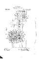
A construction embodying these improve- 1 ments is shown in the annexed drawings, in
-- of the driving gears in bearing 13. The
which,-Figure 1 is a longitudinal section of the lathe; Figs. 2, 3 and 4 are cross sections on the lines A-A, B-B, and C-C, respectively. Fig. 5 is a diagram of one the turret-head. The turret-head, which in the construction shown has six spindles 10, consists of two bearing-plates 11 connected to each other by a short cylinder 12, and is rotatable if a turret-head is rotated by means of a worm 1 1 actuated by a pulley 15. The intermittent locking of the turret-head is effected by means of a pin 16 slidable in the bearing 13, the said pin being adapted to engage recesses 17 in a ring 17 fixed to the turret-head; The means for actuating this pin will be described hereinafter.
The spindles are operated from a central driving shaft 18, on which are mounted two .wheels 19 and 20. On each spindle 10 there are two loose wheels 21 and 22 and a slidable clutch 23. The wheels 21 are connected by wheels 24: shown in dotted lines in Fig. 2, to the wheel 19, and the wheels 22 mesh directly with the wheel 20. Each of the clutches has a lever 25 pivoted to it on a pin 26, and the levers 25 project through apertures in the cylinder 12. The clutch levers 25 are attached to springs 27, which (Figs. 1, 2
This is necessary for Serial No. 465,134.
tend to hold them in engagement with the wheels 22. During the rotation of the turret-head each clutch-lever slides between a and 2 (Fig. 2) on an inclined guide-way 28, and is thus operated to engage the clutch with the respective wheel 21 so that the rotation of the spindle is reversed.
the operation of screweutting. The left-hand end (Fig. 2) of the inclined guide-way consists of a vertically movable slide 29, which is thrust upward by a spring 30. The downward movement of this slide is produced by aflever 31 pivoted at'32. This lever is actuated by means of an abutment 34: adjustable on a slidable bar 33, when the clutch-lever is to be released and the spindle is to be re coupled with a wheel 22. The bearing 13 is also provided with a slide-way 35 (Fig. 2), the purposeof which is to so move each clutch-lever at y that the respective clutch 23 is moved to its central position and the spindle uncoupled from both wheels 21 and 22. The finished work is removed from the spindles in this position, and replaced by blanks.
The tool-carrier or traversing head 36 is slidable on the bed in the known manner and is actuated by a spindle 37, which receives movement from the shaft 41 by means of a train of gear wheels 38 and alternative trains of gears 39, 39, and d0, 40*. The shaft 41 is provided with driving pulleys or other driving means. A shaft 43, on which are mounted the wheels 39 and 40, carries a clutch 14 adapted to be displaced by means of a lever pivoted at 15 onthe bed. A-lever 18 fixed to the pivot 45 is adapted to be actuated by means of adjustable abutmeuts 49 and 50 on the traversing head 36. An arm 51 of the lever 48 is rovided with n tches which can be engage by a spring-pressed pin 52. An arm 54: projecting from the lever 48 is weighted by means of a weight 53, or connected to a spring. The bar 33 is adjustably connected to an arm 55 of the tool-car rier. Near the pin 16 the bar 33 has a pivoted finger 56, which is normally held against an abutment 57 on the bar, by a spring 58.
At 59, on the bed, there is pivoted a bellcrank 60 connected to a clutch 62 slidable on the worm-shaft 61; to this bell-crank is pivoted the pin 16 (Fig. 3).
The action of the lathe is as follows: When the traversing head reaches its righthand end position, the abutment 4:9 places 1 I lever to the left; the
"- *L,.caus ed to enga *.threaded spind nected to the main shaft41 by means of the I wheels 38, 39 and 3,9.
the lever '48 in the position indicated by dotted lmes in Fig.1. The clutch 44 is then so placed? that .it clutches neither of the wheels 39,and 40, and the traversing head, {has no movement. ,Wheh the traversing head is to advanced. e., move toward the turret head, the lever 48 is moved by hand to the right, into the osition indicated by solid lines in Fig. 1, an the clutch 44 is thus e the gear wheel 39. The e or screw 37 .is thus con- When the traversing head has moved so far forward, that its on the lever 48,'the latter is 'movedrback into the position indicated by dotted lines,land.the welght 53 then rocks the clutch 44 is thus caused.
to engagethe wheel 40, and the direction of The -rotation of the spindle 37 is reversed. The
traversing head thereupon .makes its return movement. Before the advancin tools come v intocontact with the Work on t e spindles 10. a shoulder 63 of the bar 33, advancing 2'5 with the tool-carrienlis pushed under. the free'end of' the bell-crank 60 (Figs. '1 and 3), and thus locks the pin 16 in one of the. notches of the ring 17, so that the turret head cannot rotate While the tool is at Work.-
' At the end of the advance of the'traversing head-the abutment 34 acts on the lever '31 so that the clutch-lever-25 abuttin against the .upper endof the slide 29 is reheased and is actuated by its spring 27 to move the re- 35 spective clutch 23 into engagement with the.
wheel 22 so that the spindle 10 carrying the work which has beenthreaded has left hand rotation when the movement of the traversing head is reversed, in order that the cutter 40 can be vWithdrawn from" the thread cut \Vhen the traversing head reaches the posttion in which the tools no longer engage the v work, the finger' 56' depresses the free end of the bell crank 60 so that the in-16 is withdrawn from the'ring l7, and t e clutch .62 is caused to engage the Worm l4. The
' turret-head is thus released and caused to rotate. Just before the traversing head ,-reaches its right hand end osition, the er 56 releases the bell cran "60, and the spring 64 (Figs. 1 and 3), causes the pin 16 h to reengage the ring 17, the clutch 62' being at the same time disengaa 14, so that-,the turret-hea ceasesto rotate.
ment, normally element from the turret bar carried ed from the'worms What I claim and ters Patent is 1. In a turret lathe, the combination with a reciprocating tool head, of. an intermittently rotatable turret head, a lockin eleengaging said turret sad, so and htlding the-same against rotation and means carried by thetool head and reciprohable therewith to disen age said locking W ead, whereby the turret hea'd isfree to rotate. v 5 2.' Ina turret lathe, the combination witha reciprocating tool head and its driving mechanism, and a turret head,,of a slidable bythe tool head, means for automatically releasing 'the turret head, and "means for intermittently revolving the turret head, said means being thrown into action by the said slidablebar.
3; In a turret lathe, the combination with a [001 head, a sliding bar carried thereby, ofa turret head, having a recessed rim,'a pawl adapted to engage said recessed rim and lock the1 ti1nret head against movement, gearing ,for rotating t-he turret head, a'clutch, and
esire to secure by Let 55 levers, connected'to said pawl and'clutch, 30-
.said-slidingbiiiu' adapted to operate said leverswherebythfspavvl will be disenga ed fromtherecessed rim, and the clutch. coup ed to said gear so'thatthe turret head will be revolved. Q 1 V 35 .4. In a turret-lathe, the combination with a tool head and aregulating lever, gearin controlled by said lever, for moving the tool head, of adjustable abutments carried. by said tool head constructed andarranged to .9 throw the regulating-lever, into a' neutralpos'ition t6 uncouple the gears, and a weight secured to the regulating lever, to complete the throw of the 'lever, in onetdirection,
whereby the. gears will be coupled and. the
- direction .of movement of the tool head re-,
versed, and a locking element adapted to engage the lower end of the regulating lever, whereby it will be held against accidental displacement. u
The foregoing specification signed at Berlink, Germany, this twelfth day of N ovember,
I v MAR-TIN H- LANGKE. In presence of 3 I HENRY HASPER,
l mM HAUPT.
Priority Applications (1)
| Application Number | Priority Date | Filing Date | Title |
|---|---|---|---|
| US46513408A US962000A (en) | 1908-11-30 | 1908-11-30 | Semi-automatic turret-lathe. |
Applications Claiming Priority (1)
| Application Number | Priority Date | Filing Date | Title |
|---|---|---|---|
| US46513408A US962000A (en) | 1908-11-30 | 1908-11-30 | Semi-automatic turret-lathe. |
Publications (1)
| Publication Number | Publication Date |
|---|---|
| US962000A true US962000A (en) | 1910-06-21 |
Family
ID=3030398
Family Applications (1)
| Application Number | Title | Priority Date | Filing Date |
|---|---|---|---|
| US46513408A Expired - Lifetime US962000A (en) | 1908-11-30 | 1908-11-30 | Semi-automatic turret-lathe. |
Country Status (1)
| Country | Link |
|---|---|
| US (1) | US962000A (en) |
Cited By (1)
| Publication number | Priority date | Publication date | Assignee | Title |
|---|---|---|---|---|
| US3063131A (en) * | 1959-08-06 | 1962-11-13 | New Britain Machine Co | Indexing machine tool |
-
1908
- 1908-11-30 US US46513408A patent/US962000A/en not_active Expired - Lifetime
Cited By (1)
| Publication number | Priority date | Publication date | Assignee | Title |
|---|---|---|---|---|
| US3063131A (en) * | 1959-08-06 | 1962-11-13 | New Britain Machine Co | Indexing machine tool |
Similar Documents
| Publication | Publication Date | Title |
|---|---|---|
| US962000A (en) | Semi-automatic turret-lathe. | |
| US1389216A (en) | Metal-working machine | |
| US2327279A (en) | Screw machine | |
| US2339140A (en) | Automatic lathe | |
| US1484604A (en) | Automatic screw machine | |
| US809594A (en) | Self-acting multispindle-machine. | |
| US834359A (en) | Automatic lathe. | |
| US808887A (en) | Screw-making and metal-turning lathe. | |
| US971886A (en) | Turret-lathe. | |
| US1197541A (en) | Automatic turret-lathe. | |
| US1317766A (en) | thomas and f | |
| US530179A (en) | Screw-making machine | |
| US1363751A (en) | Automatic multiple-spindle lathe | |
| US857893A (en) | Screw-machine. | |
| US921721A (en) | Multiple-spindle machine. | |
| US530180A (en) | Screw-making machine | |
| US291455A (en) | Atjbin | |
| US2184475A (en) | Turret lathe | |
| US1294158A (en) | Turret-lathe. | |
| US842989A (en) | Spiral-cutting machine. | |
| GB119259A (en) | Improvements in and relating to Automatic Machine Tools. | |
| US1231255A (en) | Metal-working machine. | |
| US753158A (en) | Metal-turning machine | |
| US551119A (en) | Screw-slotting machine | |
| US1320272A (en) | potter |